

Page 1
Installing Your
Explora Family
System
Part Number 9300385 Rev A
November, 1995
About the
Explora Family
1
Explora
Product Line
2
Basic
Installation
3
Selecting
Screen
4
Resolution
Installing
Optional
5
Equipment
Pinout
Diagrams
6
Network Computing Devices
350 North Bernardo Ave.
Mountain View California 94043
Specifications
7
Troubleshooting
8
Page 2

Warnings and Certifications
This equipment has been tested and found to comply with the limits for a Class A digital device, pursuant to Part 15 of the FCC Rules. These limits are designed to provide
reasonable protection against harmful interference when the equipment is operated in
a commercial environment. This equipment generates, uses and can radiate radio frequency energy and, if not installed and used in accordance with the instruction manual,
may cause harmful interference to radio communications. Operation of this equipment
in a residential area is likely to cause harmful interference in which case the user will
be required to correct the interference at his own expense.
You are cautioned that any changes or modifications not expressly approved in this
manual could void your authority to operate this equipment.
This digital apparatus does not exceed the Class A limits for radio noise emissions from
digital apparatus set out in the Radio Interference Regulations of the Canadian Department of Communications.
Le présent appareil numérique n’émet pas de bruits radioélectriques dépassant les limites applicables aux appareils numériques de la classe A prescrites dans le Règlement
sur le brouillage radioélectrique édicté par le ministère des Communications du Canada.
Declaratio n of Con fo r m ity
Manufacturer’s Name: Network Computing Devices, Inc.
Manufacturer’s Address: 350 N. Bernardo Ave, Mountain View, CA 94043
Type of Equipment: X-Terminal
Model No.: Xplora and Xplorapro family of System Bases and Systems
Application of Council Directives: 89/336/EEC, 73/23/EEC
Standards to which Conformity is Declared: EN 55022, EN 50082-1, EN 60950
Importer’s Name: Network Computing Devices (UK) Limited
Importer’s Address: Unit 10, Grove Park 2, Waltham Road, White Waltham, Maiden-
head Berkshire, England SL6 3LW
We hereby declare the equipment specified above conforms to the above Directives and
Standards.
____________________________________________________
Andrew Hall, Director, Technical Services Northern Europe, NCD (UK) Ltd.,August
1995
Page 3
About the Explora Family
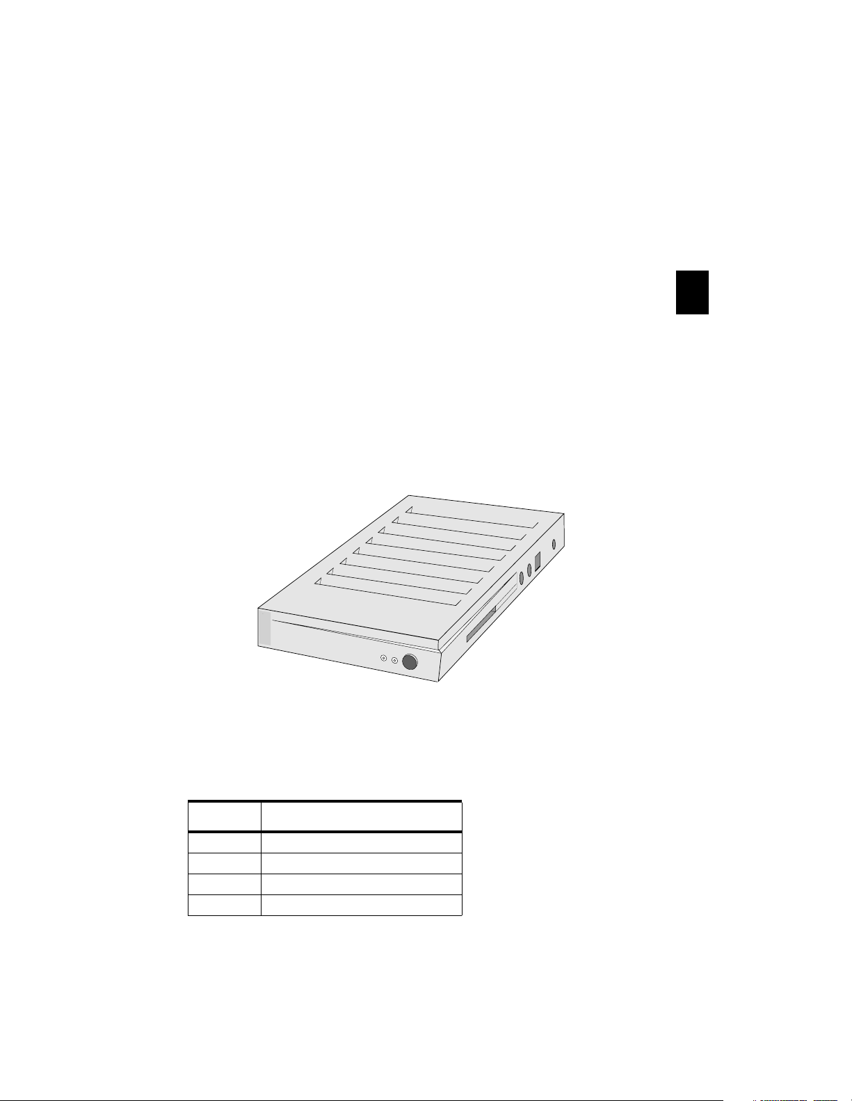
The Explora family consists of a base unit, several different monitors, a
mouse, and several keyboards. The base unit can be purchased alone
or with a monitor. The base supports many standard VGA or SVGA
third party monitors.
Explora Family Features
The Explora bases are advanced, small- signature X terminals that
include the following features:
• VGA/SVGA monitor support
• PS/2 mouse support
• Multiple keyboard choices
• Serial (RS-232 C) connection
• Parallel connection
• Externally accessible PCMCIA card slot
• Built-in twisted-pair and/or thin Ethernet connections (depending on
model)
1
X
x
x
N C D
N C D
The base is ergonomically designed with as small a footprint as
possible, making it ideal for environments where space is at a
premium. Table 1 lists the physical dimensions of the base.
Table 1: Explora Dimensions
Dimension
Height 1.625 inches (4.13 cm)
Width 7.25 inches (18.42 cm)
Depth 10.00 inches (25.40 cm)
Weight 1.51 pounds (0. 686 kg)
Explora
3
Page 4
Explora Product Line
N C D
N C D
X
xx
N C D
N C D
2
Explora
Power Supplies and
Accessories
PS/2 Mouse
*
3
2
1
R
O
L
O
C
Monitor
P
C
M
C
IA
PCMCIA Cards
(Optional)
Keyboard
Wall Mounting
Bracket with
Screws (Optional)
Security Device
with Screw
(Optional)
Memory SIMM
(Optional)
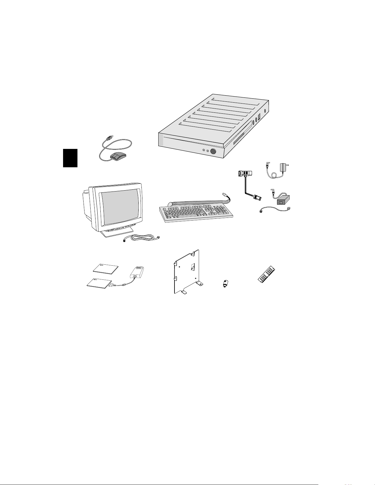
After unpacking the shipping cartons, make sure you have all of the
standard components and any optional components you may have
ordered. If any components are missing or appear damaged, contact
NCD at (415) 694-0650 or your representative immediately.
Note
Optional equipment installation is covered in Section 5.
* Optional Single Power Source Attachment, see Section 5.
4
Page 5
Basic Installation
N C D
N C D
Controls and Indicators
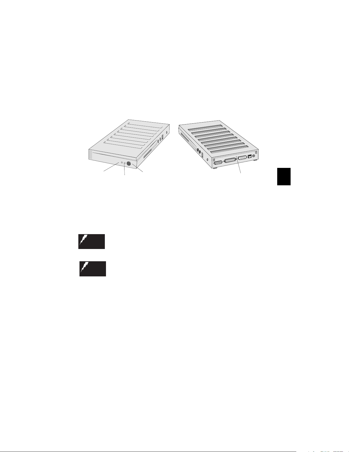
The controls and indicators are the same for all the models in the
Explora family.
Front View
X
xx
N C D
N C D
Network
Note
Activity
Indicator
If you are installing additional memory in your base, do not
Power
Indicator
complete the basic installation until you have installed the
memory. Go now to Section 5, Installing Optional Equipment.
Connections
Before connecting any cables, make sure the power is off.
WARNING
WA RNU NG
WARNING
WA RNU NG
Vor de m Anc h lie ßen von Kabeln sicherstellen, daß die Stromzufuhr unterbrochen ist
Do not connect any power cords to the Explora unless the monitor, keyboard, and
mouse ar e properly connected.
Kein Netzkabel in den Explora stecken, sofern Monitor, Tastatur und Maus nicht ordnungsgemäß angeschlossen sind.
Power
Switch
Back View
Twisted-Pair Link
Look Through Hole
3
.
Note
Explorapro has both twisted-pair and thin Ethernet connectors
for making network connections. Explora has only a twistedpair connector.
5
Page 6
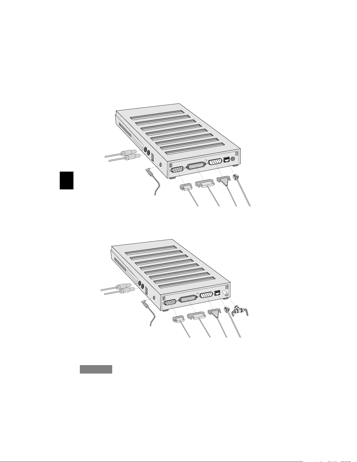
Look at the appropriate diagram for the model you have and make the
following connections: keyboard, mouse, monitor, network, and your
serial and/or parallel device. Connect the power supply last.
Explora
e
s
u
o
M
d
r
a
o
b
y
e
K
T
Serial
w
i
s
t
e
3
Power Supply
Monitor
Explorapro
Paral lel
d
-
p
a
i
r
Network
Connection
e
s
u
o
M
d
r
a
o
b
y
e
K
T
w
Thin
i
s
t
Ethernet
e
d
-
p
a
i
Serial
r
Network
Connection*
Power S upp ly
Monitor
Parallel
* Make only one network
connection at a time.
Caution
Do not set the monitor on top of the base. The base is not designed
to hold a monitor.
6
Page 7
Selecting Screen Resolution
When the terminal is first turned on, the display uses a default
resolution, depending on the installed video cable and monitor
capabilities. This setting may not provide the highest resolution and
refresh rate your monitor supports. See your monitor documentation
for supported resolutions.
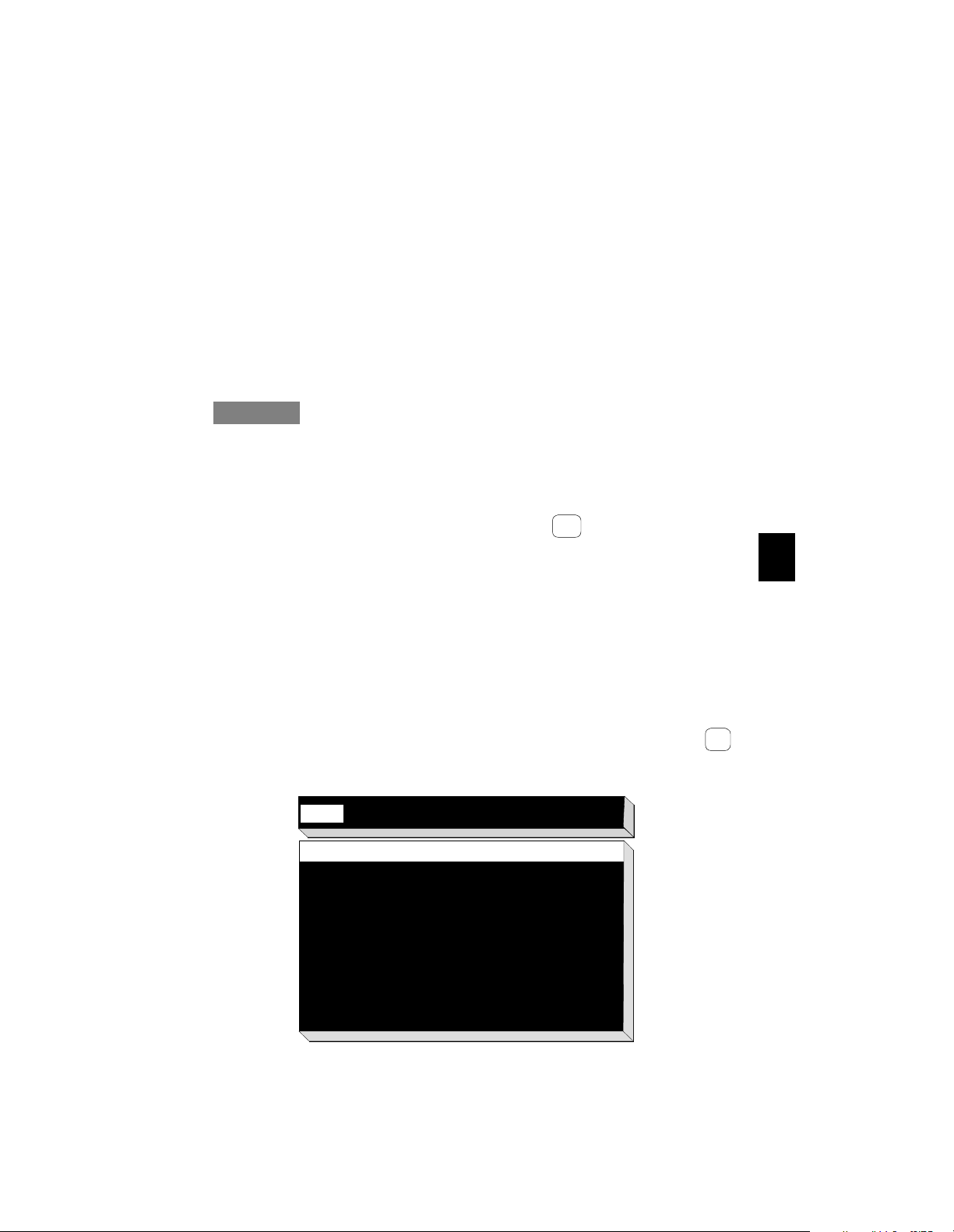
A menu is provided for selecting the correct resolution and changing
the DPI (dots per inch) setting for the monitor. You access this menu
through the Boot Monitor.
To change the resolution:
Caution
Selecting the wrong screen resolution can damage your monitor.
Make sure your selection is supported by your monitor.
1. Turn on the system or reboot (if the system is already on).
2. After the Boot Monitor title and version number, messages similar
to the following appear. Press the Escape key to interrupt the
booting process.
Searching for IP address...
Using IP address
Searching for subnet mask
Using subnet mask
...........................loaded
IP address of terminal
subnet mask
3. Depending on how the terminal’s booting parameters are set, you
may see more than one of these messages. Press Escape each time
one of them appears. This aborts the load process and puts the
system into the Boot Monitor (> prompt).
4. When you’re in the Boot Monitor (> prompt), press the Setup
key (or type se). The Main menu appears.
Esc
Setup
4
Help
Keyboard Monitor Network Boot Done
Help
Use the arrow keys to navigate through the menus
listed across the top of the screen:
Left, Right Go to previous or next menus.
Up, Down Go to previous or next field
Control-U Delete to beginninbg of line.
Escape Restore previous value.
Help for each field within a menu is shown along the
bottom of the screen.
Exit via the Done menu at the right of the screen.
within the current menu.
7
Page 8
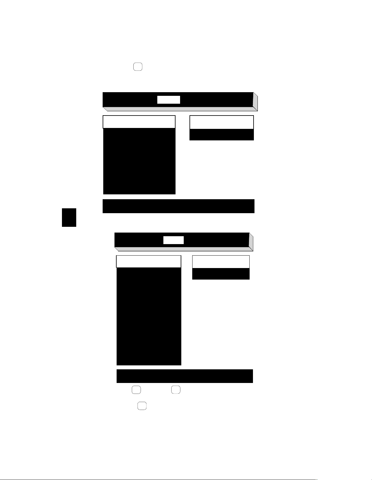
5. Use the right arrow key to select Monitor. The screen now dis-
→
plays the available monitor resolution settings
Help
Keyboard Monitor
Network Boot Done
Monitor Resolution
640 x 480 60Hz
Dots Per Inch
XX
640 x 480 72Hz
640 x 480 75Hz
800 x 600 60Hz
800 x 600 72Hz
800 x 600 75Hz
Suppor ted
resolutions for
Explora
1024 x 768 60Hz
1024 x 768 70Hz
1024 x 768 75Hz
Press Shift-T to rest new monitor parameters, Esc to stop test
4
Help
Keyboard Monitor
Monitor Resolution
640 x 480 60Hz
640 x 480 72Hz
640 x 480 75Hz
800 x 600 60Hz
800 x 600 72Hz
800 x 600 75Hz
1024 x 768 60Hz
1024 x 768 70Hz
1024 x 768 75Hz
1152 x 900 66Hz
1152 x 900 76Hz
1280 x 1024 70Hz
1280 x 1024 72Hz
1280 x 1024 75Hz
Network Boot Done
Dots Per Inch
XX
Supported
resolutions for
Explorapro
Press Shift-T to rest new monitor parameters, Esc to stop test
6. Press the up or down arrow keys to select the correct
↓
↓
setting for your monitor.
7. Press the right arrow key to select Dots Per Inch.
→
8
Page 9
8. Enter the numerical value that matches the resolution you have
Shift
Τ
selected. (Or leave the default value.)
9. To test the selected refresh rate, press Shift -T .
Running this test generates a cross hatch test screen pattern. If the
refresh rate you select is not supported by the monitor, the test
pattern does not appear.
10. Press any key to return to the Monitor menu.
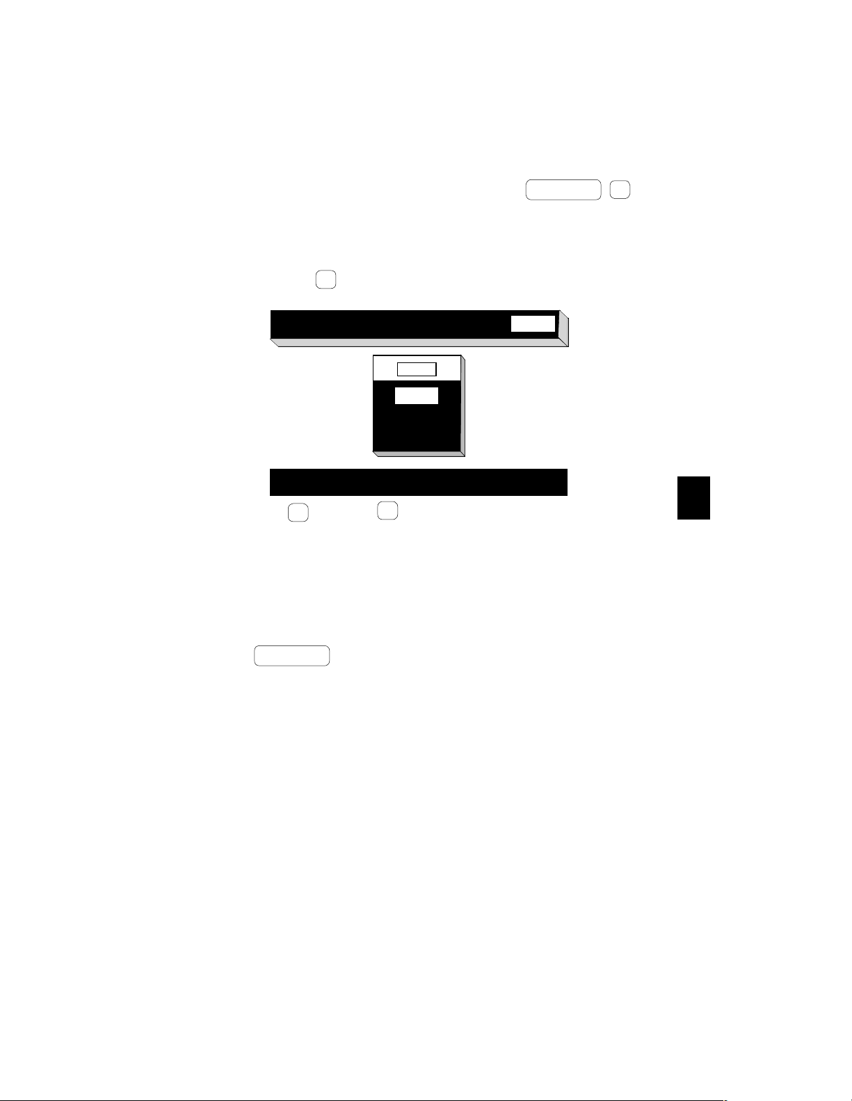
11. Press the right arrow key to select Done. The following menu
→
appears.
Help
Keyboard Monitor Network Boot Done
Done
Reboot
Exit
Undo
Save Parameters and reboot. Press <Return> to confirm
12. Use the up or down arrow keys to select one of the options
↓
↓
from the Done menu.
Reboot
Exit
-- saves the settings you changed and reboots the system.
-- saves the settings and returns you to the Boot Monitor.
Undo -- reloads the parameters that were in effect when you
entered the menus. The system continues to display the menus.
4
13. Press .
Return
If you save your selection, you do not need to repeat this procedure
unless you change to a different type or size of monitor.
9
Page 10
Installing Optional Equipment
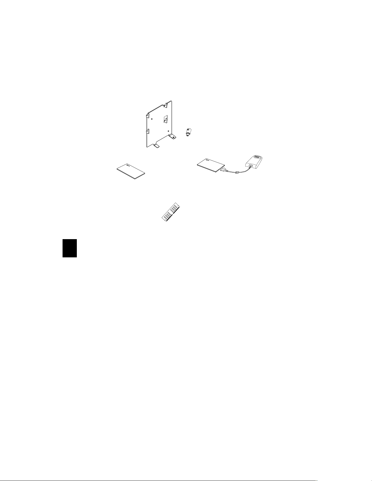
The following optional equipment is available for your Explora.
Security Device
Wall Mount
Bracket
P
C
M
C
IA
PCMCIA card
Memory SIMM
Audio PCMCIA
Card with Audio
Interface Module
Note
5
If you are adding additional memory, do so before doing the
basic installation in the previous section.
Installing Additional Memory
You can add additional memory to your unit at any time. It can be
purchased from NCD or other vendors. Contact NCD Technical
Support for information about approved vendors. Only SIMMs
supplied by NCD are covered under NCD’s warranty.
Notes
Table 2 lists the SIMM specifications.
Explora has 4 MB of built-in memory and 1 MB of built-in
display memory.
Explorapro has 8 MB of built-in memory and 2 MB of built-in
display memory.
You can add one additional SIMM to Explora, and two
additional SIMMs to Explorapro.
10
Page 11
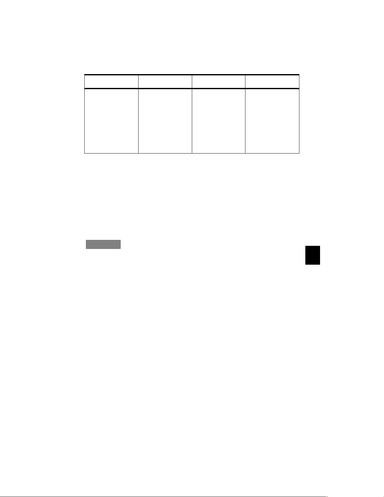
Table 2: SIMM Specifications
Speed Profile Thickness Size
Fast -page mode. 60
nanoseconds (ns) or
fast er. (Low er ns ratings are faster.)
72-pin.
Notes
When installing additional memory in Explorapro, observe the
Low prof ile (maximum 1.1 inches tall).
Tin-plated SIMM contacts should be used.
Board thickness of
0.047 to 0.054 (0.050
inch nominal). Installing SIMMs that are
out of specifications
may damage the
SIMM socket or cause
the terminal to beh ave
erratically.
32-bits wide.
1M (256Kx32 SIMM)
2M (512Kx32 SIMM)
4M (1Mx32 SIMM)
8M (2Mx32 SIMM)
16M (4Mx32 SIMM)
32M (8Mx32 SIMM)
following rules:
If you are adding only one SIMM, use socket J9.
If you are adding two different size SIMMs, use socket J9 for
the larger SIMM.
Adding more memory does not improve terminal operation,
but may be required by your applications.
Caution
Installing additional memory is a four step procedure: 1) disassembling the terminal base, 2) installing the SIMM(s), 3) reassembling
the terminal base, and 4) testing the memory after your terminal is
up and running. If you don’t feel confident performing these procedures on your terminal, refer the unit to a qualified service
center.
5
11
Page 12
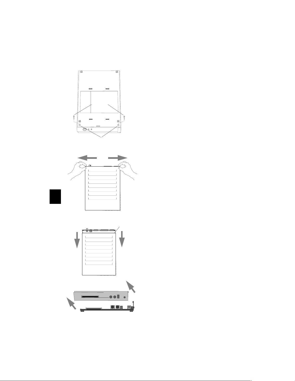
Disassembling the Base
Bottom of Base
Remove
Screws
1. Remove all cables connected to the base.
2. Turn the base upside down, and
place it on a flat surface, so that
the base bottom is facing up and
the front is facing you.
3. Locate the two phillips screws in the holes on the base bottom front corners.
4. Remove the two screws.
Screw
holes
5. Turn the base over and place it on
a flat surface, so that the base top
is facing up and the front is facing
you.
6. Grasp the tabs protruding from the back of the unit with your forefinger as shown.
5
7. Gently pull the tabs away from the center and at the same time:
1/2 Inch
Gap
• apply pressure with your thumbs
to the base top and
• using your thumbs, pull the top
cover towards the front. (Towards
you.)
8. When the cover is about one-half
(
) inch from the back of the
1/2
bottom housing, pull up on the
top cover and remove it.
12
Page 13
Installing SIMMs
If your base already has a SIMM or SIMMs installed, proceed to the
next heading “Removing SIMMs” and then return to this section for
installation instructions. If not, follow these steps.
Caution
SIMMs and other components located on the logic board can be
damaged by Electrostatic Discharge (ESD). Make sure you touch a
suitable ground before handling any SIMM. If possible, set the
base on an anti-static mat and wear a grounding strap.
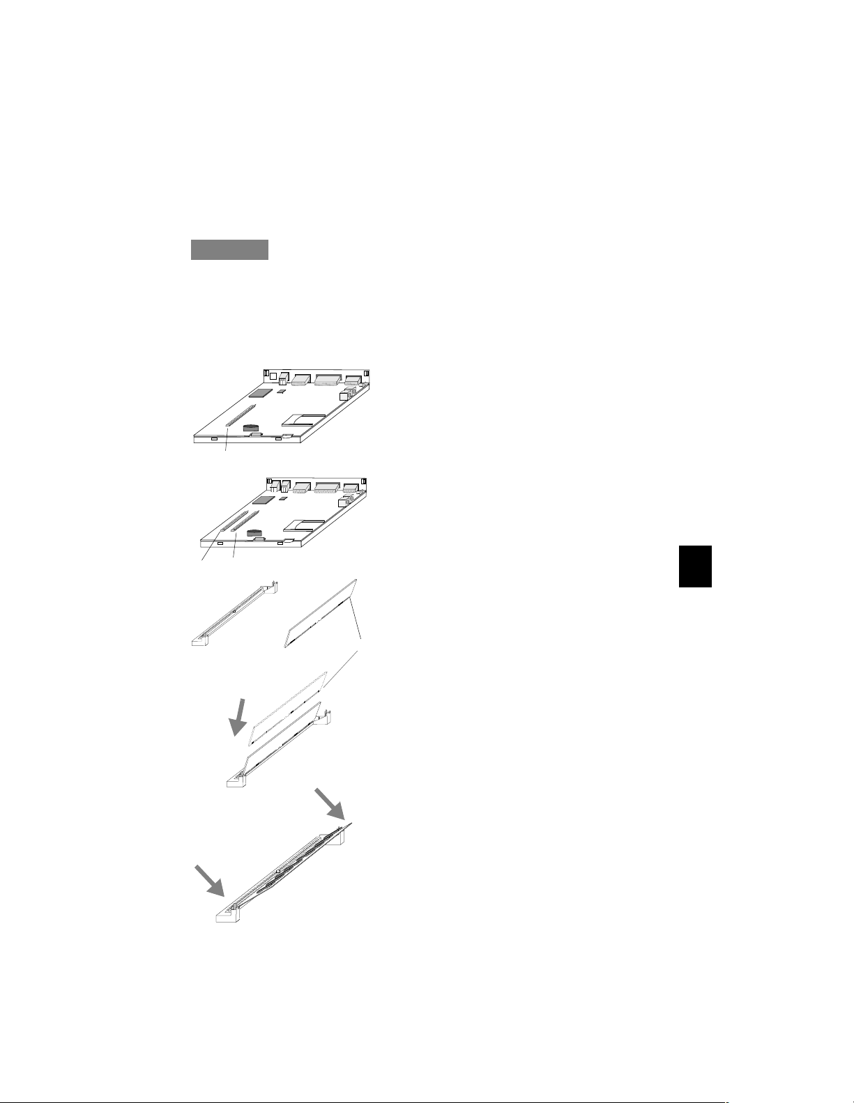
J10
J9
J9
S
c
k
o
Explora
e
t
Explorapro
S
M
I
M
The SIMM socket(s) are located on the
left side of the logic board.
To install the SIMM(s):
1. Orient the SIMM so that the notch is facing towards the back of the logic board.
Notch
2. Insert the SIMM into the socket at about a 45 degree angle.
5
3. When you are certain the SIMM is
inserted all the way, press down
on both ends of the SIMM until it
clicks into place. The SIMM
should go past the metal tabs on
each end of the socket.
The SIMM should lie at about a 25
to 30 degree angle in the socket.
13
Page 14
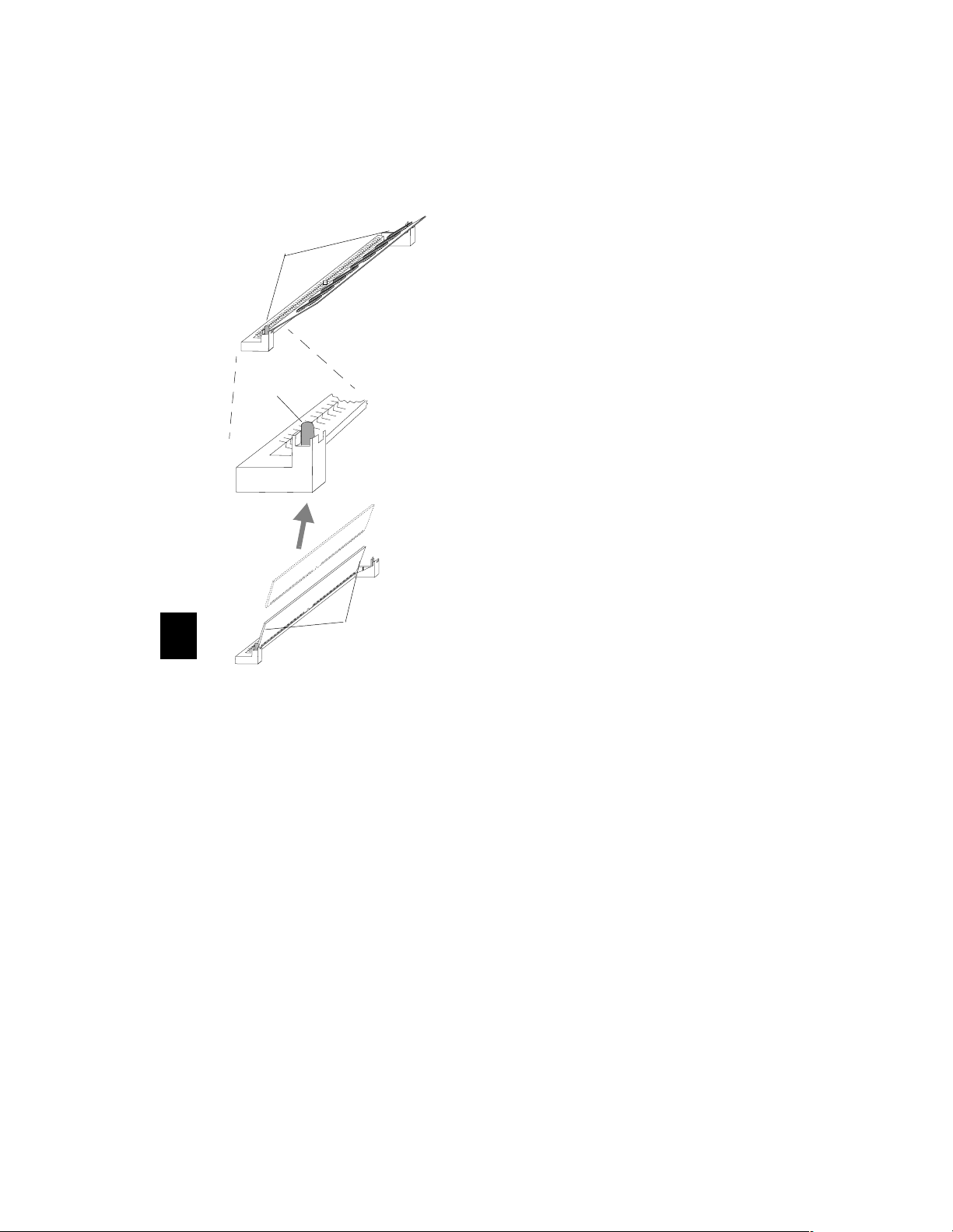
Removing SIMM
T
s
a
b
l
M
e
a
t
To Rem ove a SIMM
1. Using your two forefingers or
your thumbs, pull back on the
two metal tabs located on each
end of the SIMM socket.
Metal
Ta b
2. As you pull back on the tabs, the SIMM pops up past the metal tabs.
3. Hold the SIMM on both ends
(you should always handle
SIMMs by the edges only), and
remove it from the socket.
H
o
l
d
I
S
M
M
s
n
5
e
d
E
g
o
s
14
Page 15
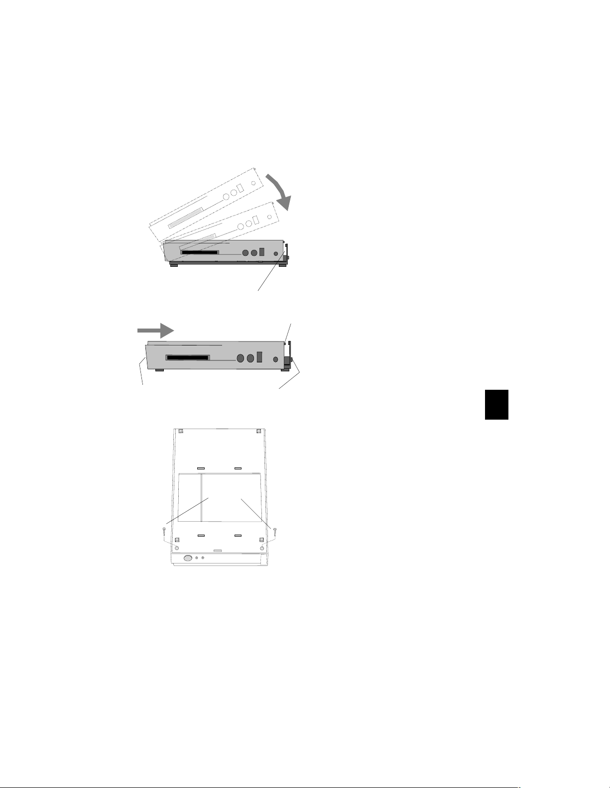
Reassembling the Base
To reassemble the base, follow these steps:
1. Swing the front of the top
cover over the front edge of
the bottom section and continue down with the rest of
the top cover unit it covers the
bottom section (this is a tight
fit). There should be a one-half
(1/2) inch gap between the
bottom section back, and the
top cover back.
Push
Here
Side View
Bottom of Base
Insert
Screws
1/2 Inch
Gap
Hold
Here
Note
Make sure the top cover is
resting completely flat on
Tab s
the bottom section before
doing step 2.
2. Hold the back of the bottom
section and push the top cover
toward the back until the two
tabs click through the two
openings on the bottom
section.
3. Once the top cover and
bottom section are together as
a unit (base), turn it upside
down, so that the base bottom
is facing up and the front is
facing you.
4. Secure the base together by
screwing in the two phillips
screws into the two holes
located at the front corners on
the bottom.
5. Tighten the screws so they are snug, but do not over tighten.
6. Turn the base upright and refer to Section 3, to install the cabling.
7. After the system is installed,
perform the memory test, presented next.
5
15
Page 16
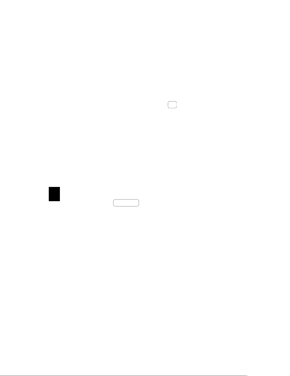
Testing Memory
Before running the memory test, go to Section 3, “Basic Installation”
and install the rest of the system.
To run the memory test, you need to access the Boot Monitor.
Accessing the Boot Monitor
1. Turn on the system or reboot (if the system is already on).
2. After the Boot Monitor title and version number, messages similar
to the following appear. Press the Escape key to interrupt the
Esc
booting process.
Searching for IP address...
Using IP address
Searching for subnet mask
Using subnet mask
...........................loaded
IP address of terminal
subnet mask
3. Depending on how the terminal’s booting parameters are set, you
may see more than one of these messages. Press Escape each time
one of them appears. This aborts the load process and puts the
system into the Boot Monitor (> prompt).
Memory Test
Run the memory test as follows:
1. At the Boot Monitor prompt (>), type ex and press Return.
5
2. Type the number associated with the Test Available Memory test and press Return .
Enter test type? # (for Test Available Memory test)
<CR>
3. Press Return to run the test once.
F Loop forever
E Loop until error
Q Main menu
<cr> Test once
Esc Abort testing
Enter choice? <CR>
The diagnostic code displays either
Pass -00000001
to signify that the memory is good, or a message similar to the following if an error was detected:
Expected bad component is JXX.(Indicates socket number
of bad SIMM.)
If there are no errors, go to Step 6.
If errors are reported, continue with Step 4.
Return
16
Page 17
4. Remove the bad SIMM from the socket indicated and rerun the
memory test to confirm that the remaining memory is good.
5. Add a new SIMM, and rerun the memory test to confirm that the newly installed SIMM is good.
6. Exit from the test and return to the Boot Monitor by typing:
Enter test type? Q <CR>
7. Reset the terminal by typing:
> rs <CR>
For information about the Boot Monitor commands, refer to
software documentation
.
NCDware
17
5
Page 18
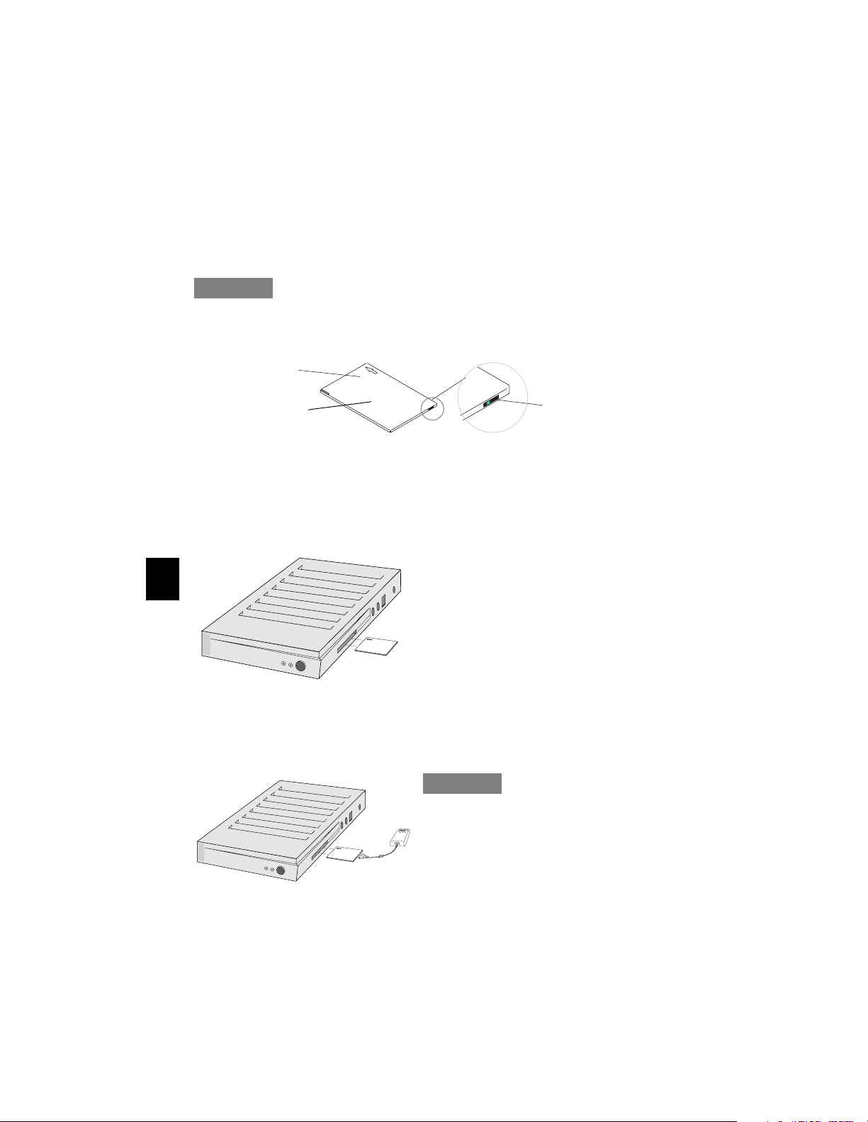
Installing PCMCIA Cards
N C D
N C D
N C D
N C D
The PCMCIA cards are 68-pin credit-card size devices that fit into the
base PCMCIA slot. These cards can be ordered directly from NCD or
from other vendors. Most PCMCIA cards have an arrow on the top
face side showing the direction of insertion into the PCMCIA slot. The
cards are keyed and cannot be installed upside down.
Caution
Do not insert or remove the PCMCIA card while the unit is running; always turn off the terminal first.
Directional
Arrow
a
d
r
o
p
C
o
f
T
The rear edge of the PCMCIA card may have a write protect/enable
switch. If your card has this switch, it should be in the OFF position. If
write protect is enabled, data cannot be written to the card and an
error message appears if you try to do so.
To install a PCMCIA card:
5
1. Shut off the terminal.
2. If your PCMCIA card has a
write protect switch, set it to
X
x
x
N C D
N C D
P
C
M
C
IA
PCMCIA
Card
OFF.
3. With the arrow side facing up,
slide the card into the PCMCIA
slot until you feel the card make
contact with the pins in the
socket.
4. Firmly push the card into the socket to seat it.
Write Protect/Enable
Switch set to OFF (If
Applicable)
Caution
Do not force the card into the
socket; the card should go
Xxx
N C D
N C D
P
C
M
C
IA
Audio PCMCIA
Card with Audio
Interface Module
straight in.
5. If the PCMCIA is an audio card, attach the Audio Interface Module to the connector on the card.
18
Page 19
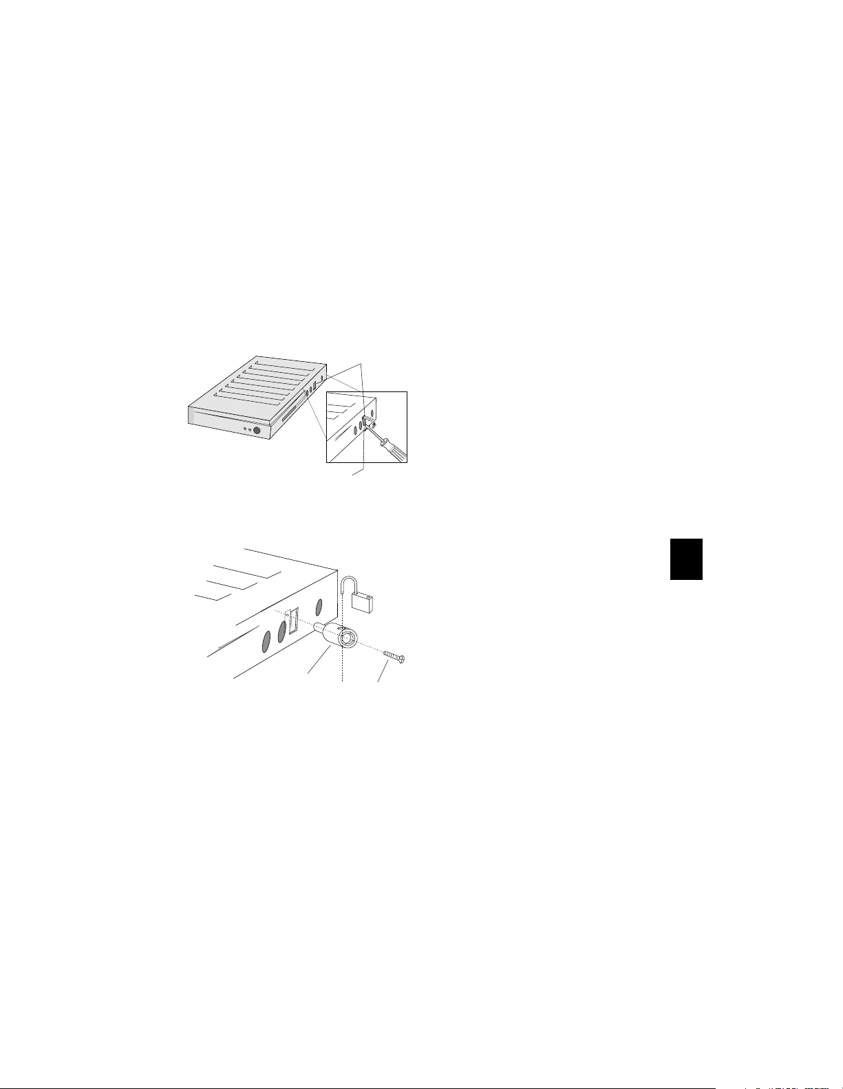
Installing the Security Device
N C D
N C D
Both models have a rectangular security cover located next to the
keyboard connector. This is where the security device is located once
the cover is removed. The security device can be used with or without
the mounting bracket.
If you are using the optional mounting bracket and are going to use
the security device with it, do step one of this procedure and then go to
the next part in this section “Installing the Mounting Bracket.” Yo u do
not have to return to this section.
Security
Cover
1. To remove the security cover,
insert a medium sized flat
blade screwdriver into the
Xxx
N C D
N C D
bottom of the slot.
2. Gently pry out the security cover.
3. Insert the security device into
Pry
Here
the slot so that the center of
the device lines up with the
screw hole in the chassis.
4. Insert an M2.5 machine screw
(supplied) through the center
Lock
of the security device and into
the hole.
5
5. Tighten down the machine bolt.
6. To secure the unit, insert a lock or cable through the outer hole in the security device.
Security
Device
M2.5
Pan-Head
Screw
19
Page 20
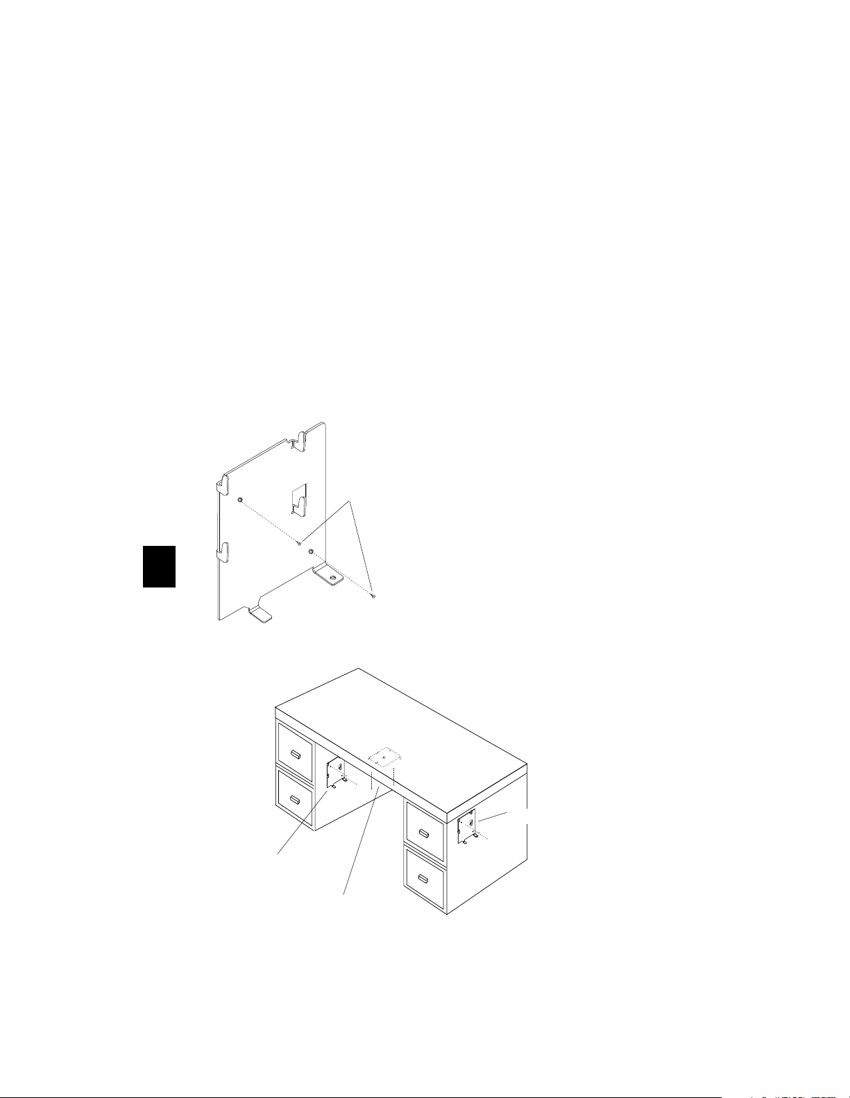
Installing the Mounting Bracket
There are various places the mounting bracket may be attached.
Examples include attaching the bracket on a wall or on your desk, as
shown in the illustration. In determining where to attach the bracket,
keep the following in mind:
• Are the cables you have attached to the base long enough to reach
from the bracket to the keyboard, mouse, and monitor?
• Is the fixture where you’re attaching the bracket secure enough to hold
the bracket and base?
• Is the area where you’re placing this bracket and base out of the way
of traffic, so that the unit will not be bumped?
• Is there enough clearance around the unit for cables and air
circulation?
To mount the bracket:
1. Select the location to attach the bracket.
2. Use the two flathead
Use two screws
5
screws (supplied), and
secure the bracket to the
fixture.
Make sure the screw
heads are flush with the
bracket before attaching
the base.
Inside of Desk
Possible areas for mounting the bracket.
Outside of Desk
Underneath Desk Top
20
Page 21
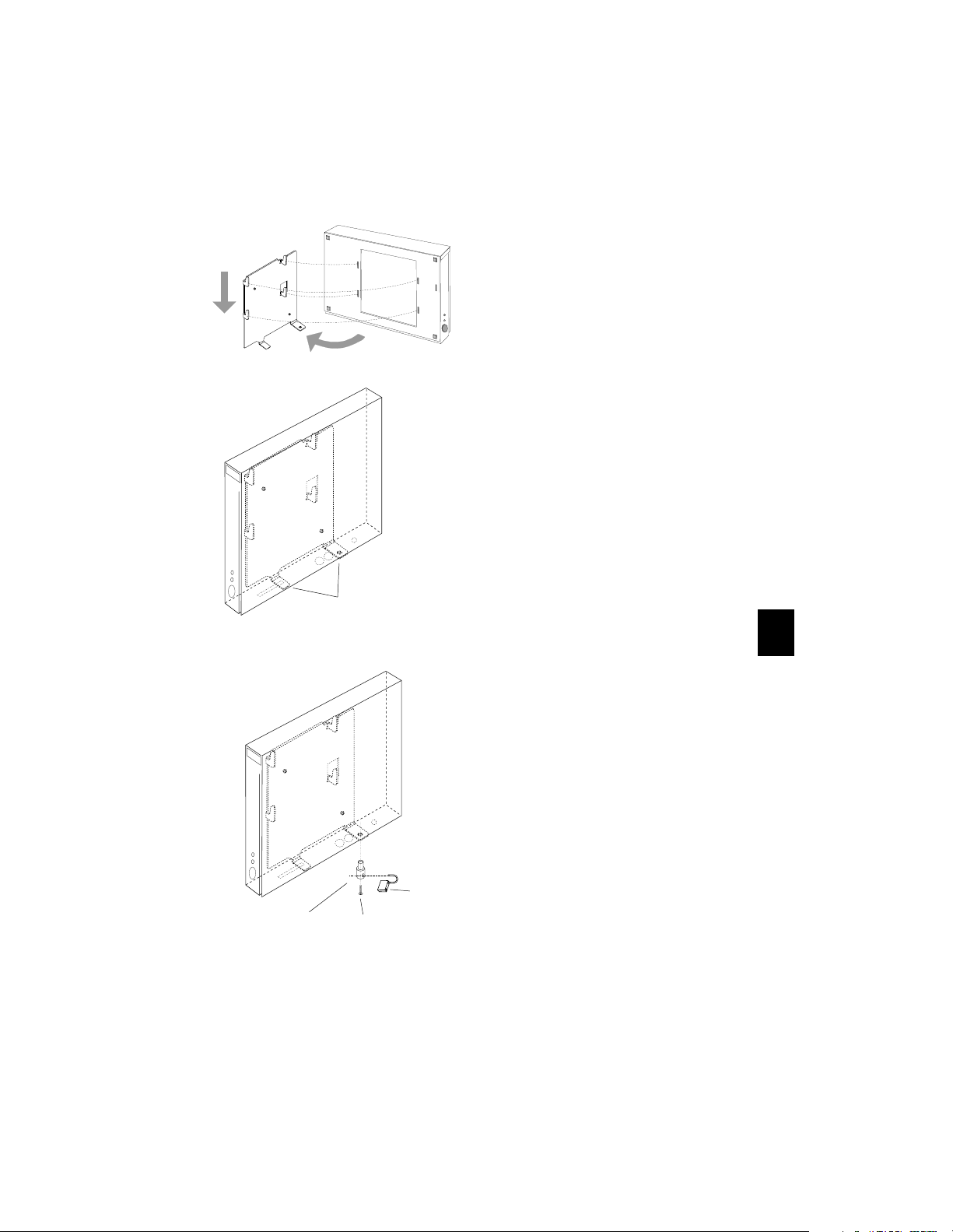
Securing the Base to the Mounting Bracket
To attach Explora to the bracket:
1. Align the tabs on the bracket with the slots on the bottom of the unit.
2. Insert the tabs into the slots and at the same time, gently push down on the unit.
Align tabs and slots
Side of unit resting
on angle tabs
Security device and
screw
M2.5
Pan-Head
Screw
Lock
The side of the base should rest
on the two angle tabs protruding from the bracket, shown in
the diagram.
Using the Security Device
To use the security device with the
mounting bracket, do the following:
1. Before attaching the base to the
bracket, make sure you remove
the security cover from the side
of the terminal. If you have not
done this, go back to step one in
“Installing the Security Device”
and remove the security cover.
2. Attach the base to the mounting bracket, using the steps above. Then return here to step 3.
3. Push the small part of the security device through the hole in
the angle tab on bracket and
through the security cover slot,
so that the center hole of the
device aligns with the threads
on the inside of the chassis.
4. Insert the pan-head screw
(M2.5, supplied) through the
center of the security device,
and screw it all the way in, until
it is secure.
5. To lock the unit to the bracket,
insert a lock or security cable
through the hole in the large
area of the security device.
5
21
Page 22
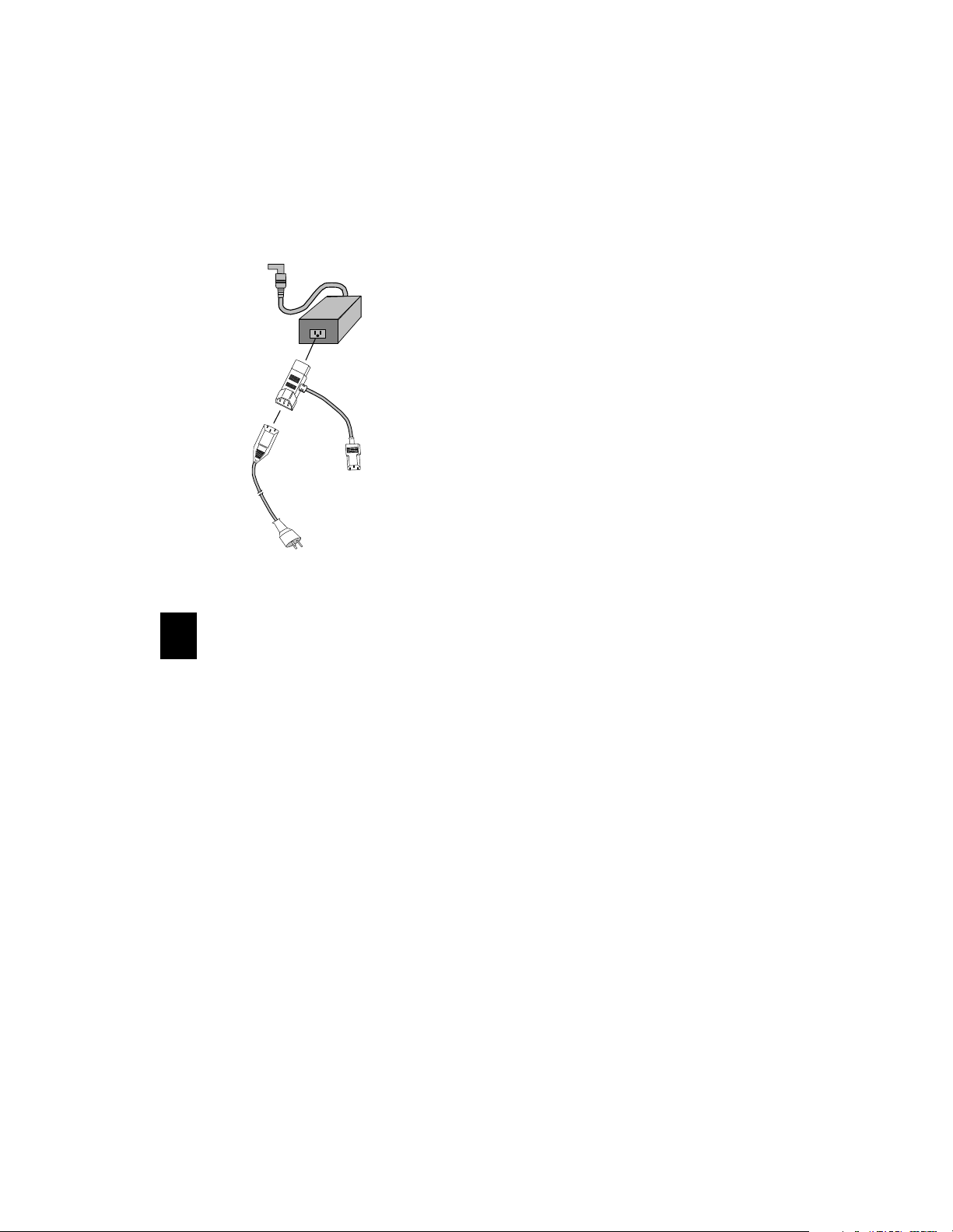
Single Power Source Attachment
To install the Single Power Source Attachment, follow these steps:
To
Base
1. Insert one end of the Single Power Source Attachment into the power supply block.
2. Insert the power cable into the
Single Power Source Attachment connector.
3. Insert the Single Power Source
Single Power Source
Attachment
Attachment extension connector into the monitor.
4. Attach the power supply connector to the base unit.
To M on i t or
5. Connect the power cable to the power source.
To AC
Power
Source
5
22
Page 23
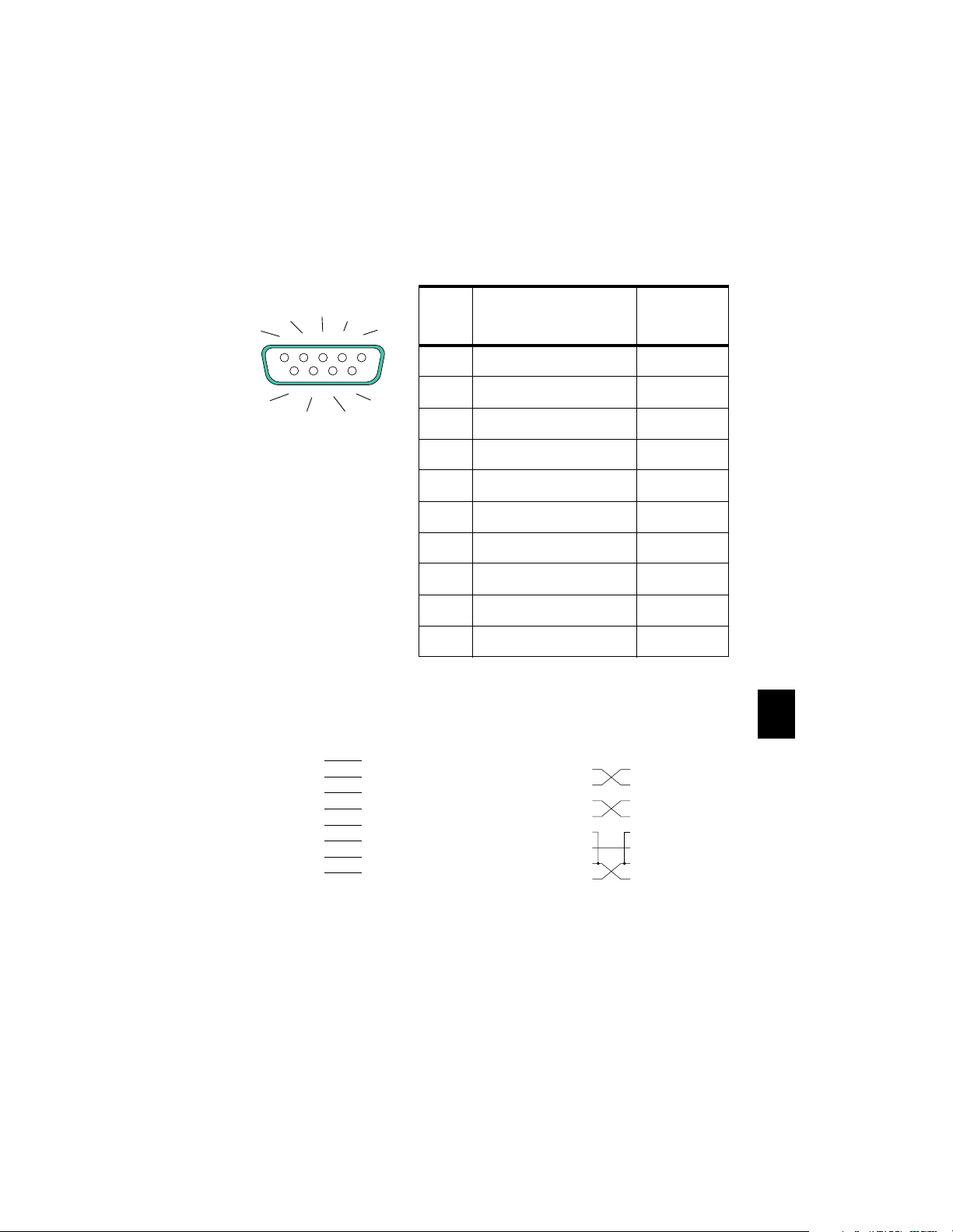
Pinout Diagrams
This section contains pinout diagrams for the base connectors.
Serial Connector (RS 232 C Serial Connector
TD
DCD
DSR
RD
1
2
6
RTS CTS
DTR
SG
4
5
3
Pin Signal
1 Data Carrier Detect In
98
7
2 Receive Data In
N/C
3 Transmit Data Out
4 Data Terminal Ready Out
5 Signal Ground --
6 Data Set Ready In
7 Request To Send Out
8 Clear To Send In
9 Not Connected
Shell Protective GND
)
Signal
Direction
Modem
DCE 25-Pin
Transmit Data 2
Receive Data 3
Request to Send 4
Clear to Send 5
Data Set Ready 6
Signal Ground 7
Data Carrier Detect 8
Data Terminal Ready 20
Terminal
DTE 9-Pin
3 Transmit Data
2 Receive Data
7 Request to Send
8 Clear to Send
6 Data Set Ready
5 Signal Ground
1 Data Carrier Detect
4 Data Terminal Ready
DTE 25-Pin
Transmit Data 2
Receive Data 3
Request to Send 4
Clear to Send 5
Data Set Ready 6
Signal Ground 7
Data Carrier Detect 8
Data Terminal Ready 20
23
Host
Terminal
DTE 9-Pin
3 Transmit Data
2 Receive Data
7 Request to Send
8 Clear to Send
6 Data Set Ready
5 Signal Ground
1 Data Carrier Detect
4 Data Terminal Ready
6
Page 24
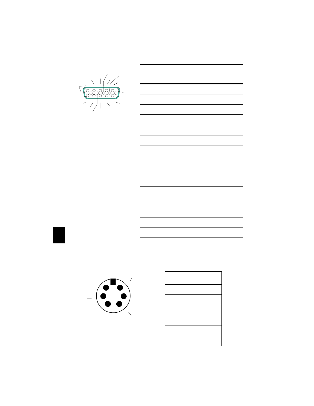
Monitor Connector
G
MD-3
MD-2
10
15 14 13
VS
BVG
BV
4
3
5
HS
N/C
GVG
GV
RV
2
1
RVG
6
11
12
MD-0
MD-1
Pin Signal
1 Red Video Out
2 Green Video Out
3 Blue Video Out
Signal
Direction
4 Monitor Detect 2 In
5 Ground --
6 Red Video Ground --
7 Green Video Ground --
8 Blue Video Ground --
9 No Connection --
10 Ground --
11 Monitor Detect 0 In
12 Monitor Detect 1 In
13 Horizontal Sync Out
6
Keyboard and Mouse Connectors
Clock
56
+5V dc
4
3
12
Data
14 Vertical Sync Out
15 Monitor Detect 3 In
Shell Chassis Ground --
Pin Signal
1 Data
Ground
2 Reserved
3 Ground
4+5V dc
5Clock
6 Reserved
24
Page 25
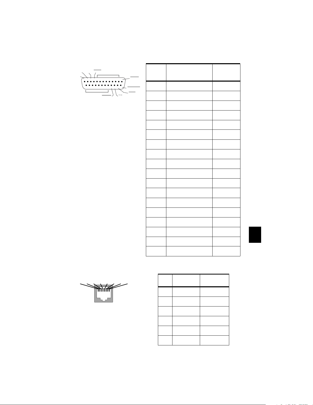
Parallel Connector
ACKNLG
BUSY
PE
SELECT
13 12 11 10 9 8 7 6 5 4 3 2 1
25 24 23 22 21 20 19 18 17 16 15 14
GND
Data lines 0-7
SELECTIN
INIT
STROBE
AUOTFEEDXT
ERROR
Pin Signal
Signal
Direction
1STROBE In
2 Data 0 In
3 Data 1 In
4 Data 2 In
5 Data 3 In
6 Data 4 In
7 Data 5 In
8 Data 6 In
9 Data 7 In
10 ACKNLG Out
11 BUSY Out
12 PE Out
13 SELECT Out
14 AUTOFEEDXT In
15 ERROR Out
16 INIT In
17 SELECTIN In
18 - 25 GND N/A
RJ-45 Connector (Twisted-pair Ethernet)
TD+
RD+
TD-
345612 78
RD-
Pin Name Function
1 TPOP Transmit+
2 TPON Transmit-
3 TPIP Receive+
4/5 Not Used --
6 TPIN Receive-
7/8 Not Used --
25
6
Page 26
Specifications
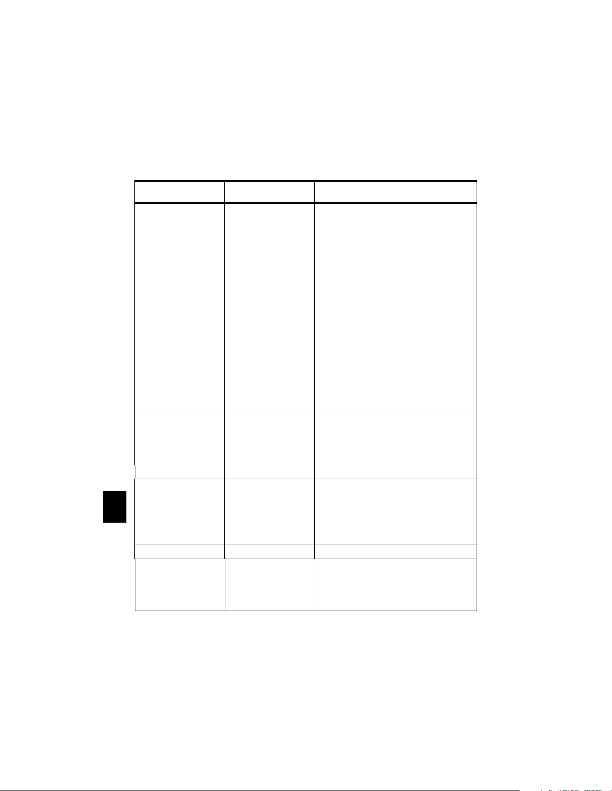
The following table contains Explora family specifications.
Table 3: Explora Family Specifications
Category Topic Specification
Hardware architecture Microprocessor
Explora PPC 403GB
Explorapro PPC 403GA
Coprocessor S3 968 (both models)
DRAM
Explora 4 MB
Explorapro 8 MB
PROM 256KB (both models)
Memory upgrades 32-bit, 60ns, fast-page mode SIMMs
Explora 1 SIMM slot expandibility
Explorapro 2 SIMM slots expandibility
NVRAM 512 Bytes (both models)
Display memory
Explora 1 MB
Explorapro 2 MB
Display monitor Resolution
Explora 640x480, 800x600, 1024x768
Explorapro 640x480, 800x600, 1024x768, 1152x900,
1280x1024
Refresh rate Up to 76 Hz
Power
Transformer
7
Power Consumption 19 Watts (maximum)
Environmental
operating range
AC voltage and
AC frequency
North America 90-132 VAC, 60 Hz (+/- 3 Hz)
European/Australian 180-265 VAC, 50 Hz (+/- 3 Hz)
Japanese 85-110 VAC, 47 - 63 Hz
Temperature 10× C (50× F) to 40× C (104× F)
Humidity 10% to 90% non-condensing
Altitude Up to 3,050 meters (10,000 feet)
26
Page 27
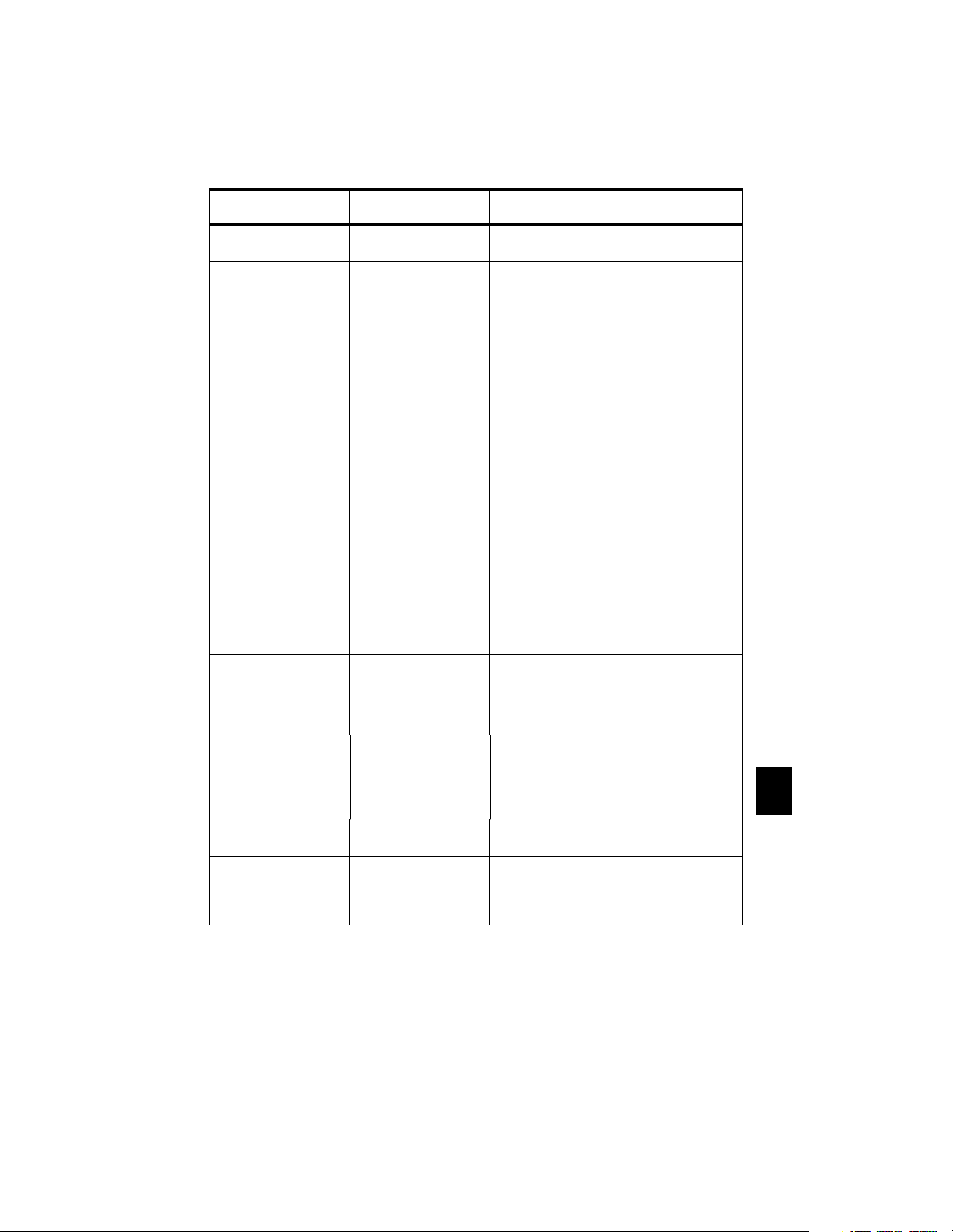
Table 3: Explora Family Specifi cations (Continued)
Category Topic Specification
Controls and indicators Base unit Power switch, Power LED, Network Activity,
and Twisted-Pair Link Indicator.
Keyboard N-97/Kana: Three configurable LEDs
(Unlabeled, Caps Lock, and Network
Activity).
N-101/N-102: Three configurable LEDs
(Num Lock, Caps Lock and Scroll Lock)
N-108LK: Four configurable LEDs (Hold
Screen, Lock, Compose, and Network
Activity)
N-123 Sun Type 5 compatible: Four
configurable LEDs (Caps Lock, Compose,
Scroll Lock, and Number Lock)
3270 Lexmark: Three configurable LEDs
(Network Activity, Caps Lock, and Number
Lock)
Input Devices Keyboards 97-key UNIX style keyboard (N-97),
101-key PS /2 style keyboard (N101PS),
102-key international version (N-102),
108-key LK401-compatible keyboard (N108LK),
97-key Kana keyboard (Japanese characters) (N-97KAN)
N-123 Sun Type 5 compatible keyboard (N-
123), 3270 Lexmark
Mouse Three-button, PS/2
Communications Thin (BNC) Built-in 10Base2 Thin Ethernet transceiver
Twisted-Pair Built-in 10BaseT Twisted-pair Ethernet trans-
ceiver
Serial port RS-232 C up to 115.2 K baud
Parallel port Connector: 25-pin
PCMCIA Standard PCMCIA PC card Standard
Physical Dimensions Height
Width
Depth
Weig ht
Data: 8-bit parallel
Synchronization: STROBE pulse
Handshaking: ACKNLG or BUSY signal
Logic level: TTL level
Release 2.01, 68-pin connector
1.625 inches (4.13 cm)
7.25 inches (18.42 cm)
10.00 inches (25.40 cm)
1.51 pounds (0.686 kg)
7
27
Page 28

Troubleshooting
Problems Caused by Faulty Hardware
NCD terminals have four major components: base, monitor, keyboard,
and mouse. If found to be faulty, the base and/or monitor must be
returned for repair. The mouse and/or keyboard are replaceable.
Isolating Faulty Components
One of the best ways of tracking down hardware problems is to swap
components among compatible terminals. Swapping components lets
you determine which component is faulty.
For example, if a keyboard appears to be faulty, turn off the terminal,
disconnect the keyboard, and connect a keyboard from another NCD
terminal. If the second keyboard works, you know that the problem is
with the first keyboard and not with another component, such as the
keyboard controller in the base.
Mouse Troubleshooting
Most mouse problems are caused by a dirty mouseball or a loose
connection between the mouse cable and the base. If you have
problems using your mouse:
1. Check the mouse cable connector. Make sure it is firmly connected
to the base’s mouse connector.
2. Turn the mouse upside down and remove the ball. Clean the ball
and its socket, and reassemble the mouse.
3. Clean your mouse pad or the area of the desk where your mouse
sits.
Monitor Troubleshooting
Generally, if the monitor is out of focus, too bright, or too dark, adjust
the monitor’s brightness and contrast knobs. Each monitor model has
its own set of controls. Check the monitor operating booklet for more
information about your monitor.
Base Troubleshooting
A flashing power indicator indicates there is a hardware problem in
the base.
8
If you find you must return a base for repair, send it in the same
configuration as when it failed.
In Case of Trouble
If you encounter difficulties, you can send e-mail or a FAX to NCD
Technical Support or contact them by phone.
For information on services available from NCD Technical Support,
contact your NCD representative or send mail to [email protected].
28
Page 29

Phoning Technical Support
You can phone (415) 691-7445 and ask for Technical Support. Be
prepared to provide at least the following information when you call:
• Model name of the terminal
• Full description of the problem
• Whether you have tried swapping components to isolate the problem
• How long has the terminal been working
• Whether the problem is constant or intermittent
• Amount of memory installed in the terminal
• Part number and serial number
• Release of NCDware you are running
• Host system
Sending E-Mail or FAXES to Technical Support
Note
Send e-mail to the Internet address [email protected], or send a FAX
to (415) 961-7774. For both e-mail and FAX messages, use the following
format. It is not necessary to fill out the form completely, but you must
use this format for all e-mail requests. If you send e-mail in any other
format, the automated support system returns your message along
with a blank form to be completed and resent.
You can also submit a request through the NCD Web Services. Go to
http://www.ncd.com/NCD/techsupport/index.html
Terminal Software Support home page.
You may want to type the entire form and keep it on hand as a
template to be filled if you need to contact Technical Support again.
NCD Technical Support uses an automated system for e-mail.
To make sure that your e-mail is answered quickly, please
follow the instructions given below.
, to reach the NCD X
8
8
29
Page 30
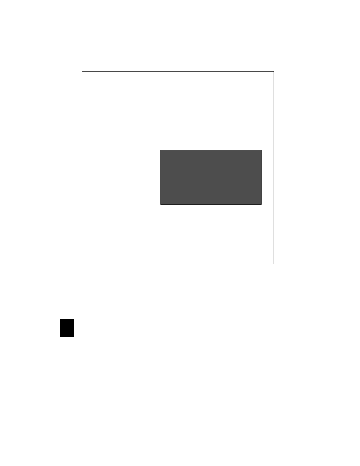
Fill in as much of this portion as you can
Problem type= enhancement,question,bug,crash...
Problem area= hardware, server, document, network,
application, configuration,...
Type of host =
Host OS release=
Window manager=
Boot method= MOP, TFTP, NFS, or PCMCIA
NCD Customer ID= assigned by NCD the first time you send e-mail
User name=
Company/organization=
Title=
Phone number=
FAX number=
E-mail address=
Shipping address=
for example,
for example,
for example,
mwm,host-based mwm
Sun
4.1.3
ncdwm,olwm,local
The first time you send e-mail to
Technical Support, fill out this
customer information section
completely. For subsequent help
requests, you can leave this
information out, supplying only
the NCD Customer ID.
Cut and paste the information displayed in the Console’s Show Version window,
or provide the following information about the X terminal:
Model of terminal=
Memory installed=
NCDware version=
Boot Monitor version=
for example,
for example,
for example,
for example,
HMX
2/4 = 6 total
4.0.100
2.7.0
Provide a detailed description of the problem.
8
30
Page 31

Returning Components
If you have to return a component, follow these steps.
1. Gather the information listed in “Phoning Technical Support.”
2. Contact NCD Service Operations to determine the faulty component and to obtain a Return Authorization Number (RMA).
• e-mail: [email protected]
• phone:(415) 691-7445
3. Once you have obtained an RMA number, package the component
for return.
If possible, use the original cartons and packing materials. If the
original cartons and materials are not available:
• Wrap each component in bubble wrap.
• Place each component in sturdy carton that leaves 4 inches of bubble
wrap and packing material around the component.
If you would rather not pack the component yourself, NCD recommends that you take it to a commercial packing and shipping
company and ask that the content be wrapped according to these
instructions.
4. Mark each return package with the assigned RMA number and
address each package as shown below to avoid problems or
delays:
Customer Service
Network Computing Devices
350 North Bernardo Avenue
Mountain View, CA 94043
RMA
Note
Equipment returned without an RMA number is subject to
delays or may be returned to the sender.
Ethernet Address of Replacement Bases
If a base is replaced, its Ethernet address is different on the
replacement base. You must change system files that contain Ethernet
addresses.
Comments on the Booklet
You can send comments, suggestions, or questions about this booklet
to the NCD Technical Publications Department by Internet e-mail.
Write to [email protected].
31
8
8
Page 32

Guidelines for Productive and Healthy Use of Your X Terminal
You may have rea d or heard of articles which have lin ked prolonged viewing of co mputer video display termin als with eye fatigue,
and prolonged use of computer keyboards and mouse devices with repetitive stress injuries such as carpal tunnel syndrome. One
common example is the syndrome known as “tennis elbow.” Although a conclusive direct causal relationship between computer
use and these adverse health effects has yet to be scientifically proven, NCD recommends that you read and follow these guidelines
in setting up and using your new NCD X terminal.
• Set up your X terminal in a well lit, glare and shadow-free environment.
• Avoid using your X terminal in a position you find awkward or unnatural.
• Select a chair that provides good lower back support. Adjust your chair so that your feet rest flat on the floor with your
thighs in a horizontal position.
• Place your keyboard on a surface so that your wrists are not tilted, or only slightly tilt ed while using the keyboard. Many
people find a comfortable keyboard height is at the same level as their elbows.
• If the height of your work surface cannot be adjusted, position the chair at a comfortable height and use a footrest to place
your feet on a level surface.
• Place your mouse on a surface which is at the same height as your keyboard. Many people find using the mouse and
keyboard within 16" inches of the body is comfortable.
• Avoid resting your arm on your work surface and merely bending your wrist when using your mouse. Consider using a
wristrest to provide a padded surface for your wrists when working with your mouse.
• Place y our display monitor at a comfortable viewing dista nce. Many pe ople fa vor a distan ce of 16" to 28" from their e yes.
Position the screen so that you are not looking up or down at the screen.
• Take breaks to rest your eyes , stretch your muscles, and move around.
• Vary your work patterns so that you alternate working at your X terminal with other tasks that use different muscle groups
and allow you to focus yo ur eyes at different distances.
• See your physician if you experience persistent muscle ache, joint pain, eye fatigue or other discomfort when using your X
terminal.
These are guidelines. What is comfortable for some may not be comfortable for you. You are the only one who can decide if these
guidelines are appropriated for your needs.
What about electromagnetic emissi ons from your monitor?
Many objects we encounter in our everyda y lives produce very low frequency (VLF) and extremely low frequency (ELF) electro-
magnetic emissions. These objects include such common appliances as portable cellular telephones, televisions, toasters, electric
blankets, and video display terminals (VD T) such as the monitor wh ich is part of your X terminal. VDTs, have been the focus of a
growing controversy over the potential health effect of VLF and ELF emissions.
NCD is monitoring this issue and shares the public’s concern over the potential health consequences of exposure to VLF and ELF
emissions from VDTs. To date, the research and testing on this subject is i nconclusive. Moreover, the link, if any between VDT
emissions a nd adverse health effects is unproven a nd the subject of much debate. Stress, postural stra in and poor working conditions are frequently cited in addition to, and instead o f, VDT emissions as posing p otential healt h hazards to frequent users of
VDTs.
The prevailin g professional opin ion to date is that VDTs are safe. NCD products comply with the applicable regul ati ons and standards for electromagnetic radiation set forth by the U.S. Code of Federal Regulations, Underwriters Laboratories, Inc., the Canadian Stan dards A ssociation and the German VDE Standa rd. Whe n and if n ew or ad ditional stand ards are adopted, NCD w ill take
appropriate steps to comply with them.
Even though the preponderance of profession al opinion i s that VDTs are sa fe, som e of our cust omers have asked us fo r informatio n
on how to reduce th eir exposure to VLF and EL F emissions. Although NCD does not endorse the following as having health benefits, the easiest and perhaps most economical and effective measures are to turn off your display when not in use, to position your
display at arm’s length, and to avoid working in areas where you are po sitioned close to the rear of a VDT where the emissions are
strongest. Also, shields are available from third party vendors that reduce glare and electric emi ss ions.
Copyright and Trademarks
The information contained in this document is subject to change without notice. Network Computing Devices, Inc. shall not be
liable for errors contained herein or for inci dental or consequential damages in connecti on with the furnishing, performance, or
use of this material. This document contains information which is protected by copyright. All right are reserved. No part of this
document may be photocopie d, reproduced, or translated t o another language without the pri or written consent of Network Computing Devices, Inc.
Copyright 1995 1996 by Network Computi ng Devices, Inc.
Trademarks
NCD, Network Computing Devices, and Explora are trademarks of Network Comput ing Devices, Inc. XRemote is a regist ered
tradema rk of Network Computin g Devices Inc. LK-401 is a trademark of Digital Eq uipment Corpor ation. Ethern et is a trademark
of Xerox Corporation. UNIX is a regi stered tra demark of UNIX System Laboratories, Inc. Token-Ring, PS/2, and IBM are registered
trademarks of Internationa l Business Machines Corp. TROPIC is a trademark of National Semi-Conductor Inc. PCMCIA is a trademark of PC Memory Card International Association. X Window System is a trademark of X Consortium. SIMM is a trademark of
Wang Laboratories, Inc
.
Revision History
Part Number 9300351 Rev A, August 1995 -- First release of this document
Part Number 9300385 Rev A, November 1995 -- Changed name to Explora
32
 Loading...