


ICS Chartr 200 VNG/ENG
Installation and Startup Guide
Doc. No. 7-26-3000-EN/11
Part No. 7-26-30000-EN

Copyrightnotice
© 2015,2019Natus MedicalDenmark ApS.All rights reserved. ® Otometrics, the OtometricsIcon, AURICAL,MADSEN, Otoscan,
ICSand HORTMANN are registered trademarks of Natus MedicalDenmark ApS in the U.S.A.and/or other countries.
Version release date
2019-05-15 (213483)
Technical support
Please contact your supplier.
2
Otometrics - ICS Chartr 200 VNG/ENG

Table of Contents
1 Introduction
2 Prepare System for Data Collection
3 Prepare Patient for Testing
4 Collect Patient Data
5 Review and Analyze Collected Data
6 Print a Patient Report
7 System Options and Settings
8 Maintenance and Troubleshooting
9 Safety
10 Manufacturer
11 Technical Specifications
12 Installation
5
6
15
18
28
43
48
51
55
58
59
68
Otometrics - ICS Chartr 200 VNG/ENG
3


1 Introduction
ICS Chartr 200 VNG/ENG is indicated for videonystagmography and/or electronystagmography testing for patients with a
complaint of dizziness or imbalance.
The ICS Chartr 200 VNG/ENG Installation and Startup Guide is intended for first time users of the system. It begins with
step-by-step instructions for setting up records, preparing the patient, collecting data, reviewing and analyzing data, and
preparing reports. The Installation Reference section provides information on setting up the hardware.
This guide is organized as follows:
• Prepare System for Data Collection
• Prepare Patient for Testing
• Collect Patient Data
• Review and Analyze Collected Data
• Print a Patient Report
• System Options and Settings
• Maintenance and Troubleshooting
• Safety
• Technical Specifications
• Installation
Once you are comfortable with the basics, take the time to explore the extensive capabilities of the ICS Chartr 200
VNG/ENG system.
1 Introduction
1.1 Intended Use
The ICS Chartr 200 VNG/ENG is a nystagmograph that is intended to measure, record,and display involuntary movements
(nystagmus) of the eyeball.
Otometrics - ICS Chartr 200 VNG/ENG
5
2 Prepare System for Data Collection
2 Prepare System for Data Collection
2.1 Step 1 System Startup
A. Press the Power button on the PC and wait for the Windows® Desktop todisplay.
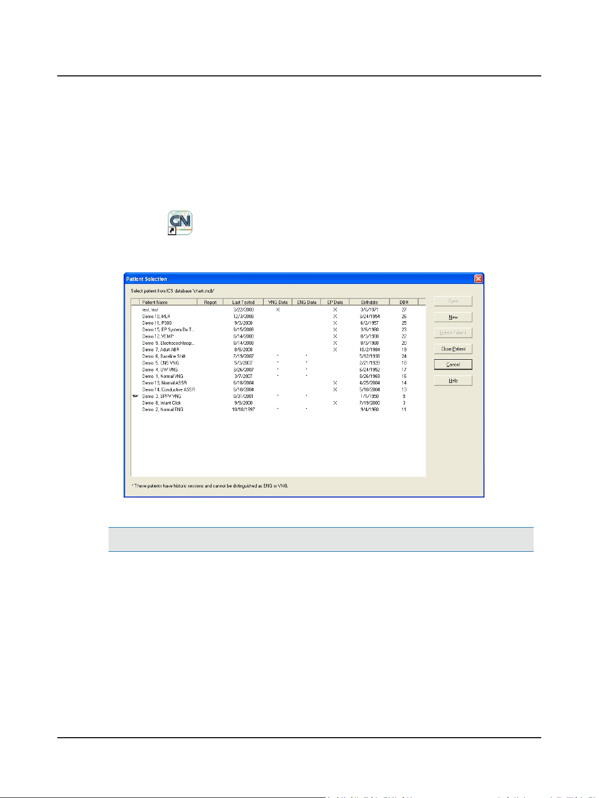
B. Double-click (ICS VNG or ENG icon) to display the Patient Selection dialog. Alternate: Click the Start button on
the Taskbar. Select Programs >Otometrics > Chartr 200 VNG/ENG for Windows.
C. Click New to prepare the system for a new patient record.
Patient Selection Dialog Box
Note• To comply with HIPAA regulations, the ICS Chartr 200 system relies on Windows password protection.
D. Go to Step 2 Start a New Patient Record ► 7
6 Otometrics - ICS Chartr 200 VNG/ENG
2.2 Step 2 Start a New Patient Record
A. Complete the patient information.
2 Prepare System for Data Collection
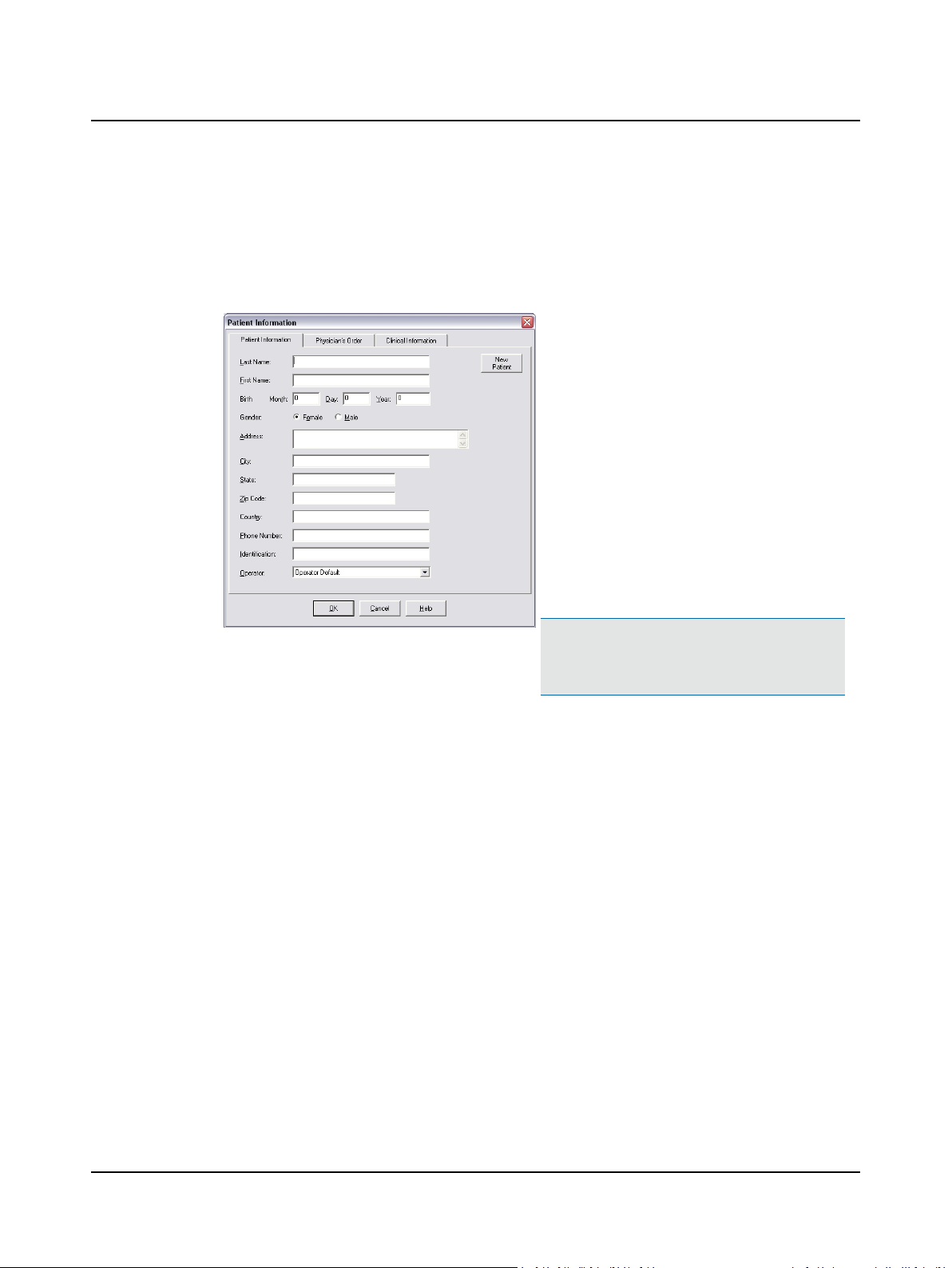
1. Select the Patient Information tab.
2. Type the patient’s
– Last Name [required]
– First Name [required]
– Birth information [required]
3. Select the Gender [required]
4. Type the patient’s
– Address
– City
– State, Zip Code (postal code), Country
– Telephone Number
– Identification (such as a Medical Record Num-
ber, etc.)
5. Click the q and select the Operator. If your name
is not on the list go to Step 5 Add an Operator ►
10.
Patient Information Dialog Box, Patient Information Tab
B. Go to Step 3 Select a Referring Physician and Facility ► 8
Note• Click New Patient to create another
patient record while an existing patient record is
open.
Otometrics - ICS Chartr 200 VNG/ENG
7
2 Prepare System for Data Collection
2.3 Step 3 Select a Referring Physician and Facility
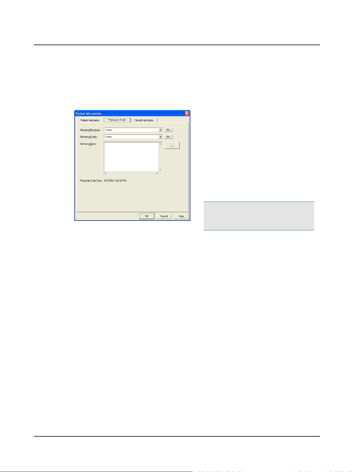
A referring physician can be associated with a patient record. This association is called a Physician Order.
A. Select a Referring Physician and Referring Facility.
1. Click the Physician’s Order tab
2. Click the q and select the Referring Physician.
3. Click the q and select a Referring Facility. If not
4. (optional) Type information about the referral
Note• If this patient was tested previously, click
New Order to start a new physician order for the
patient.
Patient Information Dialog Box, Physician’s Order Tab
If not listed, click Info and go to Step 8 Add a
Referring Physician ► 13.
listed, click Info and go to Step 9 Add a Referring
Facility ► 13
(Referring Notes). This information will appear in
the patient report.
B. Go to Step 4 Answer Clinical Information Questions ► 9.
8 Otometrics - ICS Chartr 200 VNG/ENG
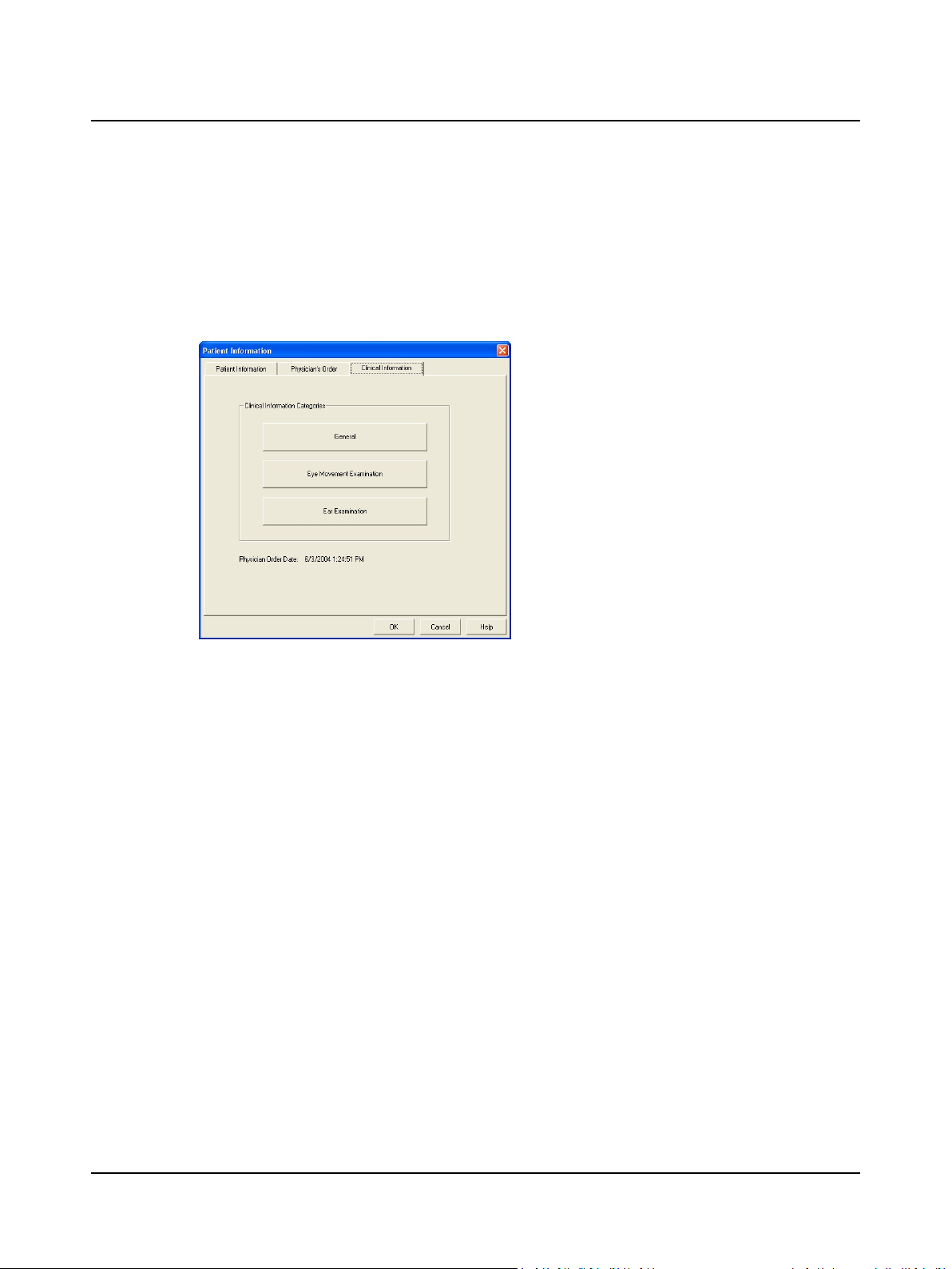
2.4 Step 4 Answer Clinical Information Questions
The clinical information questions seek information about the patient’s general condition, and eye and ear examination
findings. This information can be included in the patient report.
A. Click the Clinical Information tab.
B. Click on a button and answer the questions.
1. Click the Clinical Information tab.
2. Click General and select an option. Click Next to
see another question.
3. Click Eye Movement Examination and select an
option. Click Next to see another question.
4. Click Ear Examination and select an option. Click
Next to see another question.
5. Click the Patient Information tab.
2 Prepare System for Data Collection
Patient Information Dialog Box, Clinical Information
Tab
C. Click Patient Information tab and click OK.
D. Go to Step 5 Add an Operator ► 10 to modify operator information, Step 6 Modify Operator Options ► 11 to modify
operator options, and Step 7 Modify the Test Battery ► 12 to modify the test battery. Go to Step 36 Peak Fre-
quency/GDT Interface ► 50 to modify the German interface.
E. Go to Step 10 Study the Main Window ► 14.
Otometrics - ICS Chartr 200 VNG/ENG
9
2 Prepare System for Data Collection
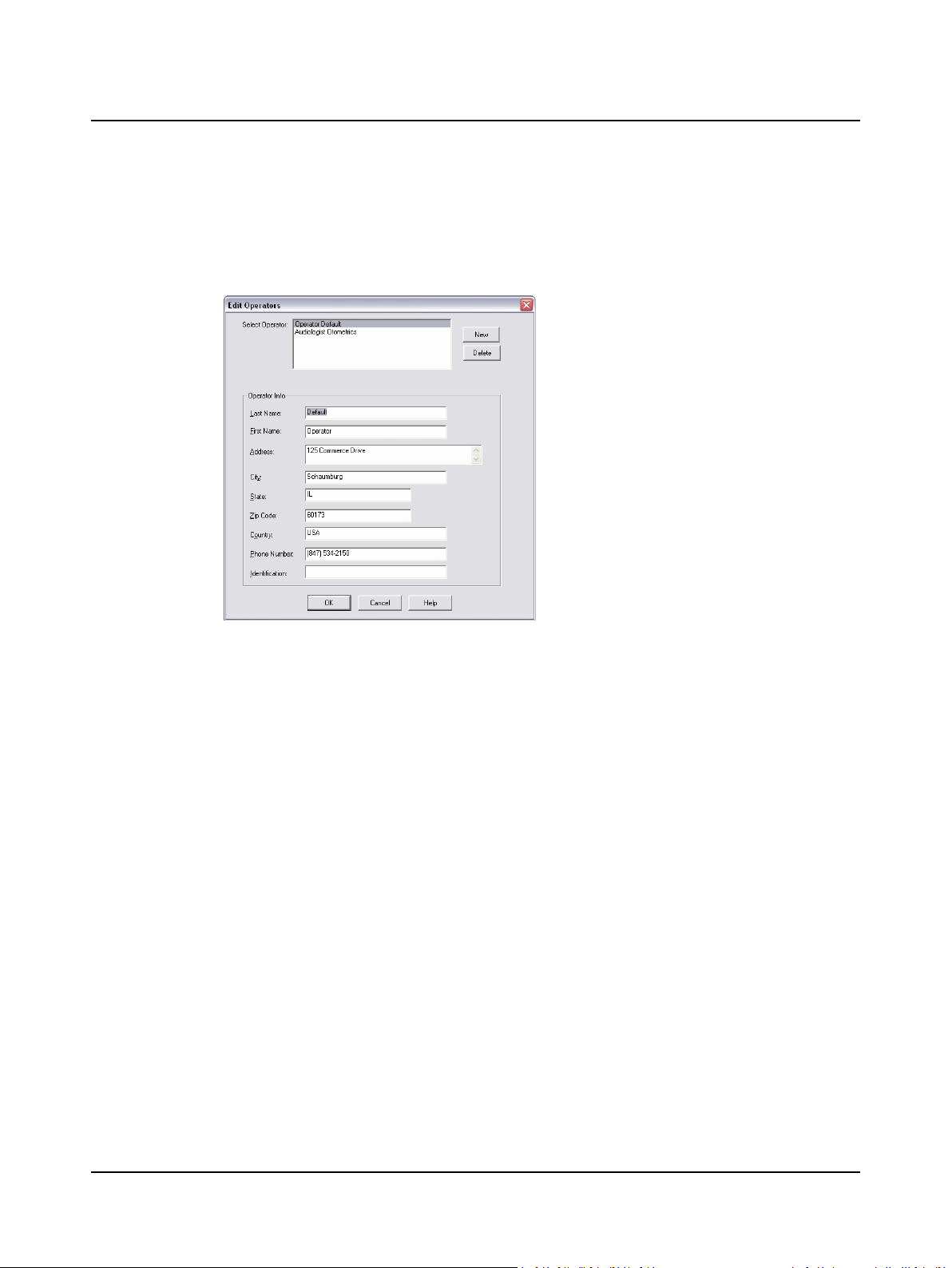
2.5 Step 5 Add an Operator
A. Select Edit > Operator Info.
B. Complete the operator information.
1. Click New
2. Type your:
– Last Name [required]
– First Name [required]
– Address
– City
– State, Zip Code (postal code), Country
– Telephone Number
– Identification (such as a work ID, etc.)
3. Click OK
Edit Operators
C. Go to Step 2 Start a New Patient Record ► 7 or click F2 New Patient.
10 Otometrics - ICS Chartr 200 VNG/ENG
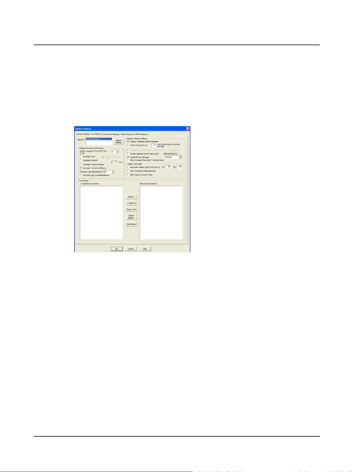
2.6 Step 6 Modify Operator Options
Each operator may establish collection, review, and report settings. These settings will be in effect each time the operator’s name is selected.
A. Select Edit > System Options. Select the Operator Settings/Test Battery tab.
B. Customize the Collection, Review, and Report Settings.
System Options, Operator Settings/Test Battery Tab
2 Prepare System for Data Collection
1. Click the Operator Settings / Test Battery tab
2. Select an operator. If your name is not on the list,
go to Step 5 Add an Operator ► 10.
3. Select the Settings Shared by All Operators:
– Beats Averaged in Peak SPV Calc [x]
– Automatic Save
– Caloric Countdown Timer [x secs]
– Automatic Analysis
– Automatic Analysis Display
– Automatic Waveform Filtering
– Maximum Saccade Latency [x]
– Omit GN Logo from Printed Report
4. Select the Operator Specific Settings:
– Require Calibration Before Collection
– Center Tracings Every [x] secs (except
gaze, saccade, tracking)
– Footswitch/Irrigator Buttons – Center
waveform during collection
– Display Lightbar Center Fixation Light
– Lightbar Brightness [Low, Medium, High]
– Enable Distance Ranger
– Show Averaged Saccade and Tracking Val-
ues
5. Select Caloric Test Only Settings:
– Automatic Fixation Light On [x] /Off [x]
(secs)
– Show Directional Preponderance
– Show Right Ear Data in Red
C. Click OK and go to Step 7 Modify the Test Battery ► 12.
Otometrics - ICS Chartr 200 VNG/ENG
11
2 Prepare System for Data Collection
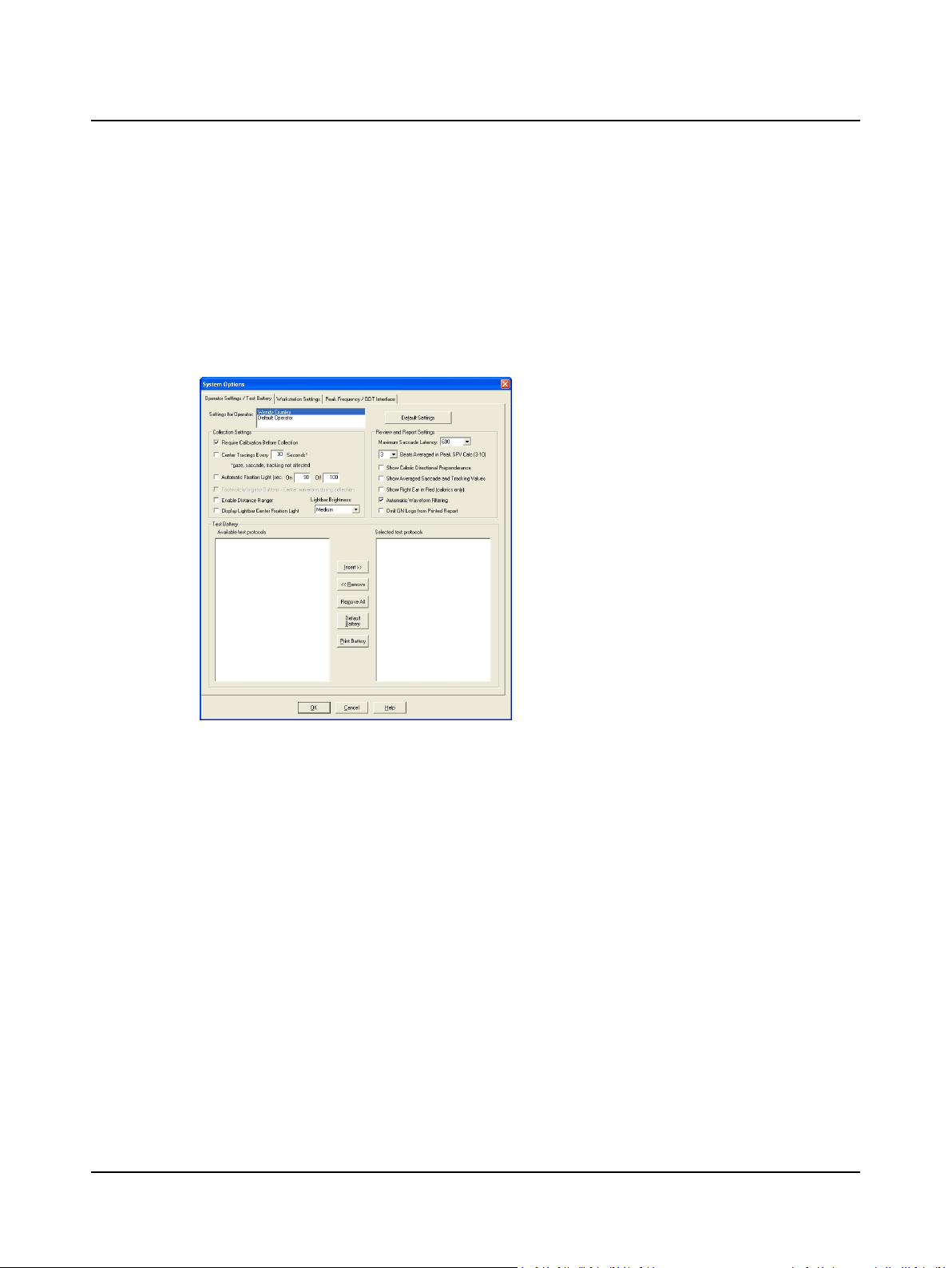
2.7 Step 7 Modify the Test Battery
In addition to establishing collection, review, and report settings, each operator may create a customized test battery (testing sequence).
A. Select Edit > System Options. Select the Operator Settings/Test Battery tab.
B. Arrange the test protocols in the sequence you want to conduct the tests. The Available test protocols (on the left)
lists all possible tests. The Selected test protocols (on the right) lists the operator’s test sequence. Note: if the hardware is not turned on, the Test Battery Lists will be empty because the available protocols are hardware dependent.
1. Click the Operator Settings / Test Battery tab.
2. Select an operator. If your name is not on the list, go
to Step 5 Add an Operator ► 10
3. Click on a + to show the protocols listed under a procedure.
4. Click on a protocol or procedure to highlight it.
5. Click the Insert >> button to move the highlighted
protocol to the selected test protocols (test battery)
box.
Click the <<Remove removebutton to delete a highlighted protocol or procedure from the test battery.
Click the Remove All button to delete all of the protocols and procedures from the test battery.
Click the Default Battery button to use the ICS
System Options, Operator Settings/Test Battery Tab
default test battery.
Installation Note:
If your facility has a different protocol than what is set up in the default test battery, it is recommended that when you first
install the system, you set up a facility default operator test battery. Then add all other operators, and they will inherit the
default test battery. If desired, each operator’s test battery can be further customized.
C. Click OK and go to Step 10 Study the Main Window ► 14.
12 Otometrics - ICS Chartr 200 VNG/ENG
2.8 Step 8 Add a Referring Physician
Referring physician records are available to all operators. If the referring physician’s name is not on the list, create a new
record.
A. Click New to start a new record and type the requested information.
2 Prepare System for Data Collection
1. Click New.
2. Type the physician’s:
– Last Name [required]
– First Name [required]
– Address
– City
– Zip Code (postal code)
– Country
– Identification (work ID, etc.)
– Telephone number (up to 5)
– Fax number
– Email address
Referring Physician Information Dialog Box
B. Click OK to save the record and return to the Patient Information dialog.
C. Go to Step 3 Select a Referring Physician and Facility ► 8 (item A3 Referring Facility).
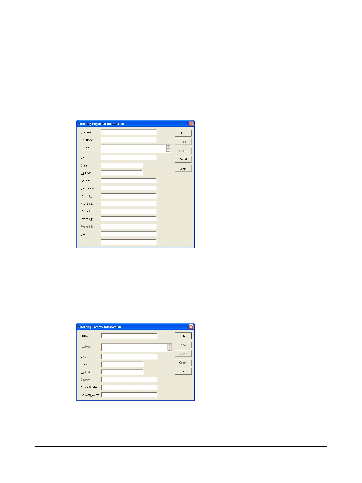
2.9 Step 9 Add a Referring Facility
Referring facility records are available to all operators. If the referring facility’s name is not on the list, create a new record.
A. Click New to start a new record and type the requested information.
Referring Facility Information Dialog Box
3. Click OK.
1. Click New.
2. Type the facility information:
– Name [required]
– Address
– City
– State
– Zip Code (postal code)
– Country
– Phone Number
– Contact Person
3. Click OK.
B. Click OK to save the record and return to the Patient Information dialog.
Otometrics - ICS Chartr 200 VNG/ENG
13
2 Prepare System for Data Collection
C. Go to Step 3 Select a Referring Physician and Facility ► 8 (item A4 Referring Notes).
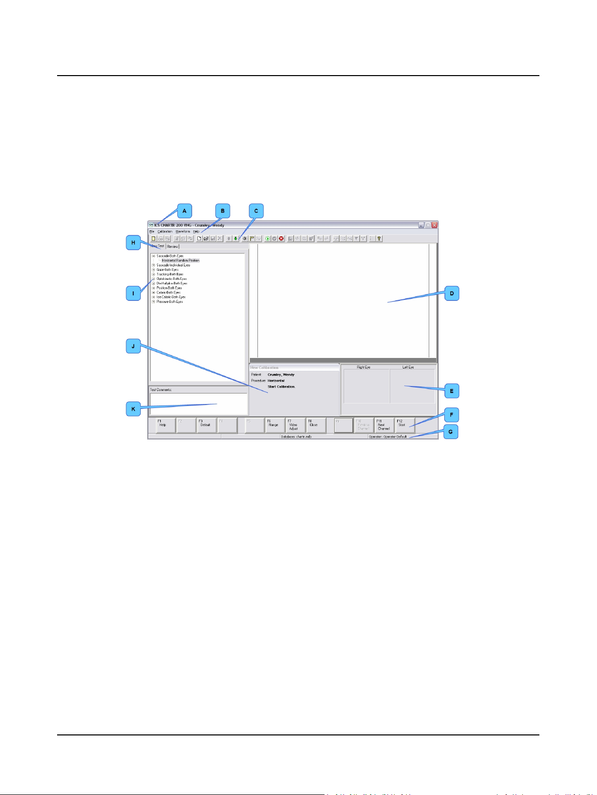
2.10 Step 10 Study the Main Window
The Main Window is the primary workspace. When a patient record is open, it contains patient test and analysis data.
A. Study each area of the Main Window.
VNG/ENG Main Window with Patient Data
A. Title bar
B. Menu bar
C. Toolbar
D. Waveform Display Area
B. ENG: go to Step 11 ENG – Apply Electrodes ► 15.
VNG: go to Step 13 VNG – Place Goggles on Patient ► 17.
E. Eye image area
F. Function keys
G. Status bar
H. New Test & Review tabs
I. New Test/Review area
J. Information area
K. Text comments
14 Otometrics - ICS Chartr 200 VNG/ENG
3 Prepare Patient for Testing
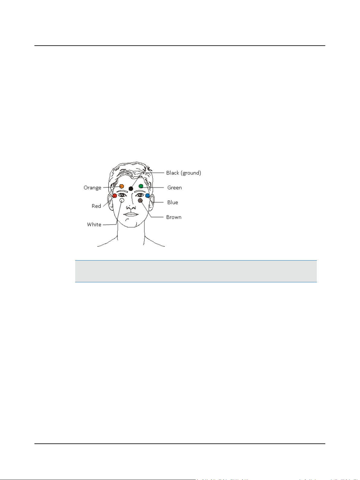
3.1 Step 11 ENG – Apply Electrodes
The ENG system records 2 or 4 channels of eye movement information. Channel designations relate to electrode placement both on the face and in the electrode patient cable.
A. Place electrodes on the patient as needed for 2 or 4 channel collection.
3 Prepare Patient for Testing
Channel Electrode cable
Connections
red – blue
Horizontal both (HB)
Vertical right (VR) orange – white
Vertical left (VL) orange – white
Horizontal right (HR) red – black
Horizontal left (HL) blue – black
Normal Electrode Placement (4 channels)
Note• For 2 channel recordings, use the green and brown openings on the patient cable for the vertical chan-
nel. The green and brown electrodes can be placed above and below the right or left eye.
B. Connect the electrode leads to the designated color on the patient cable.
C. Go to Step 12 ENG – Check Electrodes ► 16.
Otometrics - ICS Chartr 200 VNG/ENG
15
3 Prepare Patient for Testing
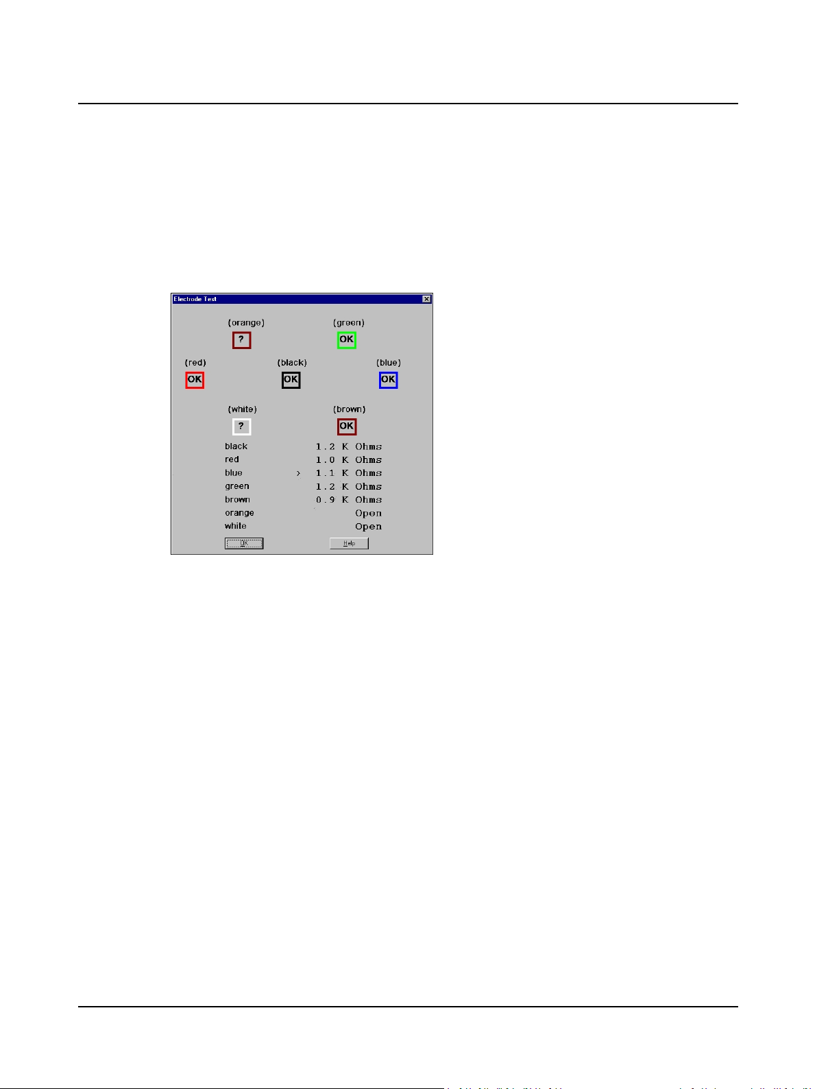
3.2 Step 12 ENG – Check Electrodes
Impedance is measured at each skin-electrode interface. A question mark (?) indicates an unacceptable electrode connection.
A. Select a protocol in the New Test tab, then click F7 Electrode Test .
B. Read the status of each active electrode and channel.
1. Check each electrode connection.
2. Check mV or K Ohm values.
3. Click OK.
Electrode Test Dialog Box
C. Reapply electrodes or leads as needed.
D. Click OK to close the dialog.
E. Go to Step 16 Check the Range ► 21.
16 Otometrics - ICS Chartr 200 VNG/ENG
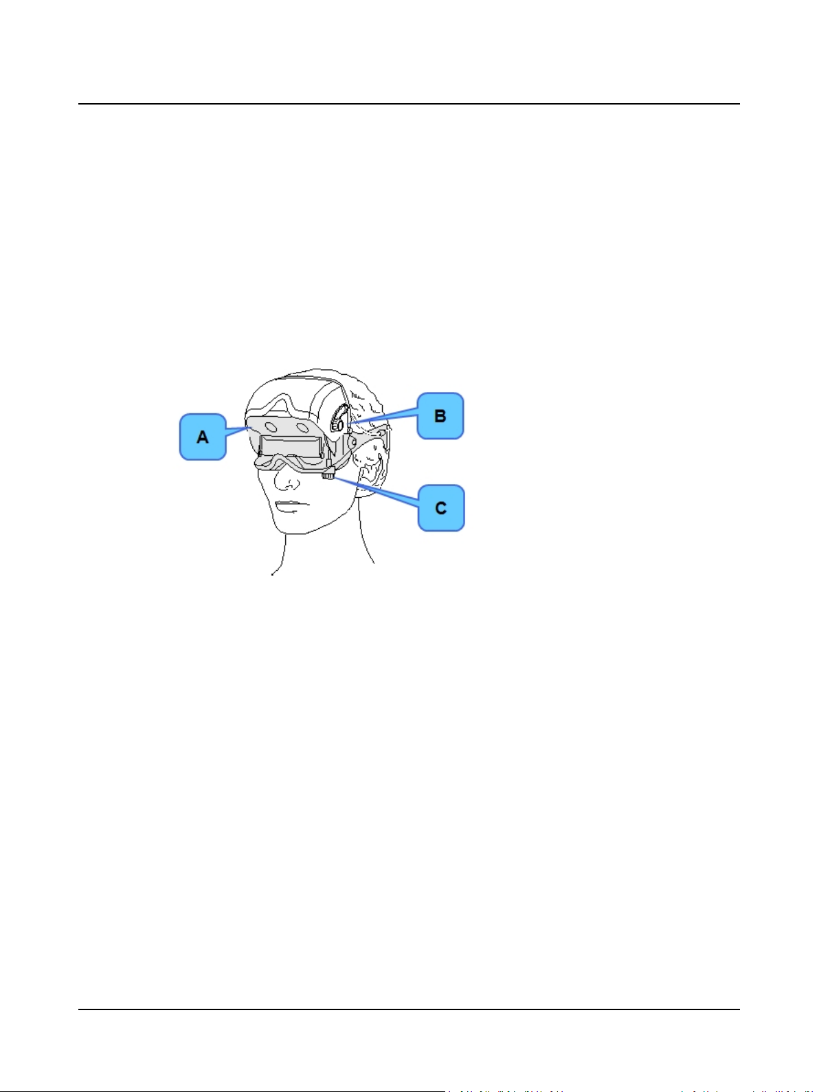
3.3 Step 13 VNG – Place Goggles on Patient
The video goggles contain video camera lenses and mirrors. The video image displays on the monitor. For more information about how the goggles function, refer to the User Manual.
A. Place the VNG video goggles on the patient. Proper placement of the goggles is very important. Refer to the User
Manual for detailed instructions.
1. Make sure the mirror is clean. Avoid touching the mirror while placing the goggles on the patient.
2. Place the goggles on the bridge of the patient’s nose.
3. Make sure the back head strap is over the back of the patient’s head below the inion (bump on the lower part of
the skull.) Replace worn head straps. See the User Manual.
3 Prepare Patient for Testing
A. Fine focus adjustment knob. Turn this knob
to fine tune (focus) the eye images in the
Video Adjustments dialog box. Focus adjustment may be needed if the patient has deepset or protruding eyes.
B. Horizontal positioning knob. Turn knob to
adjust the horizontal position of the eyes.
Adjustment may be needed if the patient has
wide-set or close-set eyes.
C. Vertical positioning knob. Turn knob to adjust
the vertical position of the eyes.
VNG Video Goggles
B. VNG: Go to Step 14 VNG – Center and Focus the Video Image ► 18 to adjust the video image.
C. Go to Step 17 Select a Protocol ► 22.
Otometrics - ICS Chartr 200 VNG/ENG
17
4 Collect Patient Data
4 Collect Patient Data
4.1 Step 14 VNG – Center and Focus the Video Image
A. Click the New Test tab on the Main Window and choose the eye(s) to be tested.
B. Click F7 Video Adjust to display the Video Adjustments dialog.
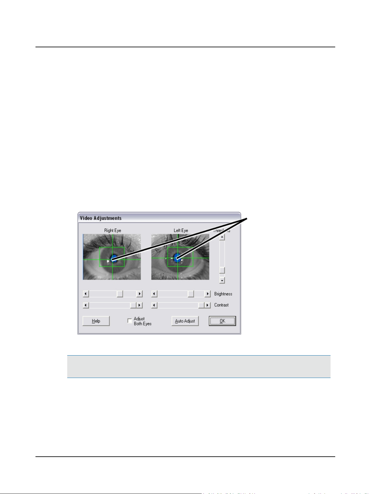
C. Adjust the eye image.
1. Ask the patient to look straight ahead.
2. Move the goggles to center and level the pupils. Make sure the pupils are inside the boxes, as close to the center
as possible.
3. Tighten the back head strap until the goggles are snug. The goggles should fit securely so they will not move during positional testing.
4. Straighten and tighten the top head strap to assist in positioning the goggles on the patient’s face and positioning
the pupils in the box.
5. Use the goggle horizontal
and vertical positioning
knobs to center each pupil
image.
6. Use the goggle focus knobs
to focus each image.
7. Repeat as needed to center
the pupils and focus the eye
images.
Video Adjustments Dialog Box, Both Eyes
Note• For monocular testing, only the selected eye will be visible. If testing both eyes, make sure both eye images dis-
play, both pupils are centered, and both eye images are in focus.
D. Use the goggle controls (knobs) if needed to align the patient’s eyes and focus the image while the patient looks
straight ahead.
18 Otometrics - ICS Chartr 200 VNG/ENG
Caution• Do not over tighten the knobs as this may damage the adjustment pieces that hold the mirror.
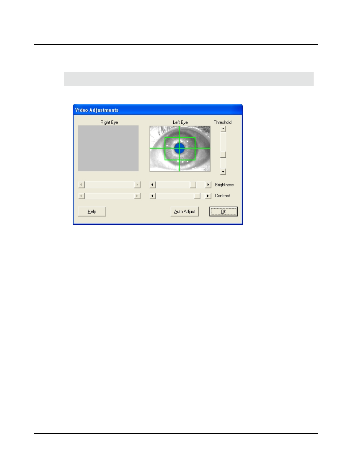
E. Click the Auto Adjust button to move the slides automatically until the pupils begintracking.
4 Collect Patient Data
Video Adjustments Dialog Box, One Eye
F. Go to Step 15 VNG – Fine Tune the Video Image ► 20.
Otometrics - ICS Chartr 200 VNG/ENG
19
4 Collect Patient Data
4.2 Step 15 VNG – Fine Tune the Video Image
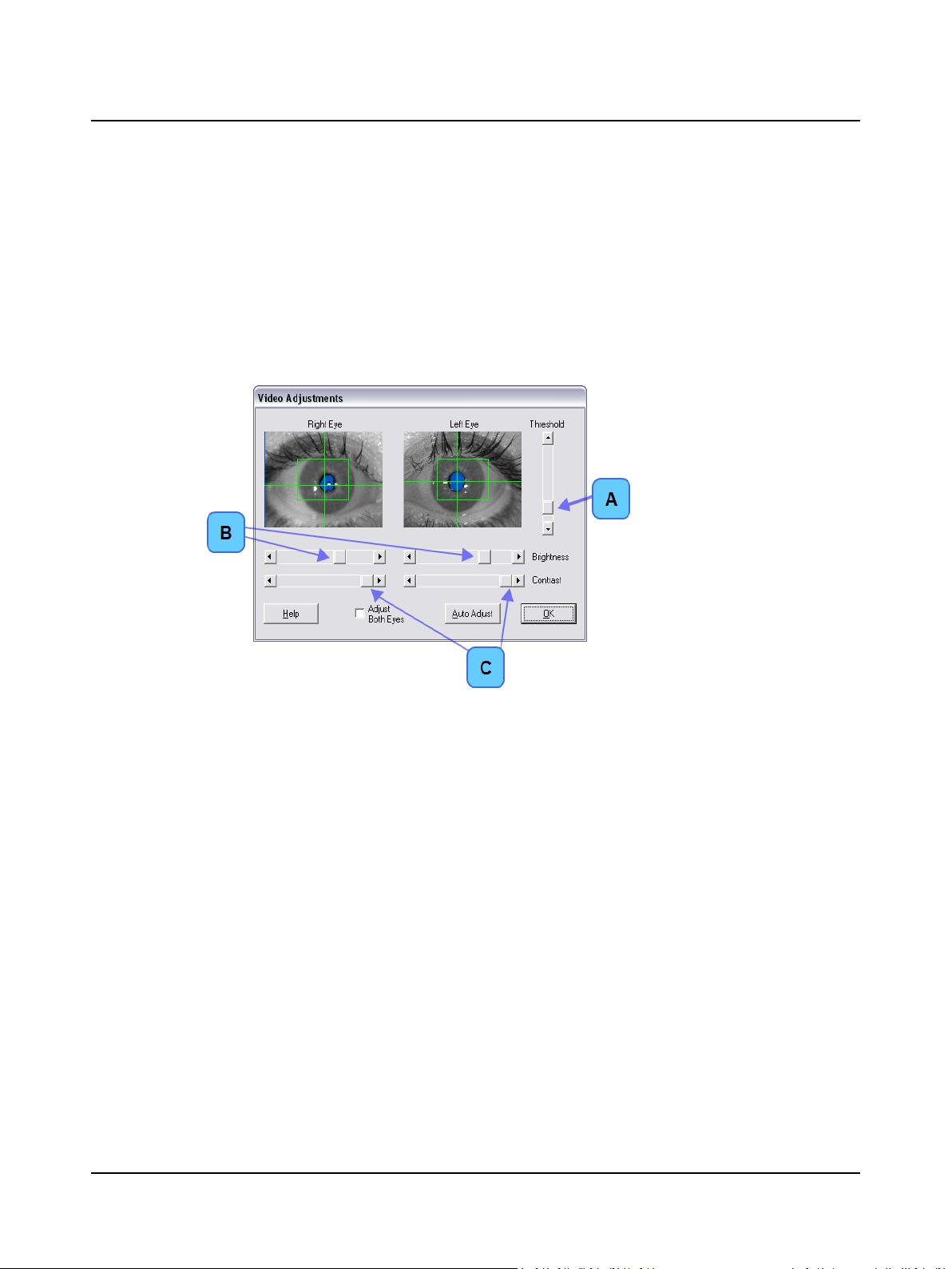
A. Use the software controls to fine tune the video image for each eye, if needed.
1. Only the pupil should be blue. There should be none or a minimal amount of blue surrounding the eye (i.e., eyelashes). The crosshair will automatically go where the blue resides, and this should only be the pupil.
2. If the room is very light, close the goggle cover during these adjustments.
3. If needed, move the sliders to manually adjust the threshold, brightness, and contrast to improve the quality of
the tracking.
1. Drag the Threshold (A) slider
slightly up or down until the
pupil tracks properly.
2. Select Adjust Both Eyes to
change brightness and contrast for both eyes at the
same time
3. Drag the Brightness (B) and
Contrast (C) sliders until the
image is clear and good
tracking is obtained.
Video Adjustments Dialog Box
B. Ask the patient to look left, right, up, and down. Verify that the crosshairs track both eyes.
C. Click OK to accept the video image settings.
D. Go to Step 17 Select a Protocol ► 22.
20 Otometrics - ICS Chartr 200 VNG/ENG

4.3 Step 16 Check the Range
A range sensor provides a continuous display of patient-to-light bar distance. The acceptable range during testing is 3 feet 8
inches to 4 feet 4 inches (111.8 cm to 132.1cm). If a patient is “out of range” for more than 10% of a test, a message displays at the end of the test.
A. Click the New Test tab on the Main Window and select a protocol.
B. Position the patient in front of the light bar.
C. Click F6 Range to activate the range sensor.
Range Dialog Box
4 Collect Patient Data
Range:
• Distance – in feet / inches and centimeters
• Over Range
• Under Range
During a test, range status updates every 3 seconds and displays in the Information Area of the Main Window.
D. Click OK to close the dialog and exit the Interpretation Assistant.
E. Go to Step 17 Select a Protocol ► 22.
Otometrics - ICS Chartr 200 VNG/ENG
21

4 Collect Patient Data
4.4 Step 17 Select a Protocol
A. Click the New Test tab on the left side of the Main Window.
New Test tab (A)
Procedure (B)
Protocol (C)
Click on a + sign to show the hidden protocols.
Click on a – sign to show only the procedure name.
New Test Tab
B. Choose the eye(s) and the protocol prior to calibrating.
1. Choose the eye(s) to be tested on the toolbar.
Eye Buttons on Toolbar
2. Click on a protocol to select it.
C. Go to Step 18 Calibrate the Patient ► 23.
22 Otometrics - ICS Chartr 200 VNG/ENG

4.5 Step 18 Calibrate the Patient
The horizontal channel should always be calibrated if possible. The vertical channel is more difficult for patients, and it is
acceptable to use F3 Default Calibration. To perform an individual eyes calibration, select an individual eyes protocol.
A. Make sure the light bar is positioned properly (horizontally or vertically) and the patient is 4 feet (1.2 m) from the bar.
B. Select a protocol on the New Test tab on the Main Menu.
C. Click F5 Calibrate to access the calibration mode. (Ask the patient to follow the dot of light on the light bar without
moving his/her head.) The targets are ±10°. They do not extend to the end of the light bar.
D. If using Monocular VNG, click F9 Switch Eye to select the eye to be tested. The eye that is grayed out is the cur-
rently selected eye.
4 Collect Patient Data
1. Click F9 Switch Eye to change
the selected eye.
2. View selected protocol and selec-
ted eye (A).
Main Window, Calibration Mode, Monocular VNG
E. Click F12 Start. The system automatically adjusts the gain and offset of the eye signal to match the target. When the
two tracings match (in size), press F12 Accept and allow 2 to 3 more cycles to run to verify the accuracy of the calibration.
Calibration Waveforms
Otometrics - ICS Chartr 200 VNG/ENG
Accept Calibration Marker (A)
VNG Note: The Video Eye Display dialog
will display
23

4 Collect Patient Data
F. Click F12 Stop.
Note• The system accepts the calibration or displays this error message:
Technical Comment
G. Use F5 Enlarge and F6 Shrink to adjust the calibration if you are unable to recalibrate or recollect data. Enlarge will
increase the size of the waveform, and Shrink will reduce it. These adjustments will apply only to this test. Press F3
Original Calibration to remove the adjustments.
H. Click F12 Save to save the calibration.
I. Click F10 Next Channel or F11 Previous Channel to calibrate a different channel.
J. Click F9 Done to return to the test mode.
K. Go to Step 19 Start Data Collection ► 25.
• Click OK to calibrate the system
before running the selected test.
Then press F4 Resume and repeat
D through F.
• Click Use Default Calibration to
calibrate the system using the
default calibration (applies only to
this test). Then press F4 Resume
and repeat D through F.
24 Otometrics - ICS Chartr 200 VNG/ENG

4.6 Step 19 Start Data Collection
The operator may start and stop data collection at any time. A test may be repeated and saved. The first test is designated
as primary, the others are secondary. Primary test results will be included in the patient report (see Step 32 Print the
Report ► 46) and the primary designation may be reassigned during a review (see Step 22 Reassign Primary Test Status ►
29).
The suggested minimum collection time is 1 minute 30seconds for Saccade and Tracking tests and approximately 2
minutes for Caloric tests. Other tests should be run for 20 seconds or longer, if needed.
If your system uses a Otometrics caloric stimulator, you may use the caloric handset or footswitch to start a test. Selecting
a caloric test on the New Test tab automatically selects the cool or warm temperature on the stimulator.
• ENG Note: After a test is started, press the handset or footswitch to remotely center a tracing.
• VNG Note: After a test is started, press the handset or footswitch to remotely start or restart the video recording.
A. Click on a protocol on the New Test tab.
B. Click F12 Start to begin data collection.
C. Use the function keys during data collection.
4 Collect Patient Data
Function Keys, During Data Collection
F2 Event
F3 Eyes Open
F4 Vision Denied
F5 Center
F7 Hide Wave
F8 Show Wave
F9 Cancel Test
F10 Overlap Waves
F11 Spread Waves
F12 Stop/Save
Place an Event (E) marker on the tracing.
Place an Eyes Open (EO) marker on the tracing.
Place a Vision Denied (VD) marker on the tracing.
Move the tracing to the center of the waveform area.
Display the selected wave.
Do not display the selected wave.
Stop data collection without saving test results.
Stack (overlap) tracings in the waveform area.
Spread all tracings evenly in the waveform area.
Stop the test./Stop data collection and save the results.
VNG Note: Go to Step 20 VNG – Record Video Image ► 26 to record eye images during data collection.
D. Press F12 Stop.
E. Press F12 Save to save the collected data and advance to the next protocol.
F. Repeat A through E for each protocol.
G. VNG: go to Step 20 VNG – Record Video Image ► 26.
ENG: go to Step 21 Display Collected Data ► 28.
Otometrics - ICS Chartr 200 VNG/ENG
25

4 Collect Patient Data
4.7 Step 20 VNG – Record Video Image
ICS Chartr 200 VNG/ENG records up to 2 minutes of eye movement video for each test and saves the recording with the
patient record. A small camera icon next to a patient name in the Patient Selection dialog or protocol in the Review tab
indicates the existence of a video recording.
Video recording may be started at any time during data collection. The video controls are in the Video Recording Control
dialog.
A. Click the New Test tab and select a protocol.
B. Click F12 Start to begin data collection and display the Video Recording Control dialog.
C. Click the Record button to start the video recording.
Note• You may also use the optional footswitch to start or restart a video recording.
1. Click the Record button (A).
Note• The system puts an
event marker (V) on the tracing
at the point video recording
begins.
Video Recording Control Dialog Box, Both Eyes
Video Recording Control Dialog Box, One Eye
2. Note available recording time
(B).
1. Click the Record button (A).
Note• The system puts an event
marker (V) on the tracing at the
point video recording begins.
2. Note available recording time (B).
26 Otometrics - ICS Chartr 200 VNG/ENG

D. Monitor video collection activity.
Video Recording Control Dialog Box (Recording)
E. Click the Stop button.
F. Click F12 Save to save the collected data and video recording.
G. Go to Step 21 Display Collected Data ► 28.
4 Collect Patient Data
1. Monitor right and left eye movement (A).
2. Monitor remaining time (B).
Click Restart button to discard
any recorded video and to begin
video recording.
Click Stop button to stop
recording video.
Otometrics - ICS Chartr 200 VNG/ENG
27

5 Review and Analyze Collected Data
5 Review and Analyze Collected Data
5.1 Step 21 Display Collected Data
A. Click the Review tab.
B. Select a Physician Order date and Session.
1. Click the q and select a date.
2. Expand a session (A).
3. Click on a protocol to select it
(B).
Click a + sign to expand a list.
Click a – sign to collapse a list.
Bold text indicates primary status (results will be included in the patient
report). To change the status, go to
Step 22 Reassign Primary Test Status
► 29.
Review Tab
C. Go to Step 23 Reposition Waveforms ► 30.
28 Otometrics - ICS Chartr 200 VNG/ENG

5.2 Step 22 Reassign Primary Test Status
When a test is run more than once during a test session, the system assigns primary status to the first test run and secondary status to the others. Only primary test results are included in the patient report and only the four bolded caloric
tests are included in the caloric summary display and the calculations.
A. Select the Review tab and click on a secondary (not bold) protocol.
B. Select Test > Assign Primary from the Menu bar.
5 Review and Analyze Collected Data
C. Make sure the protocol is now bold text. Repeat A and B, if needed.
D. Go to Step 23 Reposition Waveforms ► 30.
Otometrics - ICS Chartr 200 VNG/ENG
29

5 Review and Analyze Collected Data
5.3 Step 23 Reposition Waveforms
During review, you may view and manipulate collected waveforms.
A. Select and move a waveform.
Waveform Display Area
1. Use the scroll bar to view the entire
waveform (A).
2. Click on a waveform handle (B).
3. Click and drag (or press the äã keys)
to move selected waveforms up or
down.
The letter on Waveform Handle indicates
the channel:
H Horizontal
V Vertical
ST Stimulus
HR Horizontal Right
HL Horizontal Left
VR Vertical Right
VL Vertical Left
A gray handle indicates data was collected
for the channel but not displayed.
Displayed Time indicates the time for
the section of waveform displayed on
the screen (A).
Information Area During Collection
B. Go to Step 32 Print the Report ► 46 to print a waveform or group of waveforms.
C. Go to Step 24 Review a Calibration ► 31.
30 Otometrics - ICS Chartr 200 VNG/ENG

5.4 Step 24 Review a Calibration
A. Click on a test on the Review tab.
B. Press F8 Review Calib.
Saved Calibration
5 Review and Analyze Collected Data
The calibration data is saved with a test
and can be reviewed. Each calibration
record contains the last 10 seconds of the
calibration. The age (calculated from the
end of the calibration to the beginning of
the test) displays in the Main Window
Information Area (ENG only).
(A) Indicates when operator accepted the
calibration.
C. Use the function keys to work with the calibration waveforms.
Function Keys, Calibration Review
F3 Original Calib.
F5 Enlarge
F6
Shrink
F7 Up
F8 Down
F9 Close
F12 Save
D. Go to
Step 25 Analyze Saccade Test Results ► 32,
Step 26 Analyze Sinusoidal Tracking ► 34,
Step 27 Analyze Slow Phase Velocity (SPV) Measurements ► 36 or
Step 28 Analyze Caloric Test Results (Pod and Butterfly Views) ► 39.
Return to the original calibration.
Increase the gain of the waveform.
Reduce the gain of the waveform.
Move selected wave up.
Move selected wave down.
Close any adjustments.
Save calibration and return to test data.
Otometrics - ICS Chartr 200 VNG/ENG
31

5 Review and Analyze Collected Data
5.5 Step 25 Analyze Saccade Test Results
A. Click the Review tab and select a Saccade test.
B. Click F12 Analysis.
C. Select Analysis > Averaged, Raw, or Averaged & Raw to see different views of thedata.
1. Click an option to select it (A).
Analysis Menu
D. Use the function keys to work with the results.
Function Keys, during Saccade Review and Analysis
F2 Reanalyze
F3 Delete Analysis
F5 Enlarge
F6 Shrink
F7 Up
F8 Down
F9 Close Close Analysis
F10 Previous Saccade
F11 Next Saccade
F12 Save
Discard the current results.
Remove the outlined saccade.
Increase the gain of a tracing in relation to the target.
Reduce the gain of a tracing in relation to the target.
Move selected wave up.
Move selected wave down.
Move to previous saccade.
Move to next saccade.
Save analysis and return to Review mode.
32 Otometrics - ICS Chartr 200 VNG/ENG

Saccade Analysis, Raw and Averaged Values
5 Review and Analyze Collected Data
Click on a data point (A) to move
the tracing (B) to correspond with
the analysis result.
Amplitude – eye movement (in
degrees) between the initial position and the first stop.
Accuracy– amplitude of a saccade
divided by the amplitude of target
movement; expressed as a percent.
Peak Velocity – maximum velo-
city reached in a saccadic movement.
Latency – time between stimulus
movement and the first eye movement
The shaded area is the abnormal
area.
Notes:
• The saccade being examined corresponds with the outlined data point ( ) in the Velocity, Accuracy, and Latency windows.
• Use the waveform handle on the Amplitude chart to move the waveform up or down.
• The shaded areas on the Peak Velocity, Accuracy, and Latency charts represent normative data. Use this information to
compare the averaged responses.
E. Click F12 Save to save the analysis.
F. Go to Step 26 Analyze Sinusoidal Tracking ► 34,
Step 27 Analyze Slow Phase Velocity (SPV) Measurements ► 36 or
Step 28 Analyze Caloric Test Results (Pod and Butterfly Views) ► 39.
Otometrics - ICS Chartr 200 VNG/ENG
33

5 Review and Analyze Collected Data
5.6 Step 26 Analyze Sinusoidal Tracking
A. Click the Review tab and select a Tracking test.
B. Click F12 Analysis.
C. Select Analysis > Averaged, Raw, or Averaged & Raw to see different views of thedata.
Click an option to select it (A).
Analysis Menu
D. Use the function key options to work with the results:
Function Keys during Tracking Review and Analysis
F2 Reanalyze
F3 Delete Analysis
F5 Enlarge
F6 Shrink
F7 Up
F8 Down
F9 Close Close Analysis
F10 Previous Cycle
F11 Next Cycle
F12 Save
Discard the current results.
Remove the outlined cycle.
Increase the gain of a tracing in relation to the target
Reduce the gain of a tracing in relation to the target.
Move selected wave up.
Move selected wave down.
Move to previous cycle.
Move to next cycle.
Save analysis and return to Review mode.
34 Otometrics - ICS Chartr 200 VNG/ENG

Sinusoidal Tracking Analysis, Raw and Averaged Values
E. Click F12 Save.
F. Go to Step 28 Analyze Caloric Test Results (Pod and Butterfly Views) ► 39.
5 Review and Analyze Collected Data
1. Click on a data point (A) to move
the tracing (B) to correspond with
the analysis result.
The shaded area on the Tracking Gain
chart represents normative data. Use
this information to compare the averaged responses.
The shaded area is the abnormal area.
Otometrics - ICS Chartr 200 VNG/ENG
35

5 Review and Analyze Collected Data
5.7 Step 27 Analyze Slow Phase Velocity (SPV) Measurements
A. Click the Review tab and select a Caloric or other test to analyze nystagmus.
B. Press F12 Begin to measure the slow phases and plot them on the lower chart. The number of beats analyzed displays
in the Information area.
C. Use the function keys to work with the results:
Function Keys, during SPV Analysis
F2 Reanalyze
F4 Pods - Butterfly
F5 Locate Peak
F6 Set Peak
F7 Delete
F8 Insert
F9 Close Close Analysis
F10 Previous Beat
F11 Next Beat
F12 Save
Clear previous analysis and begin a new analysis.
Display pod (summary) and butterfly view of caloric analysis.
Identifies the second in time with the fastest average
value.
Computes the average of the highest SPVs in the 10second window at the current cursor location.
Delete the SPV beat measurement.
Accept a new SPV value for the beat.
Move to previous beat.
Move to next beat.
Save analysis and return to Review mode.
D. (Optional) Measure the slope of a beat manually.
SPV Analysis
1. Select a beat (A):
– Click and drag the scroll bar or
press the áâarrow keys to
move through the tracing (B).
– Click F10 Previous Beat and
F11 Next Beat to move
through the tracing.
– Click on a beat in the lower
chart or click in the upper chart
to move to that section on the
tracing.
2. Click F7 Delete to delete artifactual
beats
36 Otometrics - ICS Chartr 200 VNG/ENG

5 Review and Analyze Collected Data
Note• The vertical cursor represents the same point in time as the vertical cursor in the lower chart and exactly
bisects the slow phase of the nystagmus being measured.
Vertical cursor (A).
3. Adjust the slope of the
velocity measuring line to
measure the slow phase of
a beat:
– Press the ãäarrow
keys to raise and lower
the line
– Press Ctrl +á and
Ctrl +â to change the
angle of the line.
– Press F8 Insert to
enter the new SPV
value.
Measuring SPV
SPV Analysis with Peak Selected
Caloric Peak values are represented as:
RC = Right Cool
LC = Left Cool
RW = Right Warm
LW = Left Warm
FI = Fixation Index
Otometrics - ICS Chartr 200 VNG/ENG
37

5 Review and Analyze Collected Data
Caloric peak values in Information Area
E. Press F12 Save to save the analysis.
F. Go to Step 28 Analyze Caloric Test Results (Pod and Butterfly Views) ► 39.
38 Otometrics - ICS Chartr 200 VNG/ENG

5 Review and Analyze Collected Data
5.8 Step 28 Analyze Caloric Test Results (Pod and Butterfly Views)
When analyzing caloric test results, the system calculates the caloric unilateral weakness and gain asymmetry. The results
are shown in “Pods” and “Butterfly” views.
A. Click the Review tab and select a Caloric test.
B. Click F12 Analysis.
C. Click F4 PODS - Butterfly to display the Pods and Butterfly views.
Pods view – displays a plot of indi-
vidual beats (SPV (degrees/second) /
time (seconds)). Caloric weakness and
gain asymmetry data display in the
Information Area. Gain asymmetry is
shown if the option is selected in the
Operator Settings/Test Battery tab.
Butterfly view – two intersecting lines
represent cool and warm stimulations.
– Vertical axis = slow phase velo-
city
– Horizontal axis = percent of cal-
oric weakness
The lines are connections between the
values of the peak responses from right
ear caloric stimulations plotted on the
left edge and the left ear responses plotted on the right edge. A normal
Caloric Test Results, Pods and Butterfly Views
response is an intersection point within
the “normal” box (A).
D. Adjust the baseline in the Pods view, if needed.
Caloric test results, Pods View
Otometrics - ICS Chartr 200 VNG/ENG
1. Press F5 Move Baseline
Up and F6 Move Baseline
Down to move the
baseline on the tracing.
2. Press F7 Set Baseline Shift
to set a new baseline.
39

5 Review and Analyze Collected Data
Function Keys during Pods review
F1 Help
F3 Interpret Tests
F4 SPV Graph
F5 Move Baseline Up
F6 Move Baseline Down
F7 Set Baseline
F9 Close
F12 Done
E. Go to Step 29 Interpretation Assistant ► 41.
Run Interpretation Assistant.
Go to SPV Analysis view
Move the green baseline up on the tracing.
Move the green baseline down on the tracing
Accept the new baseline position
Close this analysis.
Save changes.
40 Otometrics - ICS Chartr 200 VNG/ENG

5.9 Step 29 Interpretation Assistant
The Interpretation Assistant, a software tool provided with some systems, provides suggestions as to the validity and clinical significance of VNG/ENG test results. Currently, this tool works with the results from caloric and static position tests.
A. Perform four caloric tests or one or more static position test.
B. Select the Review tab and analyze each test. Save the results.
C. For caloric tests, click F4 PODS - Butterfly, then click F3 Interpret Tests to view the analysis.
5 Review and Analyze Collected Data
1. Click Paste to Report to copy
the results into the patient
report.
2. Click OK to close the dialog
and exit the Interpretation
Assistant.
Caloric Test Interpretation Dialog; results within normal range
Caloric Test Interpretation Dialog; results outside of normal values
1. Review results and resolve
any technical errors.
2. If no technical errors are
found, click Paste To Report
to copy the results into the
patient report.
3. Click OK to close the dialog
and exit the Interpretation
Assistant.
Otometrics - ICS Chartr 200 VNG/ENG
41

5 Review and Analyze Collected Data
D. For static positions tests, click F3 Interpret Tests to view the analysis.
Static Position Test Interpretation Dialog; results within normal values
1. Select Horizontal or Ver-
tical Nystagmus to gen-
erate results for the
selected channel.
2. Click Paste to Report to
copy the results into the
patient report.
3. Click OK to close the dia-
log and exit the Interpretation Assistant.
Static Position Test Interpretation Dialog; results outside of normal values
E. Go to Step 30 Prepare the Patient Report ► 43.
1. Select Horizontal or Ver-
tical Nystagmus to gen-
erate results for the
selected channel.
2. If no technical errors are
found, click Paste To
Report to copy the res-
ults into the patient
report.
3. Click OK to close the dia-
log and exit the Interpretation Assistant.
42 Otometrics - ICS Chartr 200 VNG/ENG

6 Print a Patient Report
6.1 Step 30 Prepare the Patient Report
Patient reports consist of patient information and graphic representations of test results. The operator selects test results
that will be included in the printed report and may enter his/her impression of the results in the word processor.
A. Click F6 Report to open the word processor.
B. Review the patient report and complete the results section.
6 Print a Patient Report
1. Place the cursor in the report
and make changes as needed.
2. Click File and select Save to
save the changes and return
to the Main Window.
The system places the Facility and
Report Header information in the
patient report. See Step 33 Print
Waveforms ► 47.
Patient Report in the Word Processor
C. Select File > Save on the Menu bar.
D. Go to Step 31 Set Report Options ► 44.
Otometrics - ICS Chartr 200 VNG/ENG
43

6 Print a Patient Report
6.2 Step 31 Set Report Options
Each operator should plan and designate how the test results (waveforms) will appear in a printed report. The report “template” is saved with the operator information and used each time the operator prints a report.
A. Select Setup > Report from the Main Window to display the Report Setup dialog.
1. Click on a procedure
2. Click Edit.
Saccade, Tracking, and Caloric test result printouts
are fixed and cannot be modified by the operator.
Report Setup Dialog Box
B. Click Edit to display the Report Page Setup dialog.
44 Otometrics - ICS Chartr 200 VNG/ENG

C. Select the location on the page for each protocol in the report.
6 Print a Patient Report
Highlight indicates selected position (A).
1. Select a protocol.
2. Click a button.
3. Click OK.
Select – move selected protocol to high-
lighted box.
Deselect – remove protocol from high-
lighted box.
New Page – add a new page to the
report.
Clear Page – remove all protocols from
this page.
Defaults – load the system suggested page
layout for this procedure.
Move from one report page to another (B).
Report Page Setup Dialog Box
D. Click OK to save the report page setup.
E. Go to Step 32 Print the Report ► 46.
Otometrics - ICS Chartr 200 VNG/ENG
45

6 Print a Patient Report
6.3 Step 32 Print the Report
Select the items (patient data, test results, and/or clinical information) you want to include in the printed report. Reports
print on Letter or A4 size paper.
A. Select File > Print Report to display the Print Report dialog.
B. Select the items to include in the report.
Print Report Dialog Box
1. Select options to include in
the report (A).
A ü or ● means an option is
selected.
2. Select to print Raw,
Averaged, or Raw and Aver-
aged views of Saccade and
Tracking analysis data in the
report.
3. Select to include data from
this session or all sessions for
this patient in the report (B).
4. Select Print Page numbers on
the report.
5. Click Print.
Click Preview to view the report
online.
C. Click Print to send the report to the printer.
46 Otometrics - ICS Chartr 200 VNG/ENG

6.4 Step 33 Print Waveforms
When reviewing or analyzing results, an individual waveform may be printed or several waveforms may be formed into a
temporary report and printed.
Note• This report will not be saved with the patient record.
To print a selected waveform, select File > Print Waveform or File > Print Analysis on the menu bar.
To create and print a temporary waveform report:
A. Click the Review tab, select a protocol, then select a waveform.
B. Click F9 Copy Waveform to display the Custom Page dialog.
6 Print a Patient Report
Selected waveform displays here
(A).
1. Click on a Display Area to
select it (B).
2. Click Paste to copy the wave-
form to the selected display
area.
3. Click Done.
Custom Page Dialog Box
C. Repeat B to include additional waveforms.
D. Click Print to print the waveforms, then click Done to close the dialog.
E. Go to Step 23 Reposition Waveforms ► 30.
Otometrics - ICS Chartr 200 VNG/ENG
47

7 System Options and Settings
7 System Options and Settings
7.1 Step 34 Set Up or Edit the Test Site Facility Information
Add the test site facility information to the database. The name of the practice or clinic and the title of the report are
included on the word processor report page.
A. Select Edit > System Options / Workstation Settings Tab.
B. Type the test site facility information.
1. Select the Workstation Settings
2. Type the requested information:
3. Report Header. Type the inform-
4. Click OK
Tab
– Practice Name
– Street Address
– City
– State, Zip Code (postal code),
Country
– Phone number
– Fax number
– Email address
ation that will appear at the top of
the report.
System Options, Workstation Settings Tab / Facility Information
C. Click OK to save the information.
D. Go to Step 30 Prepare the Patient Report ► 43.
48 Otometrics - ICS Chartr 200 VNG/ENG

7.2 Step 35 Modify Workstation and Goggle Settings
Use this procedure to modify workstation settings or change the goggle settings. These changes are not operator specific.
A. Select Edit > System Options / Workstation Settings Tab.
B. Select the Workstation Settings.
System Options, Workstation Settings Tab
7 System Options and Settings
1. Select the Workstation Settings Tab
2. Type the Workstation Name.
3. Select the Window Size.
4. Select Show Database Size Warn-
ing at Startup option.
5. Select Order Tests in Review Tab by
Test Date/Time.
6. Select Video Settings :
– Goggle Model ( See goggle
label for #)
– Fixation Light : Left Eye /Right
Eye
– Type the maximum video record-
ing time in seconds (from 10 to
300 seconds)
7. Select Startup and Warning Options:
– Normal
– Suppress
– Diagnostic Mode
8. Click OK.
A • means an option is selected.
C. Go to Step 36 Peak Frequency/GDT Interface ► 50 to select Peak Frequency/GDT Interface.
Go to Step 10 Study the Main Window ► 14.
Otometrics - ICS Chartr 200 VNG/ENG
49

7 System Options and Settings
7.3 Step 36 Peak Frequency/GDT Interface
A. Select the Peak Frequency/GDT Interface Tab if you are using an International version ofVNG/ENG.
1. Select the Peak Frequency/GDT Inter-
face Tab
2. Select Program Language
3. Select Peak Frequency Calculation:
– Peak Frequency Calculation
– Caloric Frequency Butterfly
4. Select the German GDT Interface Set-
tings
5. Select the GDT Local File Transfer Dir-
ectories for Incoming and Outgoing Mes-
sages.
6. Click OK
A ü or a • means an option is selected.
System Options, Peak Frequency / GDT Interface Tab
Go to Step 10 Study the Main Window ► 14.
50 Otometrics - ICS Chartr 200 VNG/ENG

8 Maintenance and Troubleshooting
The maintenance and troubleshooting information in this section includes:
• Cleaning and Maintenance
• Diagnostic System Test
• Database Repair Utility
A method for attempting to fix a corrupt database.
Special Notice:
Service and repair of electro-medical equipment should be done by the equipment manufacturer or authorized representatives. The manufacturer reserves the right to disclaim all responsibility for the operating, safety, reliability, and performance of equipment serviced or repaired by other parties.
8.1 Cleaning and Maintenance
Although ICS Chartr 200 VNG/ENG equipment does not require preventive maintenance, please observe these guidelines:
• Disposable articles (such as electrodes) should be disposed of according to local regulations.
• Proper care and maintenance of the video goggles involves disinfecting the goggle parts that make contact with the
patient’s skin and cleaning the goggle components. Cleaning and disinfecting should be done before placing the
goggles on the patient.
8 Maintenance and Troubleshooting
Note• Follow all of the cleaning procedures in this section to avoid damaging the goggles.
• Face cushion
Clean before placing the goggles on the next patient.
To clean:
1. Use a pre-moistened non-alcohol based pad (e.g., AudioWipes) or apply the solution to a soft cloth.
2. Wipe the face cushion, and all areas of the goggles that come in contact with the patient, gently with the pad or
cloth until clean. This is done to remove dirt and disinfect the goggles.
3. Dispose of the pad or cloth properly after each use.
• Dichroic mirror surfaces
Improper cleaning may scratch the mirror surfaces.
To clean:
1. Wipe the surface gently with the cloth provided with the goggles using a rotary motion until the surface is clean.
2. Repeat step 1 for the other side of the mirror.
• Video camera lenses
The camera lenses rarely require cleaning since they are protected within the goggle housing. Never dry-wipe an
optical surface as the coating can be easily scratched if improperly cleaned.
To clean:
Otometrics - ICS Chartr 200 VNG/ENG
51

8 Maintenance and Troubleshooting
1. Place a drop of lens cleaning solution on a cotton swab. Avoid using excessive amounts of the solution; it can get
between the lens components.
2. Wipe the surface gently with the cotton swab using a rotary motion until the surface is clean.
Note• Lens cleaning solution is available at camera/photography stores.
• Goggles housing
The housing is made of molded PVC material. Never spray or immerse the goggles components with the cleaning solutions. This could contaminate the electronics and/or optics.
To clean:
1. Moisten a cloth with a mild detergent and water solution until damp.
2. Wipe the soiled surfaces gently with the damp cloth until clean.
3. Wipe the goggles with a clean damp cloth moistened with plain water.
4. Dry the goggles using a dry cloth.
52 Otometrics - ICS Chartr 200 VNG/ENG

8.2 Diagnostic System Test
This diagnostic test verifies the status of system components.
A. Place the electrode lead input end of the patient electrode cable into the test fixture. Plug the test fixture cable into
the loopback test fixture port ( ) at the back of the ICS Chartr 200.
B. Open a patient record, select a protocol, and press F5 Calibrate.
C. Press F12 Start. Target and signal waveforms should overlap.
8 Maintenance and Troubleshooting
Spread the waveforms to make
sure both signals are displayed. Contact your supplier
if the target and signal waveforms do not mirror each
other.
System Test
D. Repeat for each channel.
E. Press F9 Cancel to exit the calibration mode and end the test.
Note• If the self-test passes, the problem may reside with the electrodes, the leads, or the patient-electrode junction.
8.3 VNG – Check Video Equipment Connections
This error message displays if there is a video equipment problem (i.e., loose cable connection between the goggles or the
PC).
Video Connection Error Messagexw
A. Click File > Exit.
B. Close all open applications.
C. Click the Start button, select the Shut Down option, and clickOK.
Otometrics - ICS Chartr 200 VNG/ENG
53

8 Maintenance and Troubleshooting
D. Power up the computer and double-click the ICS VNG/ENG icon on the Windowsdesktop to restart the applic-
ation.
E. Make sure cable connections between the goggles and video goggles port on the Chartr200 box are firmly in place.
See the diagrams in the Installation Reference section.
F. Contact your supplier if problems persist.
8.4 Database Repair Utility
A Database Repair utility provided by Otometrics can be used to attempt to fix a corrupt database. Use this utility only if a
message prompt, indicating the database is corrupt, displays when an operator is trying to access or save information.
Otometrics recommends running the Windows ScanDisk utility before using the Database repair utility. Close all open programs, then click Start on Taskbar and select Accessories > System Tools > Disk Cleanup . If this does not solve the
problem, it may be necessary to use the Database Repair Utility.
Warning• Running the Database Repair utility on a database that is not experiencing problems may damage the
database. Do not use this utility unless necessary.
A. Make sure ICS Chartr 200 VNG/ENG is closed.
B. Click Start on the Taskbar and select Otometrics > Database Repair to display this prompt.
Click Yes to repair the database.
The utility will close automatically when the process is
done.
If you click No, the utility will not start.
Database Repair Utility Prompt
C. Double-click an ICS VNG/ENG icon to restart the application. If database problems continue, contact your sup-
plier.
54 Otometrics - ICS Chartr 200 VNG/ENG

9 Safety
This Installation and Startup Guidecontains information and warnings, which must be followed to ensure the safe performance of ICS Chartr 200 VNG/ENG. Local government rules and regulations, if applicable, should also be followed at all
times.
9.1 Symbols Used
ICS Chartr 200 Symbols
ICS Chartr 200 VNG/ENG is marked with this symbol to indicate compliance with Type BF of the safety
standard EN 60601-1.
ICS Chartr 200 VNG/ENG is marked with this symbol when it is important that the user refers to associated information given in this manual.
ICS Chartr 200 VNG/ENG is CE-marked according to the Medical Devices Directive 93/42/EEC.
9 Safety
The switch alternates between On and Stand-by mode. Green – the switch is On (pushed in) and the
USB connection unit is ready. Blue – the switch is in Stand-by mode (pushed in) with no USB connection. Clear – the switch is Off (pushed out).
The instrument is marked with this symbol to indicate that it is electronic equipment covered by the
Directive 200296/EC on waste electrical and electronic equipment (WEEE).
ICS Chartr 200 VNG/ENG is marked with this symbol to indicate it is suitable for direct current.
Symbols on the ICS Chartr 200 VNG/ENG back panel, see section ICS Chartr 200 Back Panel on ICS
Chartr 200 Back Panel ► 68.
Otometrics - ICS Chartr 200 VNG/ENG
55

9 Safety
9.2 Warning Notes
ICS Chartr 200 VNG/ENG Warning Notes
Equipment connected to the displayed connectors must be certified to relevant
EN/IEC safety standards, e.g., EN/IEC 60950. Mains connected equipment –
except EN/IEC 60601-1 certified equipment – must be powered from the Powertronix Isolation Station (X1ATWFHNOC1).
Equipment connected to the displayed connectors must be certified to relevant
EN/IEC safety standards, e.g., EN/IEC 60950. Mains connected equipment –
except EN/IEC 60601-1 certified equipment – must be powered from the Powertronix Isolation Station (X1ATWFHNOC1).
The ICS Chartr 200 should only be connected to power adapter type
FW7362M/15 from Friwo. For continued protection against fire hazard, replace
fuse with the same type and rating only.
Note 1: There are no user-serviceable parts inside the ICS Chartr 200 cabinet. For the sake of safety, and in
order not to void the warranty, the cabinets should only be opened and serviced by authorized service personnel. In case of defects, please make a detailed description of the defect(s) and contact
your supplier. Do not use a defective instrument.
Note 2: Keep ICS Chartr 200 VNG/ENG away from liquids. Do not allow moisture inside the instrument.
Note 3: Do not use the instrument in the presence of flammable anesthetics (gases).
Note 4: Unwanted noise may occur if ICS Chartr 200 VNG/ENG is exposed to a strong radio field. Such noise
may interfere with the process of recording correct measurements. Many types of electrical devices,
e.g., mobile telephones, may generate radio fields. We recommend that the use of such devices in
the vicinity of ICS Chartr 200 VNG/ENG is restricted as much as possible.
Note 5: It is recommended to install the unit in an environment that minimizes the amount of static elec-
tricity. For example, anti-static carpeting is recommended.
Note 6: No parts may be eaten, burnt, or in any way used for purposes other than videonystagmography and
electronystagmography testing.
Note 7: ICS Chartr VNG/ENG can be disposed of as normal electronic waste, according to local regulations.
Note 8: For safety reasons, accessories connected to the equipment's outlet fittings must be identical to the
type supplied with the system.
Note 9: To comply with EN 60601-1-1, the computer, printer, etc. must be connected to the isolation trans-
former.
Note 10: Conductive parts with patient connection must not be in contact with other conductive parts at any
time. No defibrillators or HF surgical equipment should be applied to the patient when connected
to ICS Chartr 200 VNG/ENG at any time.
56 Otometrics - ICS Chartr 200 VNG/ENG

9 Safety
Note 11: Connection to network or modem components may compromise the safety or effectiveness of this
system. Use fiber-optic network connections to install the computer on a network.
Note 12: Installation of any third party software (applications, programs, or utilities) other than those specified
by Otometrics can compromise the safety or effectiveness of this system.
Note 13: The device is disconnected from the mains by pulling the plug from the walloutlet.
Note 14: Avoid accidental contact between connected but unapplied parts (VG-40 video goggle and elec-
trodes including connections) and other conductive parts.
Note 15: The Isolation station should be plugged into an outlet. Extension cords or power strips (MSPO)
should not be used in combination with the isolation station.
Note 16: Only the ICS Chartr 200 power supply, laptop/computer power supply, and printer power supply
should be connected to the isolation station. Do not connect any other device to the isolation station. Connecting other devices to the isolation station can overdrive the isolation station resulting in
a blown fuse or damaging the isolation station beyond repair.
Note 17: Do not connect the ICS Chartr 200 system directly to the wall outlets. By not using the isolation sta-
tion supplied, you put the patient and operator at risk to be exposed to power surges or electrical
shock.
Note 18: Otometrics ICS Chartr products are not designed to be used in conjunction with any devices not
approved by Otometrics. Summation of combined unapproved parts could result in increased electrical leakage. All parts of the ICS Chartr 200 are suitable for use within the patient environment.
Note 19: Accessory equipment connected to the analog and digital interfaces must be certified to the respect-
ive IEC standards (i.e., IEC 950 for data processing equipment and IEC 60601-1 for medical equipment.) Furthermore all configurations shall comply with the system standard IEC 60601-1-1.
Everybody who connects additional equipment to the signal input part or signal output part configures a medical system, and is therefore, responsible that the system complies with the requirements of the system standard IEC 60601-1-1. If in doubt, consult the technical service department or
your local representative.
Note 20: The ICS Chartr 200 needs to be installed and put into service according to the EMC information
provided in this manual. Portable and mobile RF communications equipment can affect medical electrical equipment. The ICS Chartr 200 may be interfered with by other equipment with CISPR emission requirements.
Note 21: The use of accessories and cables other than those specified in the Accessories list of this manual
may result in increased emissions or decreased immunity of the ICS Chartr 200.
Otometrics - ICS Chartr 200 VNG/ENG
57

10 Manufacturer
10 Manufacturer
Natus MedicalDenmark ApS
Hoerskaetten 9, 2630 Taastrup
Denmark
+45 45 75 55 55
www.natus.com
10.1 Responsibility of the Manufacturer
The manufacturer is to be considered responsible for effects on safety, reliability, and performance of the equipment only
if:
• All assembly operations, extensions, re-adjustments, modifications or repairs are carried out by the equipment manufacturer or personnel authorized by the manufacturer.
• The electrical installation to which the equipment is connected complies with EN/IEC requirements.
• The equipment is used in accordance with the instructions for use.
The manufacturer reserves the right to disclaim all responsibility for the operating safety, reliability and performance of
equipment serviced or repaired by other parties.
58 Otometrics - ICS Chartr 200 VNG/ENG

11 Technical Specifications
11.1 ICS Chartr ENG
CMR Ratio
>100 dB at 50/60 Hz
Channel Frequency Response
12 dB/octave low-pass filter with a cutoff frequency of 35 Hz
Input Impedance
Channel 1:> 5.5 MΩ
Channel 2, 3, 4:> 8.0 MΩ
Note• Channel 1 electrode input is actually shared between two of the channels and has a reference to isolated
ground, which lowers its input impedance.
11 Technical Specifications
Input Sensitivity
A measurement of eye movement as small as 10 µV can be observed on the PC display. Typical voltage measurement from
a human eye is typically between 100 and 400 µV. A gain of 500 is used to amplify the input signal. Hence, the eye movement seen on the PC screen is usually between 40 mV and 200 mV.
11.2 ICS Chartr 200
Interface
USB 2.0 or 3.0 to PC
Type Identification
ICS Chartr 200 is Type 1068 from Natus MedicalDenmark ApS
Power Supply
AC/DC Adapter Type FW7362M/15 from Friwo
Input 100-240 VAC / 50-60 Hz / 700-350
mA
Output 15V DC / 2A
Otometrics - ICS Chartr 200 VNG/ENG
59

11 Technical Specifications
Isolation Transformer
Powertronix Isolation Station from Natus MedicalDenmark ApS.
AC/DC Adapter
Input Voltage 115 (120) / 230 (240) VAC – 50/60Hz
Input Current 2.7A / 1.35A
Leakage Current < 100-A
Output Voltage 115 (120) / 230 (240) VAC
Output Current 2.6A / 1.3A
System Capabilities
Inputs 2 Eyes/4 Channels; Full Binocular Testing (Simultaneous Collection of Signals
Coupling DC Response
Resolution 0.1° Typical (Horizontal and Vertical)
Linearity 1% Full Scale Horizontal; 1.2% Full Scale
Sampling Rate Full 60 Hz for All Tests
Eye Tracking ± 30° Horizontal; ± 25° Vertical
Software Windows Graphical User Interface; High Performance Analysis Software; Data-
Additional Capabilities See-through for External Targets; Vision-denied for Testing in Complete Dark-
Video Camera Number of cameras 2
from Both Eyes)
Vertical
base Storage of Test Data; Sophisticated Patient and Test Data Management
ness
Outgoing signal Monochrome NTSC
Operation mode Frame synchronized
Image sensor size 1/4" (3.3 x 2.5 mm2active area)
Horizontal resolution 320 pixels
Vertical resolution 240 pixels
Frame rate 60 Hz
Laser/LED Laser/LED product Laser/LED product
Maximum measured LED output 470 μW
Classification standard IEC 60825-1, edition 1.2: 2001
Infrared light wavelength 950nm
Caution• Use of controls or adjustments or performance of procedures
other than those specified herein may result in hazardous radiation exposure
60 Otometrics - ICS Chartr 200 VNG/ENG

11 Technical Specifications
Optimal Stimulus
(Including Light Bar) Patient-To-Bar Distance 4 feet (1.2 m) Ultrasonic Range
Sensing
Target Position Gaze Targets ± 30°
Pursuit and Saccades ± 16° Computer Controlled
Target Size Less than 1/2° of Arc
Brightness Software Controlled
Optokinetic 6 Targets
Rotation 90° (Horizontal or Vertical)
Other stimulators Designed for connection to caloric stim-
ulators.
Weight
ICS Chartr 200 unit 2.7 kg (5 lbs 7 oz)
Lightbar 2.4 kg (5 lbs 3 oz)
Binocular goggles 0.4 kg (14.5 oz)
Operating Mode
Warm-up time: <2 min
Mode of operation: Continuous
Operating Environment
Temperature: +15° C to +35° C (59° F to +95° F)
Rel. Humidity: 30 to 90%, non-condensing
Air Pressure: 600 hPa to 1060 hPa
Operations at temperatures below –20° C (-4° F) or above +60° C (140° F) may cause permanent damage.
Storing and Handling
Temperature: -20° C to +60° C (-4° F to +140° F)
Rel. Humidity: <90%, non-condensing
Air Pressure: 500 hPa to 1060 hPa
Dimensions
ICS Chartr 200 (HxWxD) 4.9 cm x 34.2 cm x 28.7 cm (2" x 13.6" x 11.3")
Lightbar (with ends closed) 11.8 cm x 90.8 cm x 12.1 cm (4.63" x 35.75" x 4.75")
Otometrics - ICS Chartr 200 VNG/ENG
61

11 Technical Specifications
Patient Interface
Distance pupil to pupil 60 ±8mm
Distance eye to forehead 22 ±3mm
Nose width 30 ±10mm
Horizontal range of viewing angle (visor
open)
Vertical range of viewing angle (visor
open)
Calibration
None Required
Standards
Safety: EN 60601-1, UL60601-1, CAN/CSA-C22.2 NO 601.1-M90
±55°
±30°
ICS Chartr 200: EN 60601-1, Class II, Type BF,
IPXO
Power Supply: EN 60601-1, Class II, IPXO
System: EN 60601-1-1
EMC: EN 60601-1-2
Accessories and Cables
Chartr 200 Starter Kit:
Nuprep, 4 oz tubes, pkg/3 (1 tube supplied in starter kit)
Five-snap lead package, 24” length (2 ch
ENG)
Seven-snap lead package, 24” length (4 ch
ENG)
Snap disposable electrodes, qty 20 8-64-21602
VNG optical cleaning cloth 7590527
AudioWipes 8-62-43002
7590030-3
7590318-24-5
7590318-24-7
62 Otometrics - ICS Chartr 200 VNG/ENG

Cables:
Cable, ICS Chartr Lightbar 7-08-10200
ICS Cable, USB type A-B, 3 meters 8-71-79100
Assy, CBL, ICS foot switch 8-35-26400
Power cord, US w/plug (UL approved) 7-08-017
Power cord. CH w/plug 7-08-027
Power cord, EU (straight) 7-08-07500
Power cord, UK (straight) 7-08-07501
Power cord, US (straight) 7-08-07502
Power cord, AUS (straight) 7-08-07503
CD Mains Cord HO5VV, CHI 7-08-07504
Power cable, standard w/ "Schuko" plug 8-71-240
Power cord, DK w/plug 8-71-290
11 Technical Specifications
Power cord, UK w/plug 8-71-80200
Power cord, AUS w/plug 8-71-82700
Power cord, CHI w/plug 8-71-86400
Mains Adaptor Cables, EU 7-08-10500
Mains Adaptor Cables, UK 7-08-10501
Mains Adaptor Cables, US 7-08-10502
Mains Adaptor Cables, AUS/CHI 7-08-10503
Mains Adaptor Cables, SWISS 7-08-10505
Mains Adaptor Cables, DK 7-08-10506
Otometrics - ICS Chartr 200 VNG/ENG
63

11 Technical Specifications
11.3 Guidance and manufacturer’s declaration tables
• ICS Chartr 200 VNG/ENG is part of a medical electrical system and is thus subject to special safety precautions. For this
reason, the installation and operating instructions provided in this document should be followed closely.
• Portable and mobile high-frequency communication devices, such as mobile phones, may interfere with the functioning of ICS Chartr 200 VNG/ENG.
Guidance and manufacturer's declaration - electromagnetic emissions for all equipment and systems
ICS Chartr 200 VNG/ENG is intended for use in the electromagnetic environment specified below. The user of ICS Chartr
200 VNG/ENG should ensure that it is used in such an environment.
Emissions test Compliance Electromagnetic environment - guidance
RF emissions
CISPR 11
RF emissions
CISPR 11
Harmonic emissions
IEC 61000-3-2
Voltage fluctuations/flicker
emissions IEC
61000-3-3
Group 1 ICS Chartr 200 VNG/ENG uses RF energy only for its internal function. There-
fore, its RF emissions are very low and are not likely to cause any interference
in nearby electronic equipment.
Class B ICS Chartr 200 VNG/ENG is suitable for use in all environments, including
domestic environments and those directly connected to the public low-
Class A
Complies
voltage power supply network that supplies buildings used for domestic purposes.
64 Otometrics - ICS Chartr 200 VNG/ENG

11 Technical Specifications
Guidance and manufacturer's declaration - electromagnetic immunity for all equipment and systems
ICS Chartr 200 VNG/ENG is intended for use in the electromagnetic environment specified below. The user of ICS Chartr
200 VNG/ENG should ensure that it is used in such an environment.
Immunity test IEC 60601
test level
Electrostatic discharge
(ESD)
IEC 61000-4-2
Electrical fast transient/burst IEC 61000-44
Surge IEC 61000-4-5 +/- 1 kV line(s) to line(s)
Voltage dips, short interruptions and voltage
variations on power supply input lines IEC
61000-4-11
Power frequency
(50/60 Hz) magnetic
field
IEC 61000-4-8
+/- 6 kV contact
+/- 8 kV air
+/- 2 kV for power supply
lines
+/- 1 kV for input/output
lines
+/- 2 kV line(s) to earth
<5 % UT(>95 % dip in UT)
for 0.5 cycle
40 % UT (60 % dip in UT)
for 5 cycles
70 % UT(30 % dip in UT)
for 25 cycles
<5 % UT(>95 % dip in UT)
for 5 s
3 A/m Swept Magnetic Fields
Compliance level Electromagnetic environment -
guidance
+/- 6 kV contact
+/- 8 kV air
+/- 2 kV for power supply
lines
+/- 1 kV for input/output
lines
+/- 1 kV line(s) to line(s)
+/- 2 kV line(s) to earth
<5 % UT(>95 % dip in UT)
for 0.5 cycle
40 % UT (60 % dip in UT)
for 5 cycles
70 % UT(30 % dip in UT)
for 25 cycles
<5 % UT(>95 % dip in UT)
for 5 s
per AAMI
Floors should be wood, concrete or
ceramic tile. If floors are covered with
synthetic material, the relative humidity
should be at least 30 %.
Mains power quality should be that of a
typical commercial or hospital environment.
Mains power quality should be that of a
typical commercial or hospital environment.
Mains power quality should be that of a
typical commercial or hospital environment.
If the user of the ICS Chartr 200
VNG/ENG requires continued operation
during very long power mains interruptions, it is recommended that the ICS
Chartr 200 VNG/ENGbe powered from an
uninterruptible power supply or battery.
Power frequency magnetic fields should
be at levels characteristic of a typical location in a typical commercial or hospital
environment.
Otometrics - ICS Chartr 200 VNG/ENG
65

11 Technical Specifications
Guidance and manufacturer's declaration - electromagnetic immunity - for equipment and systems
that are NOT life-supporting
ICS Chartr 200 VNG/ENG is intended for use in the electromagnetic environment specified below. The user of ICS Chartr
200 VNG/ENG should ensure that it is used in such an environment.
Immunity test IEC 60601
test level
Conducted RF
IEC 61000-4-6
Radiated RF
IEC 61000-4-3
3 Vrms 150 kHz to 80
MHz
3 V/m 80 MHz to 2,5 GHz
Compliance level Electromagnetic environment -
guidance
3 Vrms Portable and mobile RF com-
munications equipment should be
used no closer to any part of ICS Chartr
200 VNG/ENG, including cables, than
the recommended separation distance
calculated from the equation applicable to the frequency of the transmitter.
Recommended separation distance:
d = 1.17
d = .5 (80 MHz to 800 MHz)
d = 1 (80 MHz to 2.5 GHz)
where P is the maximum output power
rating of the transmitter in watts (W)
according to the transmitter manufacturer and d is the recommended
separation distance in metres (m).
Field strengths from fixed RF transmitters, as determined by an electromagnetic site survey,ashould be
less than the compliance level in each
frequency range.
Interference may occur in the vicinity
of equipment marked with this symbol:
b
: At 80 MHz and 800 MHz the separation distance for the higher frequency range applies.
Note 1
Note 2: These guidelines may not apply in all situations. Electromagnetic propagation is affected by absorption and reflec-
tion from structures, objects and people. Over the frequency range 150 kHz to 80 MHz, field strengths should be less
than 3 V/m.The compliance levels in the ISM frequency bands between 150 kHz and 80 MHz and in the frequency range
80 MHz to 2.5 GHz are intended to decrease the likelihood that mobile/portable communications equipment could
cause interference if it is inadvertently brought into patient areas. For this reason, an additional factor of 10/3 is used in
calculating the recommended separation distance for transmitters in these frequency ranges.
66 Otometrics - ICS Chartr 200 VNG/ENG

11 Technical Specifications
Recommended separation distances between portable and mobile RF communications equipment
and ICS Chartr 200 VNG/ENG
The ICS Chartr 200VNG/ENG is intended f or use in an electromagnetic environment in which radiated RF disturbances are co ntrolled. The customer or the user
of the ICS Chartr 200VNG/ENG can help prevent electromagnetic interference b y maintaining a minimu m distance between po rtable and mo bile RF com-
munications equipment (transmitters) and the ICS Chartr 200VNG/ENG as recommended below, acco rding to th e maximum output power o f the com-
munications equipment.
Separation distance according to frequency of transmitter
m
Rated maximum output
150 kHz to 80 MHz 80 MHz to 800 MHz 800 MHz to 2.5 GHz
power of transmitter
W
Rated maximum output
power of transmitter
W
0.01 0.117 0.050 0.10
0.1 0.369 0.158 .316
1 1.167 0.50 1.00
10 3.689 1.58 3.16
100 11.667 5.00 10.00
For transmitters rated at a maximum output power not listed above, the recommended separation distance d in meters
(m) can be estimated using the equation applicable to the frequency of the transmitter, where P is the maximum output
power rating of the transmitter in watts (W) according to the transmitter manufacturer.
Note 1: At 80 MHz and 800 MHz the separation distance for the higher frequency range applies.
Note 2: The ISM (industrial, scientific and medical) bands between 150 kHz and 80 MHz are 6.765 MHz to 6.795 MHz;
13.553 MHz to 13.567 MHz; 26.957 MHz to 27.283 MHz; and 40.66 MHz to 40.70 MHz.
Note 3: An additional factor of 10/3 has been incorporated into the formula used in calculating the recommended sep-
aration distance for transmitters in the ISM frequency bands between 150 kHz and 80 MHz and in the frequency range
80 MHz to 2.5 GHz to decrease the likelihood that mobile/portable communications equipment could cause interference if it is inadvertently brought into patient areas.
Note 4: These guidelines may not apply in all situations. Electromagnetic propagation is affected by absorption and
reflection from structures, objects and people.
150 kHz to 80 MHz
d = 1.17
(V1=3)
80 MHz to 800 MHz
d = 1.17
(E1=7)
800 MHz to 2.5 GHz
d = 1
(E1=7)
Otometrics - ICS Chartr 200 VNG/ENG
67

12 Installation
12 Installation
The Installation section provides equipment setup information for checking the cable connections for the ICS Chartr 200
VNG/ENG system.
Note• When ICS Chartr 200 VNG/ENG starts the first time, a Workstation name dialog box displays. Type a name
that identifies the workstation and click OK.
If you need additional information or are experiencing problems, refer to the Maintenance and Troubleshooting ► 51 section in this guide.
Warning• Connection of parts other than those supplied for this instrument by Otometrics can degrade the per-
formance and safety of the system.
12.1 ICS Chartr 200 Back Panel
The components on theICS Chartr 200 VNG/ENG back panel are shown on the following diagram.
ICS Chartr 200 VNG/ENG Back Panel
1 Audio input 8 PC (laptop)
2 Audio output 9 USB
3 Video output, left 10 Light bar
4 Video output, right 11 Patient cable
5 Video goggles 12 Loopback test fixture
6 Caloric stimulator 13 Power input fuse
7 USB 14 DC power input
68 Otometrics - ICS Chartr 200 VNG/ENG

12.2 Set Up the ICS Chartr 200 VNG/ENG Hardware
The ICS Chartr 200 VNG/ENG hardware cable connections are shown on this diagram.
12 Installation
ICS Chartr 200 VNG/ENG System Connections
1. Cable to microphone (optional)
2. Cable to speaker (optional)
3. Monitor cable to left video mon-
itor (optional)
4. Monitor cable to right video
monitor (optional)
5. Video goggle cable to video
goggles
6. Otometrics caloric stimulator
cable to ICS Chartr 200 or footswitch
7. USB cable to ICS Chartr 200
8. Light bar cable to port on Chartr
200
Otometrics - ICS Chartr 200 VNG/ENG
9. Patient cable
10. Cable to loopback test fixture
11. ICS Chartr 200 power cord to DC
power supply (AC/DC converter)
12. DC power supply (Friwo FW7362M/15
) cable to hospital grade outlet
13. Powertronix isolation station
(X1ATWFHNOC1) cable to hospital
grade outlet
14. Caloric stimulator power cable to hos-
pital grade outlet
15. Footswitch cable to remote
connector on caloric stimulator
16. Printer cable to printer port
on laptop
17. Printer power cable to
Powertronix isolation station
18. Laptop power cable to
Powertronix isolation station
19. Video monitor power cable
to Powertronix isolation station
20. Video monitor power cable
to Powertronix isolation station
69

12 Installation
12.3 ICS Chartr 200 Remote Control
The wireless remote control consists of a transmitter and a keypad. The keypad allows the operator to remotely operate
many of the VNG/ENG data collection and video recording activities without using the software function keys.
Description / Function
1 Stop video recording
2 Start / restart video recording
3 Turn fixation light on or off
4 Start data collection
5 Save the results
6 Center / calibrate
7 Accept results
8 Stop data collection
9 OK
10 New Test tab / Review tab
11 Next test
12 Previous test
Remote Control Keypad
13 Electrode impedance / video adjust / auto adjust
14 Event marker
15 Eyes open marker
16 Vision denied marker
Note• Refer to the User Manual for more information on using the remote control.
Step 1Dummy numberused for stepsin other projects
Step 2Dummy numberused for stepsin other projects
Step 3Dummy numberused for stepsin other projects
Step 4Dummy numberused for stepsin other projects
Step 5Dummy numberused for stepsin other projects
Step 6Dummy numberused for stepsin other projects
Step 7Dummy numberused for stepsin other projects
Step 8Dummy numberused for stepsin other projects
70 Otometrics - ICS Chartr 200 VNG/ENG

Step 9Dummy numberused for stepsin other projects
Step 10Dummy number used forstepsinotherprojects
Step 11Dummy number used forstepsinotherprojects
Step 12Dummy number used forstepsinotherprojects
Step 13Dummy number used forstepsinotherprojects
Step 14Dummy number used forstepsinotherprojects
Step 15Dummy number used forstepsinotherprojects
Step 16Dummy number used forstepsinotherprojects
Step 17Dummy number used forstepsinotherprojects
Step 18Dummy number used forstepsinotherprojects
Step 19Dummy number used forstepsinotherprojects
Step 20Dummy number used forstepsinotherprojects
Step 21Dummy number used forstepsinotherprojects
Step 22Dummy number used forstepsinotherprojects
Step 23Dummy number used forstepsinotherprojects
Step 24Dummy number used forstepsinotherprojects
Step 25Dummy number used forstepsinotherprojects
Step 26Dummy number used forstepsinotherprojects
Step 27Dummy number used forstepsinotherprojects
Step 28Dummy number used forstepsinotherprojects
Step 29Dummy number used forstepsinotherprojects
Step 30Dummy number used forstepsinotherprojects
Step 31Dummy number used forstepsinotherprojects
Step 32Dummy number used forstepsinotherprojects
Step 33Dummy number used forstepsinotherprojects
Step 34Dummy number used forstepsinotherprojects
Step 35Dummy number used forstepsinotherprojects
Step 36Dummy number used forstepsinotherprojects
Step 37Dummy number used forstepsinotherprojects
Step 38Dummy number used forstepsinotherprojects
Step 39Dummy number used forstepsinotherprojects
12 Installation
Otometrics - ICS Chartr 200 VNG/ENG
71

12 Installation
72 Otometrics - ICS Chartr 200 VNG/ENG
 Loading...