


Intensive Care Incubator
TECHNICAL SERVICE MANUAL
Catalogue number: 72697J

Natus Medical Incorporated
Corporate Headquarters
1501 Industrial Road
San Carlos, CA 94070
USA
Phone: +1 (650) 802-0400
+1(800) 255-3901 (Toll Free) Fax: +1 (650) 802-0401
www.natus.com
Marcos Sastre 1675, El Talar, Tigre, B1618EWC, Buenos Aires, Argentina
Tel: +54-11-5354-3700, Fax: +54-11-5354-3721
medix@medix.com.ar
www.medix.com.ar
©January 2014
INTENSIVE CARE INCUBATOR |
|
|
|
|
|
VOLTAGE |
230 V~ – 50-60 Hz |
|
120 V~ – 50-60Hz |
||
|
||
POWER |
6 A (230V~) |
|
12 A (120V~) |
||
|
||
|
||
CLASSIFICATION ACCORDING TO IEC-60601-1 / IEC 60601-2-19 |
||
ELECTRIC PROTECTION |
CLASS I |
|
|
|
|
PROTECTION AGAINST LIQUIDS |
IPX0 |
|
PRESENCE |
||
|
||
APPLICABLE PART |
TYPE BF |
|
|
|
EQUIPMENT IS NOT SUITABLE FOR USE IN THE PRESENCE OF FLAMMABLE ANESTHETIC MIXTURES WITH AIR, OXYGEN OR NITROUS OXIDE.
About This Manual
The information contained in this document offers the user proper and detailed information for installation, use, maintenance and how to request spare parts for this equipment. This manual has been updated and its content is accurate as of the date of publishing or revision. Product specifications may change without prior notice.
All product names and brand names in this document are trademarks or registered trademarks of their respective holders.
© Copyright 2012 Natus Medical Incorporated. All rights reserved.
No part of this document may be photocopied or reproduced without the prior written consent of Natus Medical Incorporated.
Technical Assistance
During the warranty period MEDIX I.C.S.A. equipment repair must be performed by trained personnel either at the hospital or at an authorized service center. If the equipment needs repairing, contact your local dealer, MEDIX I.C.S.A. Technical Department or Natus Service Center. Before calling please have model and serial numbers at hand. If shipping is necessary, pack the equipment and all its accessories carefully, in order to avoid damage during transportation.
UL Mark *
MEDICAL EQUIPMENT WITH RESPECT TO ELECTRICAL SHOCK, FIRE AND MECHANICAL HAZARDS ONLY IN ACCORDANCE WITH UL 60601-1, CAN/CSA-C22.2 No. 601.1, IEC 60601-2-19, CAN/CSA-C22.2 No. 601.2.19
4NL6 *Applicable only for 120v
3
TABLE OF CONTENTS
1. |
INTRODUCTION .......................................................................................... |
14 |
|
1.1 |
Standard equipment............................................................................................................ |
14 |
|
1.2 |
Optional parts...................................................................................................................... |
14 |
|
1.3 |
Accessories, consumables, and replacement parts ........................................................... |
15 |
|
1.4 |
Technical and functional specifications .............................................................................. |
16 |
|
1.4.1 |
Essential performance ................................................................................................. |
16 |
|
1.4.2 |
Technical specifications............................................................................................... |
16 |
|
1.4.3 |
Functioning .................................................................................................................. |
19 |
|
1.5 |
Access................................................................................................................................. |
21 |
|
1.5.1 Access through automatic hand ports ......................................................................... |
21 |
||
1.6 |
Double wall ......................................................................................................................... |
23 |
|
1.7 |
Double Dome ...................................................................................................................... |
23 |
|
1.8 |
X-ray cassette tray .............................................................................................................. |
24 |
|
1.9 |
Command module positioning ............................................................................................ |
24 |
|
2. UNPACKING AND ASSEMBLY ....................................................................... |
25 |
||
2.1 |
Assembly instructions ......................................................................................................... |
25 |
|
2.2 |
Starting up – software versions .......................................................................................... |
26 |
|
2.3 |
Electromagnetic Compatibility Comments .......................................................................... |
28 |
|
3. |
FUNCTIONING DESCRIPTION ................................................................... |
32 |
|
3.1 Control module ........................................................................................................................ |
32 |
||
3.1.1 |
Power source............................................................................................................... |
33 |
|
3.1.2 |
MCU (Microcontroller).................................................................................................. |
33 |
|
3.1.3 |
Power control............................................................................................................... |
33 |
|
3.1.4 |
Independent circuit ...................................................................................................... |
33 |
|
3.1.5 |
Temperature measurement ........................................................................................ |
34 |
|
3.1.6 |
Audio............................................................................................................................ |
34 |
|
3.1.7 |
Thermistors.................................................................................................................. |
34 |
|
3.2 |
Screen module .................................................................................................................... |
34 |
|
3.2.1 |
Microcontroller ............................................................................................................. |
34 |
|
3.2.2 |
Graphical display controller ......................................................................................... |
34 |
|
3.3 |
Keyboard and 7 segment display module........................................................................... |
35 |
|
3.4 |
Technical service screen .................................................................................................... |
35 |
|
3.5 |
Error codes ......................................................................................................................... |
36 |
|
4. |
PREVENTIVE MAINTENANCE ................................................................... |
37 |
|
4.1 |
Technical service functional check procedure .................................................................... |
37 |
|
4.2 |
Preventive maintenance plan ............................................................................................. |
38 |
|
5. |
TECHNICAL SERVICE PROCEDURES...................................................... |
40 |
|
5.1 |
Accessing the control module ............................................................................................. |
40 |
|
5.2 |
Accessing the command module ........................................................................................ |
42 |
|
5.3 |
Accessing the humidity and oxygen modules..................................................................... |
43 |
|
5.4 |
Lowering the crib base........................................................................................................ |
44 |
|
5.5 |
Control board replacement ................................................................................................. |
46 |
|
5.6 |
39 ºC alarm autocalibration................................................................................................. |
48 |
|
5.7 |
Screen board replacement.................................................................................................. |
49 |
|
5.8 |
Display board replacement ................................................................................................. |
50 |
|
5.9 |
LCD screen replacement .................................................................................................... |
51 |
|
5.10 |
|
Weighing scale board replacement................................................................................. |
52 |
5.11 |
|
Humidity and oxygen board replacement ....................................................................... |
53 |
5.12 |
|
Switching power supply replacement.............................................................................. |
55 |
5.13 |
|
Clock battery replacement .............................................................................................. |
56 |
5.14 |
|
Internal battery pack........................................................................................................ |
57 |
4
5.14.1 |
Check battery pack ...................................................................................................... |
57 |
|
5.14.2 |
Battery pack replacement ............................................................................................ |
57 |
|
5.15 |
|
Weighing scale ................................................................................................................ |
58 |
5.15.1 |
Cells replacement ........................................................................................................ |
58 |
|
5.15.2 |
Cells equalization......................................................................................................... |
59 |
|
5.15.3 |
Scale calibration .......................................................................................................... |
60 |
|
5.16 |
|
Air sensor ........................................................................................................................ |
61 |
5.16.1 |
Air sensor replacement................................................................................................ |
61 |
|
5.16.2 |
Air sensor calibration ................................................................................................... |
65 |
|
5.17 |
|
Heater replacement......................................................................................................... |
65 |
5.18 |
|
Motor ............................................................................................................................... |
66 |
5.18.1 |
Checking motor speed................................................................................................. |
66 |
|
5.18.2 |
Motor replacement....................................................................................................... |
67 |
|
5.19 |
|
Servo-humidity system .................................................................................................... |
70 |
5.19.1 Water level sensor, Heater and O’ring replacement ................................................... |
70 |
||
5.19.2 |
Cleaning....................................................................................................................... |
72 |
|
5.20 |
|
Servo-oxygen system...................................................................................................... |
73 |
5.20.1 |
Cells replacement ........................................................................................................ |
73 |
|
5.20.2 |
Cells calibration ........................................................................................................... |
75 |
|
5.20.3 |
Valve replacement ....................................................................................................... |
77 |
|
5.20.4 |
Filter replacement ........................................................................................................ |
78 |
|
5.21 |
|
Tilting mechanism motor replacement ............................................................................ |
80 |
6. |
PART LISTS AND SCHEMATICS ............................................................... |
84 |
|
6.1 |
Connection Diagram & Spare Parts.................................................................................... |
84 |
|
6.2 |
Mattress tray (without weighing scale)................................................................................ |
85 |
|
6.3 |
Mattress tray with weighing scale ....................................................................................... |
86 |
|
6.4 |
Heater and motor ................................................................................................................ |
88 |
|
6.5 |
Lower cabinet...................................................................................................................... |
89 |
|
6.6 |
Hood Assy........................................................................................................................... |
91 |
|
6.7 |
Command module............................................................................................................... |
93 |
|
6.8 |
Control module.................................................................................................................... |
94 |
|
6.9 |
Servo-humidity and servo-oxygen ...................................................................................... |
96 |
|
7.SPARE PARTS AND TECHNICAL SERVICE REQUEST INSTRUCTIONS98
APPENDIX 1: ELECTRICAL SAFETY CHECK |
................................................... 99 |
APPENDIX 2: NATAL CARE PERFORMANCE AND SAFETY CHECK REPORT |
|
............................................................................................................................ |
101 |
5

Symbols
The following table shows the symbols located on the equipment or in this manual and their meaning:
International Electrical Symbols:
Symbol |
Description |
|
ON / OFF |
|
CAUTION |
|
GENERAL WARNING SIGN |
|
GENERAL MANDATORY ACTION SIGN |
|
FOLLOW INSTRUCTIONS FOR USE |
|
WARNING: DANGEROUS VOLTAGE |
|
PROTECTIVE EARTH |
|
HOT SURFACE |
|
BATTERY |
|
TYPE BF APPLIED PART |
|
ESD (ELECTROSTATIC DISCHARGE) |
|
SENSITIVITY |
|
OPERATING INSTRUCTIONS |
~ |
ALTERNATING CURRENT |
|
6

Storing and packing symbols:
Símbolo |
Description |
|
FRAGILE, HANDLE WITH CARE |
THIS SIDE UP
KEEP DRY
TEMPERATURE LIMITATION 4ºC (40ºF) – 43ºC(110ºF)
DO NOT HANG
DO NOT TILT
7
Warning labels fixed to the equipment
8
9
10
11

12
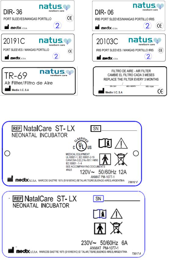
Equipment Identification
13

1. INTRODUCTION
The NATALCARE incubator is intended for use for newborn babies who require additional thermal and humidity support. NATALCARE incubators can be used in neonatal and pediatric intensive care units.
Standard features of the intensive care incubator offers large displays of skin and air temperatures with their respective preset temperatures. A graphic LCD screen allows users to select a configuration option menu and also to check the modular optional accessories (servo-humidity, servo-oxygen and weighing scale).
Two skin temperature probes can be used with twins or for the monitoring of core and peripheral temperature of a newborn for the early detection of thermal stress of the infant.
1.1Standard equipment
NATAL CARE ST LX
INTENSIVE CARE INCUBATOR
Includes:
A mobile command module with LCD (Liquid Crystal Display) graphic screen, air temperature sensor and two skin temperatures T1 and T2. Alarms, Trend Plots, Comfort Zone (CZ), Patient Identification (PID), Electronic Tilting Mechanism, Double walled dome. 4 access doors; two double walled, foldable 180º (2 intensive care and 2 auxiliary lateral doors), 5 oval ports; two on each intensive care door and one on the right auxiliary door, 1 MAX IV port on the left auxiliary door, 8 IV ports, X-ray cassette tray, two temperature probes (one reusable probe and one disposable probe). Pack of 4 air filters. User manual. Cabinet stand with 4 wheels (2 with brakes).
1.2Optional parts
CATALOGUE |
DESCRIPTION |
|
|
NCA-102 |
Oxygen servo-control module |
|
|
NCA-102C/1 |
Oxygen servo-control module without accessories. |
|
|
NCA-103B/1 |
Humidity servo control module 120VAC |
|
|
NCA-103B/2 |
Humidity servo control module 230VAC |
|
|
- |
Variable height adjustment system (lift) |
|
|
NCA-105 |
Integrated electronic weighing scale module |
|
|
14
CATALOGUE |
DESCRIPTION |
|
|
|
|
NCA-106 |
Drawer (mounted to the center) |
|
|
|
|
NCA-106/1 |
Drawer (mounted |
to the right) |
|
|
|
NCA-106/2 |
Drawer (mounted |
to the left) |
|
|
|
NCA-107 |
IV Pole |
|
|
|
|
NCA-108 |
Monitor shelf (maximum weight admitted: 25 kg) |
|
|
|
|
NCA-109 |
Additional iris port for lateral right door |
|
|
|
|
NCA-109/1 |
Additional iris port for lateral left door |
|
|
|
|
NCA-110 |
Four Antistatic wheels |
|
|
|
|
NCA-112 |
Short Pole for accessories |
|
|
|
|
NCA-113 |
Gel Mattress |
|
|
|
|
NCA-121 |
Type E Oxygen Cylinder Holder |
|
|
|
|
NCA-126 |
Flexible holder for ventilator tubing |
|
|
|
|
NCA-127 |
Water discharge tank set for NCA-103 |
|
|
|
|
NCA-128 |
Reusable water tank for NCA-103 |
|
|
|
|
NCA-131 |
Column for accesories |
|
|
|
|
NCA-132/1 |
Auxiliary outputs 120VAC |
|
|
|
|
NCA-132/2 |
Auxiliary outputs 230VAC |
|
|
|
|
NCA-137 |
Additional insert for drawer |
|
|
|
|
SMC-NC01 |
Resuscitation system |
|
|
|
|
1.3Accessories, consumables, and replacement parts
CATALOGUE |
DESCRIPTION |
|
|
TR-69 |
Air filter (4 pieces per pack) |
|
|
13142 |
Mattress (without weighing scale module) |
|
|
13147 |
Mattress (with weighing scale module) |
|
|
13156 |
Complementary mattress (with weighing scale module) |
|
|
15

23464 |
Port gasket |
|
|
DIR-06 |
Iris port sleeves (100 pieces per pack) |
|
|
DIR-10 |
Skin temperature probe (reusable) |
|
|
R25266 |
IV Ports |
|
|
R25270 |
MAX IV port |
|
|
DIR-30 |
Disposable skin temperature probe (12 pieces per pack) |
|
|
DIR-34 |
Skin temperature probe cover (120 pieces per pack) |
|
|
DIR-36 |
Oval hand port sleeves (100 pieces per pack) |
|
|
R18130 |
Servo-humidity hose set |
|
|
18136 |
Oxygen supply hose set |
|
|
R43690 |
Set of 2 Oxygen Sensors |
|
|
R18130/10 |
Package of 10 humidity hoses |
|
|
1.4Technical and functional specifications
1.4.1 Essential performance
The essential performance of an Intensive Care Infant Incubator is to keep an adequate thermal environment for newborn during long term treatment and assure isolation of the patient.
1.4.2 Technical specifications
ENVIRONMENTAL CONDITIONS RECOMMENDED FOR NORMAL FUNCTIONING TEMPERATURE: 18 - 30 ºC / 64.4 -86 ºF
BAROMETRIC PRESSURE: 86-106 Kpa (648-795mmHg) RELATIVE HUMIDITY: 50±5%
AIR SPEED: 6-8 m/min
Dimensions:
Baby’s compartment (useful area)
Width |
80 cm / 31.5 in |
Height |
40 cm / 15.7 in |
16
Depth |
48 cm / 18.9 in |
External dimensions |
|
Height |
135 cm / 53.1 in |
Width |
105 cm / 41.3 in |
Depth |
60 cm / 23.6 in |
Variable height system incubator (optional) |
|
Mattress height range + 30 cm / 11.8 in |
|
Mattress area |
|
Width |
61 cm / 24 in |
Depth |
40 cm / 15.7 in |
Access doors |
|
Front and back |
|
Width |
72 cm / 28.3 in |
Height |
32 cm / 12.6 in |
Lateral doors |
|
Width |
31 cm / 12.2 in |
Height |
32 cm / 12.6 in |
Gross weight (Basic equipment) |
78 Kg / 172 lb |
Electronic tilting mechanism |
Angle ± 15º |
Access |
|
Oval hand port, automatic and noiseless |
5 |
Iris port |
(2 optional) |
MAX IV port |
1 |
IV ports |
8 |
Lateral doors |
4 |
Oxygen enrichment capacity (volume controlled)
21% to 80% ±5%
Maximum CO2 concentration: <<0.5%( according to IEC60601-2-19, clause 105.1)
Temperature controls
Air: 20 to 37 C / 68 to 98.6 F (0.1 C/ºF) up to 39°C / 102.2 F with override key Skin 1 (T1): 34 to 37 °C / 93.2 to 98.6 F (0.1 C/ºF) up to 38°C / 100.4ºF with
override key
Indicators (Displays)
Skin temperature (T1): (control/ real temperature) Resolution: 0.1 C/ºF
Measurement range: 10 to 45 C / 50 to 113 F Accuracy: ±0.3 ºC /±0.6 ºF
Skin control temperature (T1)
Control range: 34 to 37 ºC / 93.2 to 98.6 ºF (with override up to 38 ºC /100.4 ºF)
Air temperature: (control/ real temperature) Resolution: 0.1 C/ºF
Measurement Range: 10 to 45 C / 50 to 113 F Accuracy: ±0.3 ºC /±0.6 ºF
Air control temperature
17
Control range: 20 to 37 ºC / 68 to 98.6 F (with override up to 39ºC / 102.2 F)
Graphic Screen |
LCD |
Alarms (visual and audible)
Alarm condition indicator.
Skin temperatures: ± 1°C / ± 2ºF (adjustable)
Air temperatures: + 1ºC, - 3°C / + 2ºF, - 5ºC (adjustable)
Skin / air sensor failure.
Air flow failure.
Electronic circuit failure.
Power supply failure.
Air overheating alarm with independent circuit.
Alarms test: activates all the indicators.
Alarm reset: only silences the sound alarm during 15 minutes. A new alarm condition activates it again.
Alarms are silenced during 45 minutes when the incubator is powered on, while the preset parameters are stabilized.
MODULE ALARMS: SERVO-HUMIDITY, SERVO-OXYGEN, WEIGHING SCALE
OPTIONAL MODULES
NCA-102: SERVO-OXYGEN
Measurement range: 18-100% Control range: 21-80% Accuracy: ±3%
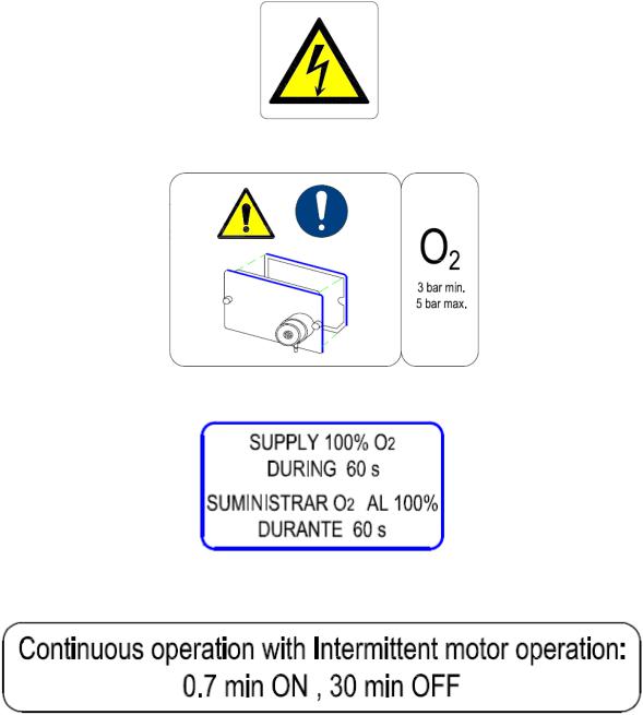
O2 Supply Pressure: 300 to 500 kPa (normal: 350kPa)
Oxygen Monitor:
Measurement basis: electrochemical cells. Oxygen sensors R-17MED.
Range: 0-100% O2 (max), 0-1% O2 (min).
Accuracy: within 1% at depth of scale with continuous temperature and pressure. Response time: <6 seconds at 90% from the final value.
Functioning Humidity: 0-99 %( non-condensing).
Functioning Temperature: 0 – 40 ºC / 32 – 104 ºF
Expected service life: 48 months on air at 25 ºC / 77 ºF and 50 RH%
NCA-103: SERVO-HUMIDITY
Measurement range: 20-100%
Control range: 40-95%
Accuracy: ±7%
NCA-105: ELECTRONIC WEIGHING SCALE
Maximum weight admitted: 8000 g / 282.19 oz
Reading steps: 1 g / 0.01 oz
Accuracy: ±5 g / ±0.18 oz
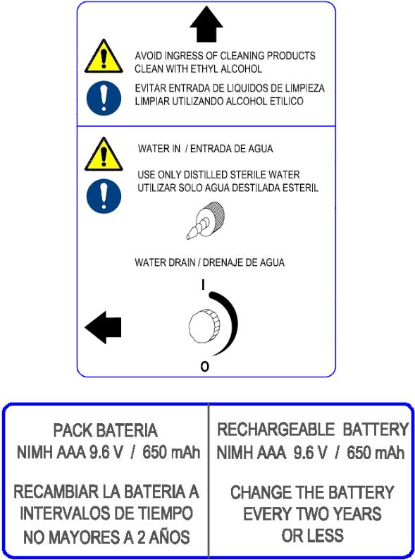
Internal Battery Pack (control module)
Powers sound alarm in case of power supply failure and for parameters recording.
18
NiMH 9,6V-650mAh
Power Supply
230 V~ 50-60 Hz
120 V~ 50-60 Hz
Interchangeable skin temperature probes ± 0.1 C/ºF.
Automatic Initialization
34 C / 93.2 F for air temperature and 36 C / 96.8 F for skin temperature. Memory for control settings and operational mode.
Packing and Storing
Medical equipment – Fragile – do not pile up
Environmental Conditions: keep in a dry place.
1.4.3 Functioning
Technical and operational specifications are referred to IEC 60601-2-19 standards:
“Particular requirements for safety of baby incubators”
1.Warm-up time: 30 minutes. Heating rate approx. 10 °C / 50 F every 30 minutes.
2.Temperature variation: ± 0.2 °C / ± 0.4ºF
3.Control temperature range:
SKIN MODE (skin control) 34.0 to 37.0 C / 93.2 to 98.6 F with override key up to 38.0 °C / 100.4 F in 0.1 ºC/ºF steps.
AIR MODE (air control) 20.0 to 37.0 C / 68 to 98.6 F with override key up to
39.0°C / 102.2 F in 0.1 ºC/ºF steps.
4.Temperature overshoot: 0.3 C / 0.6 ºF.
5.Temperature control System:
SKIN MODE: Keeps a constant baby skin temperature, according to the preset value indicated by the clinician. (SKIN TEMPERATURE CONTROL).
AIR MODE: Keeps a constant air temperature inside the incubator, according to the preset value indicated by the clinician. (AIR TEMPERATURE CONTROL).
AIR MODE / TWINS: In case of having twins inside the incubator, two skin temperature probes (T1 and T2) are used as thermometers.
AIR MODE / THERMAL MONITORING: Two skin temperature probes (T1 and T2) are used to monitor the core and peripheral difference of the same infant.
6.Correlation between the incubator temperature and the stabilized indicated temperature: < 0.3 C/0.6ºF.
19

7.Correlation between the Skin control temperature and the indicated skin temperature: < 0.1 C/0.2ºF.
8.Continuous autocalibration of the measurement electronic circuits.
9.Continuous circuit self-check.
10.Skin T1 and T2 temperature alarms activation range: ± 1 C / ± 2ºF from skin control temperature (factory default).
Skin T1 and T2 temperature alarms preset limits:
Low range: -1ºC, -0,5ºC (-2ºF,-1.5ºF, -1ºF); High range: +0,5ºC, +1ºC (+1ºF, +1.5ºF, +2ºF)
Alarm limits can be changed on CONFIGURATION screen.
11.Air temperature alarm activation range: +1 C, -3 C (+2ºF, -5ºF) from air control temperature (factory default). (After power on the unit, this alarm mutes during 45 minutes to allow the incubator reach the stabilized temperature).
Air temperature alarm preset limits.
Low range: -3ºC, -2.5ºC, -2ºC, -1.5ºC, -1ºC, -0.5ºC
(-5.0ºF, -4.5ºF, -4.0 ºF, -3.5 ºF, -3.0 ºF, -2.5 ºF, -2.0 ºF, -1.5 ºF, -1.0 ºF) High range: +3ºC, +2.5ºC, +2ºC, +1.5ºC, +1ºC, +0.5ºC
(+5.0ºF, +4.5ºF, +4.0 ºF, +3.5 ºF, +3.0 ºF, +2.5 ºF, +2.0 ºF, +1.5 ºF, +1.0 ºF)
12.Air speed range over mattress: 0.1 m/sec.
13.Air flow alarm activation time when a failure occurs: <45 seconds.
14.SKIN TEMPERATURE electronic thermometer resolution: 0.1 C/ºF
15.AIR TEMPERATURE electronic thermometer resolution: 0.1 C/ºF
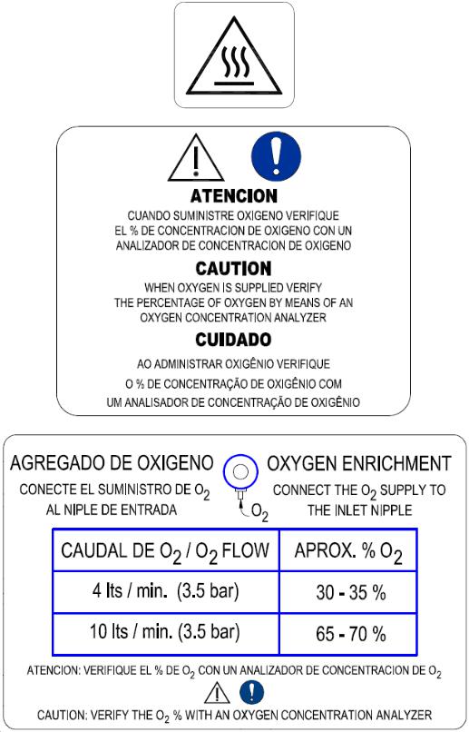
16.Oxygen concentration (flow controlled)
4 lts/min (3.5bar):30-35% O2.
10 lts/min (3.5bar): 65-70% O2.
17.Humidity:
Measurement range: 20 – 100%
Control range: 40 - 95%, ± 5% (steps of 1%).
18.CO2 maximum concentration: << 0,5%(according to IEC60601-2-19 standard, clause 105.1)
19.Maximum inner noise level in normal use conditions: < 50 dBa
20.Maximum inner noise level during alarm activation: < 80 dBa
20
21.Maximum noise level at 3 meters from the incubator during alarm activation: > 65 dBa
22.Maximum weight suggested for shelves and trays: 25 Kg / 55 lb.
23.Air filter: Filters particles bigger than 0.3 microns.
24.Oxygen filter: Filters particles bigger then 0.5 microns.
 WARNING! Read the Operational Check Procedure, section 5.13 of this manual, before operating the incubator. If a problem is detected during any stage of the Functional Check Procedure the incubator should not be used. Contact the Authorized Service Center.
1.5Access
Four intensive care doors foldable 180º with double locking mechanism
Five automatic hand ports
MAX IV port
Eight IV ports
1.5.1 Access through automatic hand ports
The hood has five automatic hand ports used for routine procedures with the infant. To avoid your hand contamination open the hand ports pressing the latch with your elbow.
21

 CAUTION The hand port must be opened just by pushing the port latch (PUSH) as shown in the picture below to prevent breakages.
Figure 1: Automatic hand ports
 WARNING! Use hand port sleeves and iris sleeves while the incubator is functioning to protect the infant’s thermal environment.
 WARNING! Do not move the incubator while a patient is under treatment.
22

1.6Double wall
The double wall is incorporated in the front and back intensive care doors.
Open the double wall by moving the inner door to the right, releasing it from the door retaining pins.
 CAUTION Once cleaning is finished, place the double wall in its place again.
PLACING THE OVAL HAND PORT
SLEEVES
Unlatch the double wall to place the oval hand port sleeves.
1.7Double Dome
The double dome is removed by first gently pressing from one end towards the center of the incubator for it to unlock.
 CAUTION Once cleaning is finished, place the double dome in its place again and make sure it is positioned correctly.
23

1.8X-ray cassette tray
The x-ray cassette is fully integrated to the mattress holder base. To access the tray open the front door and gently slide the tray out.
1.9Command module positioning
Manual knob A enables to modify the vertical position of the command module to give the user a better view angle. Adjust the knob to fix the position.
Manual knob B enables to rotate the command module to the laterals.
A
B
24

2. UNPACKING AND ASSEMBLY
2.1Assembly instructions
When unpacking the equipment, check that all parts are in good condition. Otherwise, contact your supplier or sales dealer to report any problems immediately.
The command module is packed separately. When taking the equipment out of the boxes, be careful not to damage the surfaces. Place the module on the support and connect the communication cable to the back as shown in the pictures:
Clean the equipment according to the instructions described in section 7 of the reference manual.
Connect the power supply cable and the temperature probes according to the instructions described in section 4 of the reference manual.
Once the equipment is unpacked it must be plugged in at least 16 hours to ensure the charge of the internal batteries.
 WARNING! The power supply cable must be connected to a medical grade power outlet with a grounded connection. Do not use adapter plugs or extension cables.
The room temperature where the equipment will function must be between 18ºC and 30ºC (64.4 and 86ºF).
25

 WARNING! This equipment is not suitable for use in the presence of flammable anesthetics. An explosion hazard exists under these conditions.
 WARNING! Remove all the packing material, including the mattress protecting plastic cover before using the incubator on patients.
 WARNING! To avoid the equipment slipping when it is on a slope, the front wheels of the rolling base must face to the slope and set the brakes, as shown in the picture.
WARNING! Medical electrical equipment needs special precautions regarding EMC and needs to be installed and put into service according to EMC information provided in user and technical service manuals
 WARNING! Do not place auxiliary equipment producing sparks in the incubator.
2.2Starting up – software versions
Connect the equipment to 230V~ (120V~) grounded socket.
Check that the thermal breaker (located at the bottom and lateral part of the support) is on.
26
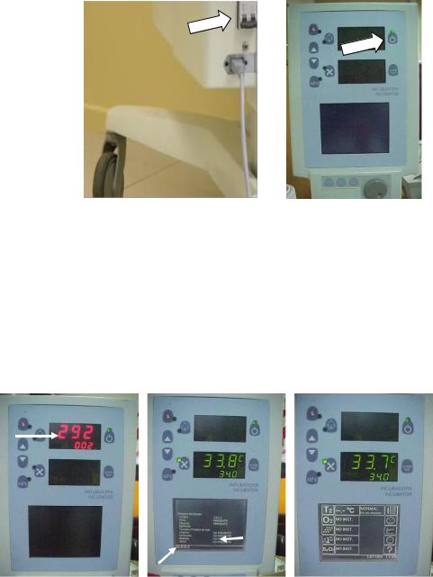
The green led shall light up and a “beep” sounds when the control module receives power supply.
Press  for approximately 2 seconds.
Upper digital displays will light up and the control software version is immediately indicated at the top part. Then a self-check routine runs automatically showing on the screen the optional modules incorporated and their current software versions. On the lower part of the screen it is shown the software version of the respective screen.
1
3
2
1.CONTROL SOFTWARE VERSION
2.SCREEN SOFTWARE VERSION
3.OPTIONAL MODULES SOFTWARE VERSIONS
The incubator is functioning in AIR MODE with a preset control temperature at 34 ºC.
27

2.3Electromagnetic Compatibility Comments
Guidance and manufacturer’s declaration – electromagnetic emissions
The NATAL CARE ST is intended for use in the electromagnetic environment specified below. The customer or the user of the NATAL CARE ST should assure that it is used in such an environment
Emissions test |
Compliance |
Electromagnetic environment - guidance |
|
|
|
The NATAL CARE ST uses RF energy only for its |
|
RF emissions |
Group 1 |
internal function. Therefore, its RF emissions are |
|
CISPR 11 |
very low and are not likely to cause any interference |
||
|
|||
|
|
in nearby electronic equipment |
|
RF emissions |
Class A |
|
|
CISPR 11 |
The NATAL CARE is suitable for use in all |
||
|
|||
Harmonic emissions |
Class A |
establishments other than domestic and those |
|
IEC 61000-3-2 |
directly connected to the public low-voltage power |
||
|
|||
Voltage fluctuations / |
|
supply network that supplies buildings used for |
|
flicker emissions |
Complies |
domestic purposes. |
|
IEC 61000-3-3 |
|
|
|
|
|
Table 201 (IEC 60601-1-2:2004) |
Guidance and manufacturer’s declaration – electromagnetic immunity
The NATAL CARE ST is intended for the use in the electromagnetic environment specified below. The customer or the user of the NATAL CARE ST should assure that it is used in such an environment
Immunity test |
IEC 60601 |
Compliance |
Electromagnetic environment - |
|
test level |
level |
guidance |
||
|
||||
|
|
|
Floors should be wood, concrete |
|
Electrostatic |
+/- 6kV contact |
+/- 6kV contact |
or ceramit tile. If floors are |
|
discharge (ESD) |
covered with synthetic material, |
|||
+/- 8 kV air |
+/- 8 kV air |
|||
IEC 61000-4-2 |
the relative humidity should be at |
|||
|
|
|||
|
|
|
least 30% |
|
|
|
+/- 2kV for |
|
|
|
+/- 2kV for power supply |
power supply |
|
|
Electrical fast |
lines |
lines |
Mains power quality should be |
|
transient/burst |
|
|
that of a typical commercial or |
|
IEC 61000-4-4 |
+/- 1 kV for input/output |
+/- 1 kV for |
hospital environment |
|
|
lines |
input/output |
|
|
|
|
lines |
|
|
|
|
+/- 1kV line(s) to |
|
|
Surge |
+/- 1kV line(s) to line(s) |
line(s) |
Mains power quality should be |
|
|
|
that of a typical commercial or |
||
IEC 61000-4-5 |
|
|
||
+/- 2kV line(s) to earth |
+/- 2kV line(s) to |
hospital environment. |
||
|
||||
|
|
earth |
|
|
Voltage dips, short |
< 5% UT |
< 5% UT |
Mains power quality should b that |
|
(>95% dip in UT) |
(>95% dip in UT) |
of a typical commercial or |
||
interruptions and |
||||
for 0,5 cycle |
for 0,5 cycle |
hospital environment. If the user |
||
voltage variations |
||||
|
|
of the NATAL CARE ST requires |
||
on power supply |
|
|
||
40% UT |
40% UT |
continued operation during power |
||
input lines |
||||
(60% dip in UT) |
(60% dip in UT) |
mains interruptions, it is |
||
IEC 61000-4-11 |
||||
for 5 cycles |
for 5 cycles |
recommended that the NATAL |
||
|
28
|
|
|
CARE ST be powered from an |
|
|
70% UT |
70% UT |
uninterruptible power supply or a |
|
|
(30% dip in UT) |
(30% dip in UT) |
battery. |
|
|
for 25 cycles |
for 25 cycles |
|
|
|
<5% UT |
<5% UT |
|
|
|
(>95% dip in UT) |
(>95% dip in UT) |
|
|
|
for 5 sec |
for 5 sec |
|
|
Power frequency |
|
|
Power frequency magnetic fields |
|
|
|
should be at levels characteristic |
||
(50/60Hz) |
|
|
||
3 A/m |
3 A/m |
of a typical location in a typical |
||
magnetic field |
||||
|
|
commercial or hospital |
||
IEC 61000-4-8 |
|
|
||
|
|
environment |
||
|
|
|
||
NOTE UT is the a.c. mains voltage prior to application of the test level |
||||
|
|
|
Table 202 (IEC 60601-1-2:2004) |
|
29

Guidance and manufacturer´s declaration – electromagnetic immunity
The NATAL CARE ST is intended for the use in the electromagnetic environment specified below. The customer or the user of the NATAL CARE ST should assure that it is used in such an environment
Immunity test |
IEC 60601 test level |
Compliance |
Electromagnetic environment - guidance |
|
level |
||||
|
|
|
||
|
|
|
Portable and mobile RF communications |
|
|
|
|
equipment should be used no clorser to any |
|
|
|
|
part of the NATAL CARE ST, including |
|
|
|
|
cables, that the recommended separation |
|
|
|
|
distance calculated from the equuation |
|
|
|
|
aplicable to the freuency of the transmitter |
|
|
|
Recommended separation distance |
|
|
|
d = 1,2√P |
Conducted RF |
3 Vrms |
3 Vrms |
|
IEC 61000-4-6 |
150 kHz to 80 MHz |
|
|
|
|
|
d = 1,2 √P 80 MHz to 800 MHz |
Radiated RF |
3 V/m |
3 V/m |
d = 2,3 √P 800 MHz to 2,5 GHz |
IEC 61000-4-3 |
80 MHz to 2,5 GHz |
|
|
|
|
|
where P is the maximum output power rating |
|
|
|
of the transmitter in watts (W) according to |
|
|
|
the transmitter manufacturer and d is the |
|
|
|
recommended separation distance in meters |
|
|
|
(m). |
|
|
|
Field strengths from fixed RF transmitters, |
|
|
|
as determined by an electromagnetic site |
|
|
|
survey, a should be less than the compliance |
|
|
|
level in each frequency range. b |
|
|
|
Interference may occur in the vicinity of |
|
|
|
equipment marked with the following symbol: |
NOTE 1 At 80 MHz and 800 MHz, the higher frequency range applies.
NOTE 2 These guidelines may not apply in all situations. Electromagnetic propagation is affected by absorption and reflection from structures, objects and people.
aField strengths from fixed transmitters, such as base stations fro radio (cellular/cordless) telephones and land mobile radios, amateur radio, AM and FM radio broadcast and TV broadcast cannot be predicted theoretically with accuracy. To assess the electromagnetic environment due to fixed RF transmitters, an electromagnetic site survey should be considered. If the measured field strength in the location in which the NATAL CARE ST is used exceeds the applicable RF compliance level above, the NATAL CARE ST should be observed to verify normal operation. If abnormal performance is observed, additional measures may be necessary, such as reorienting or relocating the NATAL CARE ST.
bOver the frequency range 150 kHz to 80 MHz, field strengths should be less than 3 V/m
Table 204 (IEC 60601-1-2:2004)
30
 Loading...