

natus OLYMPIC STERILE-DRIER 43, OLYMPIC STERILE-DRIER 44 Instruction Manual
Instruction Manual
CAUTION
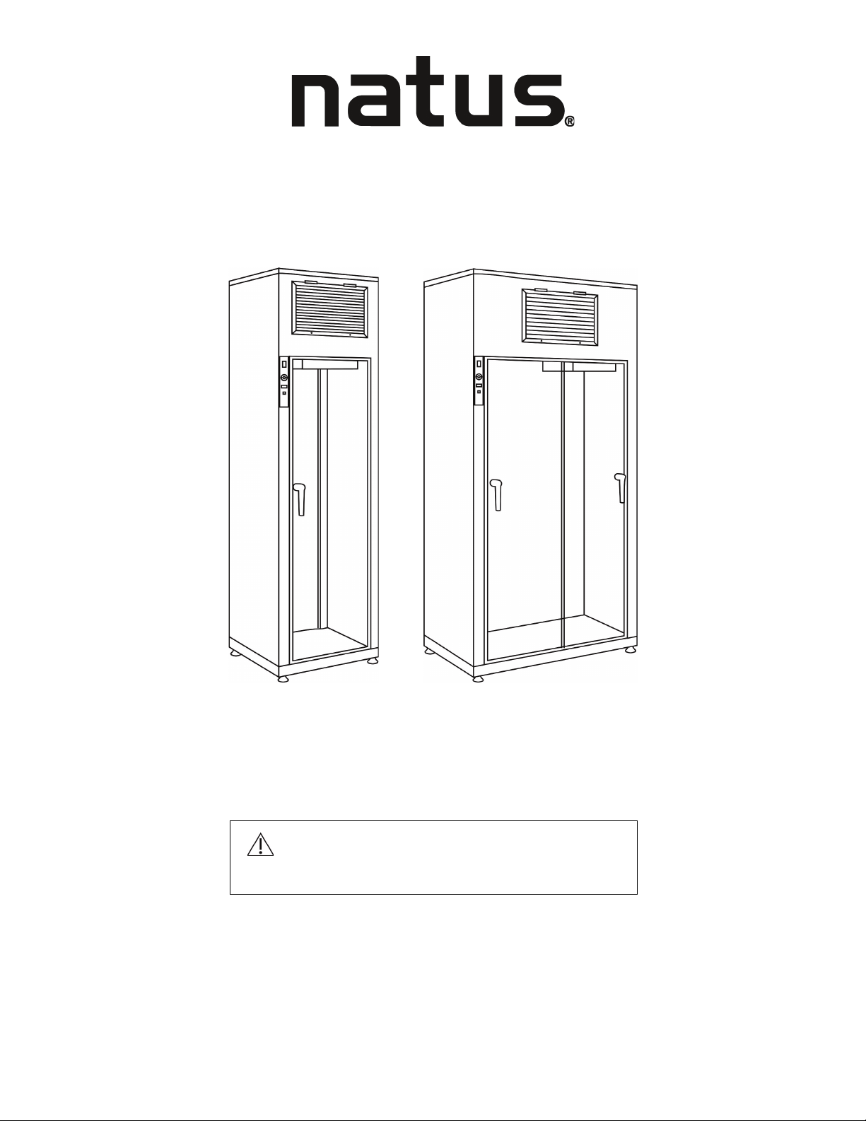
OLYMPIC STERILE-DRIER
Model 43/44
Read and be familiar with this manual before installing,
operating, or servicing this device. To ensure operator,
technician, and patient safety, use only as specified in
this manual.
TM
602018C


Product Manufacturer:
Natus Medical Incorporated
5900 First Avenue South
Seattle, WA 98108 USA
Global sales & support: 1-800-303-0306
Phone: +1-206-767-3500
Fax: +1-206-762-4200
Web: www.natus.com
European Union Authorized Representative
Natus Europe GmbH
Robert-Koch-Str. 1
82152 Planegg, Germany
The information in this manual is subject to change without notice.
No part of this manual may be photocopied, reproduced, translated, or reduced to any electronic medium
without the express written permission of Natus
Medical Incorporated.
All tradenames and trademarks mentioned herein are property of their respective owners.
Copyright © 2012 Natus Medical Incorporated. All rights reserved.


Contents
Section 1 Overview . . . . . . . . . . . . . . . . . . . . . . . . . . . . . . . . . . . . . . 1-1
Section 2 Installation. . . . . . . . . . . . . . . . . . . . . . . . . . . . . . . . . . . . . 2-1
Conventions . . . . . . . . . . . . . . . . . . . . . . . . . . . . . . . . . . . . . . . . . . . . . . . 1-1
Symbols . . . . . . . . . . . . . . . . . . . . . . . . . . . . . . . . . . . . . . . . . . . . . . . . . . 1-1
Intended Use . . . . . . . . . . . . . . . . . . . . . . . . . . . . . . . . . . . . . . . . . . . . . . 1-2
Description. . . . . . . . . . . . . . . . . . . . . . . . . . . . . . . . . . . . . . . . . . . . . . . . 1-2
Accessories . . . . . . . . . . . . . . . . . . . . . . . . . . . . . . . . . . . . . . . . . . . . . . . 1-3
Installing the Drier. . . . . . . . . . . . . . . . . . . . . . . . . . . . . . . . . . . . . . . . . . 2-1
Space Requirements . . . . . . . . . . . . . . . . . . . . . . . . . . . . . . . . . . . . . . 2-1
Sterile-Drier Model 43 . . . . . . . . . . . . . . . . . . . . . . . . . . . . . . . . . 2-1
Sterile-Drier Model 44 . . . . . . . . . . . . . . . . . . . . . . . . . . . . . . . . . 2-1
Electrical Requirements . . . . . . . . . . . . . . . . . . . . . . . . . . . . . . . . . . . 2-2
Assembly . . . . . . . . . . . . . . . . . . . . . . . . . . . . . . . . . . . . . . . . . . . . . . . . . 2-2
Installing the Floor Anchors. . . . . . . . . . . . . . . . . . . . . . . . . . . . . . . . 2-3
Venting . . . . . . . . . . . . . . . . . . . . . . . . . . . . . . . . . . . . . . . . . . . . . . . . 2-4
Inspecting the Heaters . . . . . . . . . . . . . . . . . . . . . . . . . . . . . . . . . . . . . . . 2-4
Testing the Drier . . . . . . . . . . . . . . . . . . . . . . . . . . . . . . . . . . . . . . . . . . . 2-6
Section 3 Operation. . . . . . . . . . . . . . . . . . . . . . . . . . . . . . . . . . . . . . 3-1
Operating the Drier . . . . . . . . . . . . . . . . . . . . . . . . . . . . . . . . . . . . . . . . . 3-1
Loading Parts and Tubes . . . . . . . . . . . . . . . . . . . . . . . . . . . . . . . . . . 3-1
Drying Parts . . . . . . . . . . . . . . . . . . . . . . . . . . . . . . . . . . . . . . . . . . . . 3-1
Drying Tubes . . . . . . . . . . . . . . . . . . . . . . . . . . . . . . . . . . . . . . . . . . . 3-2
Controls and Signals. . . . . . . . . . . . . . . . . . . . . . . . . . . . . . . . . . . . . . 3-2
Main Power Switch . . . . . . . . . . . . . . . . . . . . . . . . . . . . . . . . . . . . 3-3
Temperature Control . . . . . . . . . . . . . . . . . . . . . . . . . . . . . . . . . . . 3-3
Timer Control . . . . . . . . . . . . . . . . . . . . . . . . . . . . . . . . . . . . . . . . 3-3
Section 4 Maintenance . . . . . . . . . . . . . . . . . . . . . . . . . . . . . . . . . . . 4-1
Weekly Maintenance . . . . . . . . . . . . . . . . . . . . . . . . . . . . . . . . . . . . . . . . 4-1
Cleaning the Drier . . . . . . . . . . . . . . . . . . . . . . . . . . . . . . . . . . . . . . . 4-1
Periodic Maintenance . . . . . . . . . . . . . . . . . . . . . . . . . . . . . . . . . . . . . . . 4-2
Changing the Prefilter . . . . . . . . . . . . . . . . . . . . . . . . . . . . . . . . . . . . 4-2
Semi-Annual Maintenance . . . . . . . . . . . . . . . . . . . . . . . . . . . . . . . . . . . 4-2
Lubricating the Blowers . . . . . . . . . . . . . . . . . . . . . . . . . . . . . . . . . . . 4-2
Every Three Years . . . . . . . . . . . . . . . . . . . . . . . . . . . . . . . . . . . . . . . . . . 4-5
Replacing the HEPA Filter. . . . . . . . . . . . . . . . . . . . . . . . . . . . . . . . . 4-5
OLYMPIC STERILE-DRIER Model 43/44 Instruction Manual v

Section 5 Troubleshooting . . . . . . . . . . . . . . . . . . . . . . . . . . . . . . . . 5-1
Technical Support. . . . . . . . . . . . . . . . . . . . . . . . . . . . . . . . . . . . . . . . . . .5-2
Section 6 Service . . . . . . . . . . . . . . . . . . . . . . . . . . . . . . . . . . . . . . . . 6-1
Repair Policy . . . . . . . . . . . . . . . . . . . . . . . . . . . . . . . . . . . . . . . . . . . . . .6-1
Repair Procedures. . . . . . . . . . . . . . . . . . . . . . . . . . . . . . . . . . . . . . . . . . .6-1
Replacing the Main and Transformer Fuses . . . . . . . . . . . . . . . . . . . .6-2
Replacing the Heater . . . . . . . . . . . . . . . . . . . . . . . . . . . . . . . . . . . . . .6-3
Replacing the Control Panel Printed Circuit Board . . . . . . . . . . . . . .6-4
Replacing the Thermal Probe . . . . . . . . . . . . . . . . . . . . . . . . . . . . . . .6-6
Replacing the Heater Control Relay K2 . . . . . . . . . . . . . . . . . . . . . . .6-8
Replacing the Blower Control Relay
(Model 44 only). . . . . . . . . . . . . . . . . . . . . . . . . . . . . . . . . . . . . . . . .6-10
Replacing the Blower/Blower Motor . . . . . . . . . . . . . . . . . . . . . . . .6-11
Testing the Thermal Cut-Out Function . . . . . . . . . . . . . . . . . . . . . . .6-14
Replacing the Thermal Cut-out . . . . . . . . . . . . . . . . . . . . . . . . . . . . .6-15
Section 7 Replacement Parts . . . . . . . . . . . . . . . . . . . . . . . . . . . . . . 7-1
Ordering Information . . . . . . . . . . . . . . . . . . . . . . . . . . . . . . . . . . . . . . . .7-1
Parts and Accessories . . . . . . . . . . . . . . . . . . . . . . . . . . . . . . . . . . . . .7-1
Section 8 Specifications . . . . . . . . . . . . . . . . . . . . . . . . . . . . . . . . . . 8-1
Appendix A Drawings and Schematics . . . . . . . . . . . . . . . . . . . . . . . . A-1
vi OLYMPIC STERILE-DRIER Model 43/44 Instruction Manual
Overview
NOTE
#
CAUTION
WARNING
Section
1
Conventions
This manual provides the necessary information to install, maintain, and service the
Olympic Sterile-Drier
this manual are intended for use by qualified service technicians.
The following conventions are used in this manual.
Table 1.1
Convention Description
BUTTON
Conventions
Notes provide additional information to clarify a point in the text.
Cautions indicate situations that, if not avoided, could result in minor
to
Warnings indicate situations that, if not avoided, could result in
serious
This character style represents buttons and controls that the user
can
TM
Model 43/44. The installation and service instructions in
moderate injury to the patient or operator, or damage to the equipment.
injury or death to the patient or operator.
touch or press.
Symbols
The following symbols are located on the Olympic Driers and their packaging.
Table 1.2
Symbol Description Symbol Description
OLYMPIC STERILE-DRIER Model 43/44 Instruction Manual 1-1
Symbols
Caution, hot surfaces Mains power ON
Caution, read instructions Neutral (neutral conductor)
Line (hot conductor) Protective earth (ground)
Mains power OFF Legal manufacturer
Intended Use
CAUTION
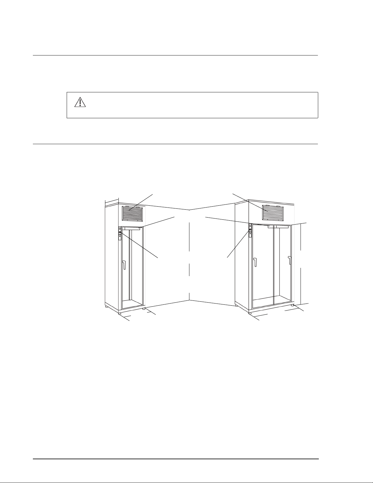
Sterile-Drier Model 43
Sterile-Drier Model 44
20.5 in.
52 cm
Prefilter access panel hinges up and out
The power cord is located
on the back of the device;
rear clearance required.
Thermostat and timer controls
86 in.
218 cm
63 in.
160 cm
Tube holder
46.5 in
117 cm
26 in.
66 cm
Intended Use
Olympic Driers are intended to rapidly dry pasteurized medical equipment,
primarily respiratory therapy and anesthesia parts. The Drier should be used after
disinfection by pasteurization or liquid chemical means.
Sterile-Driers are not intended for storing or warming solutions.
Description
Sterile-Driers use HEPA filtered, heated air to dry parts. The additional filtering
reduces the risk of contamination.
Figure 1.1
Sterile-Drier
1-2 OLYMPIC STERILE-DRIER Model 43/44 Instruction Manual

Accessories
Accessories
Natus Medical offers the following items that are compatible for use with the
Sterile-Drier. To order these items, see
Tube Holder: Slide out tube holder is capable of holding 35 1-in.
diameter
Standard Bag Drier: Adapter fits in any Sterile-Drier that holds 16 breathing
tubes.
page 7-1.
bags. Fits in the tube holder position in the Drier.
Drying arms, narrow: Small diameter arms for use with narrow necked
breathing bags. Replaces one of the 16 standard arms.
Vent adapter: Allows Drier exhaust to connect to outside venting system.
Optional rear doors: Model 44 may be ordered for delivery built with optional
rear doors.
OLYMPIC STERILE-DRIER Model 43/44 Instruction Manual 1-3

Accessories
1-4 OLYMPIC STERILE-DRIER Model 43/44 Instruction Manual

Installation
CAUTION
Only qualified technicians should install this device.
Read and be familiar with this instruction manual before installing this device.
Installing the Drier
Space Requirements
Sterile-Drier Model 43
Section
2
Dimensions: 26-in. wide x 20.5-in. deep x 86-in. high
(66-cm wide x 52-cm deep x 218-cm high)
Rear clearance: 2-in.; 5-in. with optional vent adapter
(5-cm; 13-cm with optional vent adapter)
Weight: 125 lb (56.8 kg)
Sterile-Drier Model 44
Dimensions: 46.5-in. wide x 20.5-in. deep x 86-in. high
(117-cm wide x 52-cm deep x 218-cm high)
Rear clearance: 2-in.; 5-in. with optional vent adapter
(5-cm; 13-cm with optional vent adapter)
Weight: 247.5 lb (112.3 kg)
OLYMPIC STERILE-DRIER Model 43/44 Instruction Manual 2-1
Assembly
CAUTION
NOTE
#
CAUTION
CAUTION
Electrical Requirements
The Olympic Sterile-Drier Model 43 is available in the following configurations:
120V~, 60 Hz, 8A (standard configuration for the United States and Canada)
100V~, 50 Hz, 9.5A
100V~, 60 Hz, 9.5A
220-230V~, 50 Hz, 4.5A
220-230V~, 60 Hz, 4.5A
The Olympic Sterile-Drier Model 44 is available in the following configurations:
120V~, 60 Hz, 16A (standard configuration for the United States and Canada)
100V~, 50 Hz, 18A
100V~, 60 Hz, 18A
220-230V~, 50 Hz, 9A
220-230V~, 60 Hz, 9A
Assembly
This device must be connected directly to a properly grounded hospital-grade
electrical outlet.
Due to amperage draw, Model 44 requires a dedicated over-current protection device.
Supply voltage fluctuations are not to exceed 10% of the nominal supply voltage.
Only qualified technicians should assemble the device.
To assemble the Drier:
1 After uncrating, install the leveling feet, then carefully stand the drier upright.
2 Clean the metal surfaces with soap and water or liquid disinfectant. Clean the
plastic doors with soap and water.
Never use alcohol to clean the doors, as alcohol will damage the Plexiglas®.
3 After the Drier is in place, adjust the leveling feet (see Figure 2.1).
2-2 OLYMPIC STERILE-DRIER Model 43/44 Instruction Manual
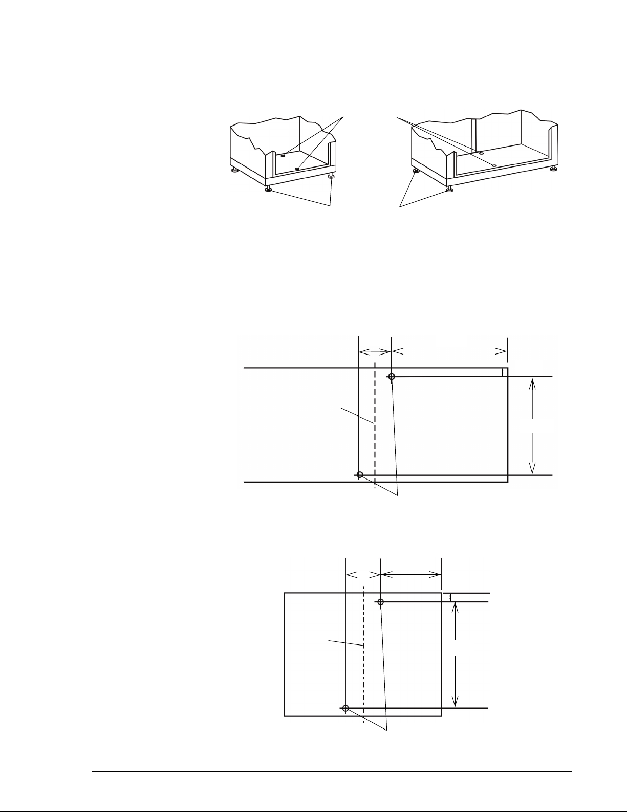
Assembly
Anchor holes
Leveling feet (x4)
Model 44
Model 43
Center line
6.0 in.
15.2 cm
20.2 in.
51.3 cm
1.45 in.
3.7 cm
17.50 in.
44.5 cm
Anchor holes
Anchor holes
Center line
17.50 in.
44.5 cm
1.45 in.
3.7 cm
9.92 in.
25.2 cm
6.0 in.
15.2 cm
Figure 2.1
Anchor holes in the Driers
Installing the Floor Anchors
The Drier must be anchored to the floor. All Driers have two anchor holes drilled
into the base plate to anchor the Drier (see Figure 2.1).
Figure 2.2
Anchor holes in the floor, Model 44
Figure 2.3
OLYMPIC STERILE-DRIER Model 43/44 Instruction Manual 2-3
Anchor holes in Model 43
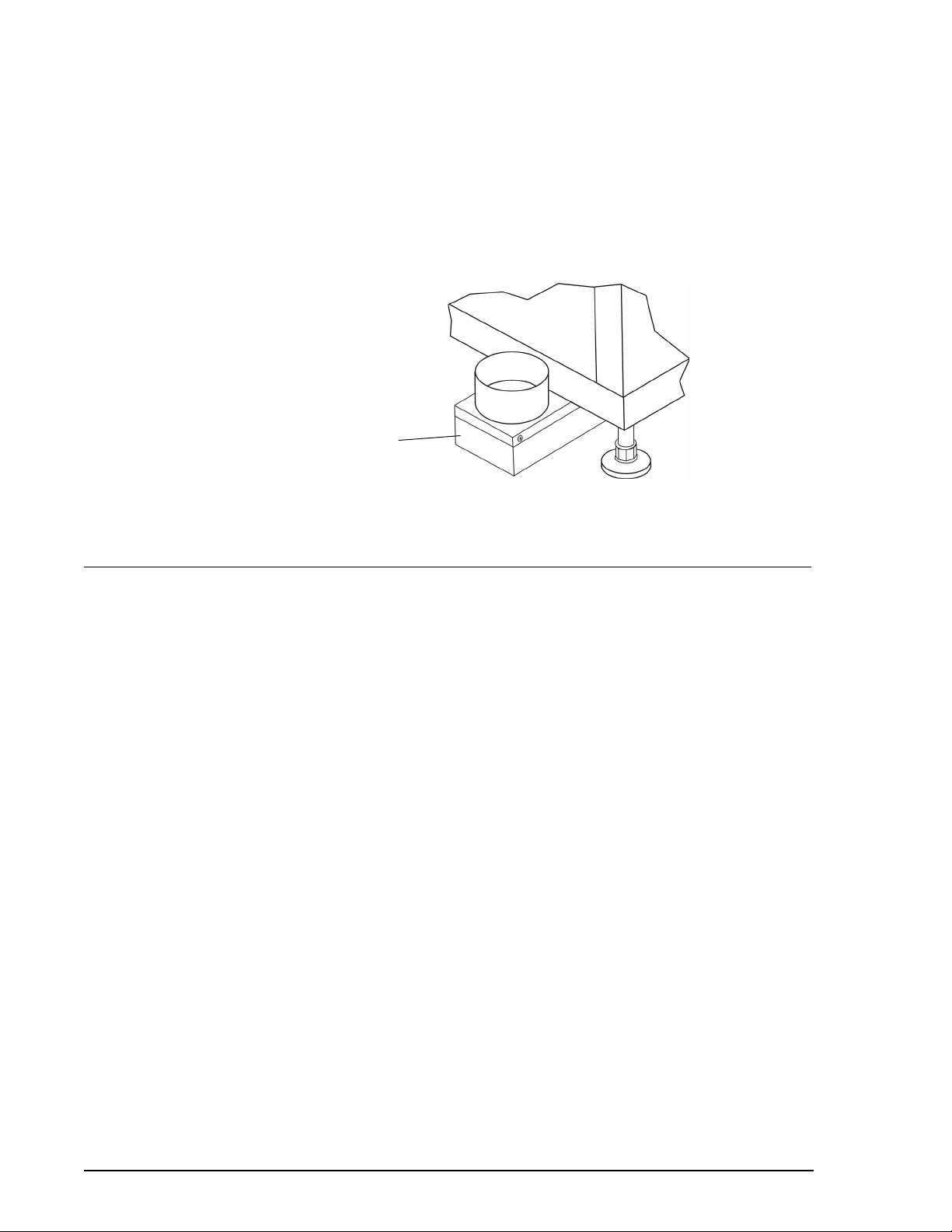
Inspecting the Heaters
Optional vent adapter
(back or side)
NOTE
#
Venting
Standard Driers vent to room air and no special venting is required. If special
venting is desired, a vent adapter is available as an option (see Figure 2.4).
The vent requires a four-inch (10-cm) hose. Connect the hose to the vent adapter
using a standard hose clamp, then connect the opposite end of the hose to a hospital
exhaust vent at normal atmospheric pressure.
Figure 2.4
Optional vent adapter
Inspecting the Heaters
If a sterile drier fails to heat, a heater might have come loose during shipping.
Model 43 Driers have two heaters; Model 44 Driers have four heaters.
If removing the heaters, ensure that the proper voltage and wattage heater is replaced into
the correct socket. For example, place the 500-watt heater in the Model 44 120V~ Drier in
the right plenum nearest the blower; the three 400-watt heaters fill the remaining sockets.
2-4 OLYMPIC STERILE-DRIER Model 43/44 Instruction Manual
For proper operation and correct locations, see the wiring diagrams appropriate for the
device’s electrical configuration (see Appendix A).
Required Items:
Heater (part no. 401572)
1.4-in. Nut Driver
To check the heater:
1 Press the power switch to the
OFF
(O) position, and then unplug the power
cord.
2 Remove the upper white door seal and loosen—but do not remove—the screws
just inside the Drier door, behind the door stop (see
Figure 2.5).
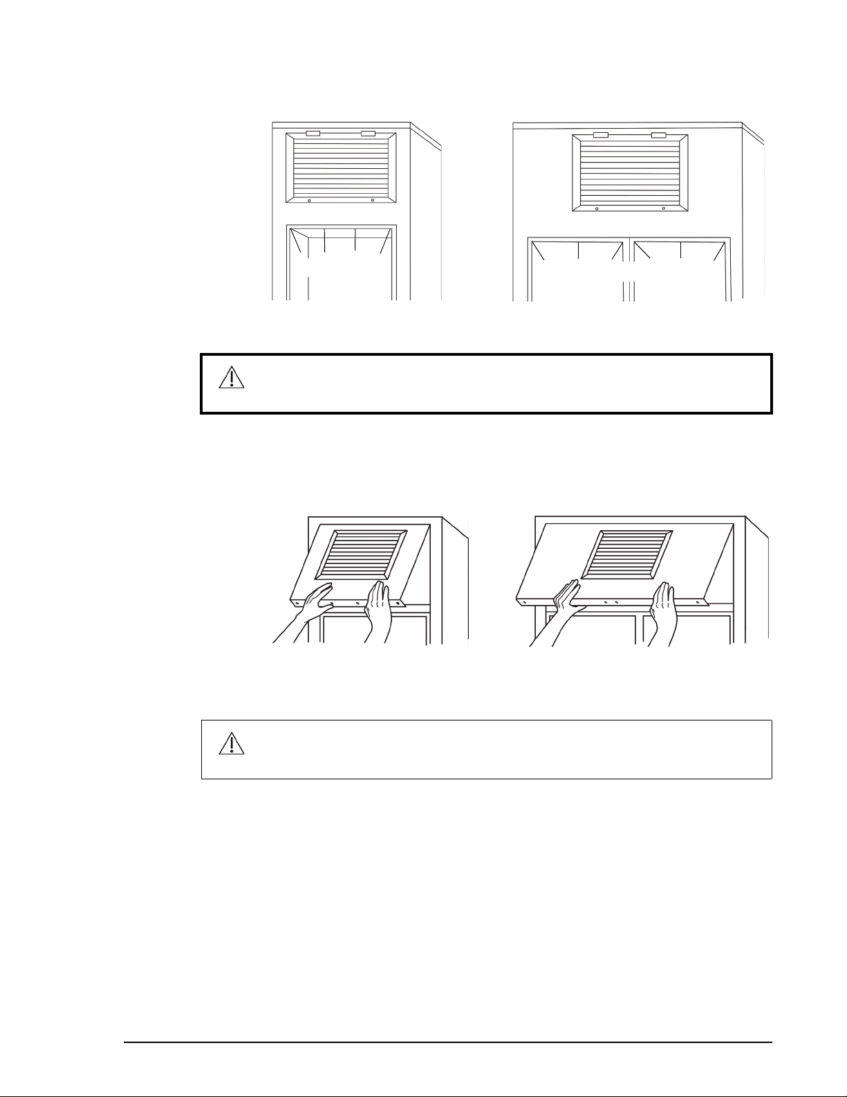
Inspecting the Heaters
Screw locations (x4)
Screw locations (x6)
WARNING
NOTE
#
CAUTION
Figure 2.5
Location of screws
3 Pull out and remove the front cover (Figure 2.6).
Electrical shock hazard when the front panel is removed.
In Model 44, the left and right plenum assemblies are mirror images of one another. For
example, the thermal cut-out on the right plenum assembly is located on the back, while
that on the left is visible from the front.
Figure 2.6
Removing the front cover
4 Unhook, remove, and set aside the plenum hold-down springs, and then
disconnect the thermal cut-out wires (see
Take care to not damage the HEPA filter. Any hole or tear adversely affects the filter
function.
OLYMPIC STERILE-DRIER Model 43/44 Instruction Manual 2-5
Figure 2.7).

Testing the Drier
HEPA filter
FRONT
Acorn nuts and washers
Blower
Blower bracket
Blower filter plate
Plenum assembly
Note: Pull together the two springs to
unlatch them, and then separate. Lift
the metal box up to access the heaters.
Figure 2.7
Accessing the blower assembly
Testing the Drier
5 Separate the plenum from the casing (or HEPA filter), and then lift the plenum
and unscrew the heater from the socket. Ensure that the socket cap is tight, and
then screw the heater firmly back into place.
6 Replace the plenum; ensure that the plenum and filter are fully seated. Install
the plenum hold-down springs, and then reconnect the thermal cut-out wires.
7 Position the front cover, tighten the screws, and then push the white door seal
place.
into
8 Plug in the power cord, and press the power switch to the
9 Test for proper operation (see Testing the Drier).
Perform the test procedure to ensure the Drier is working properly after performing
ON
(|) position.
assembly and service procedures.
To test the Drier:
1 Plug in the power cord, and press the power switch to the
ON
(|) position.
2 Set the heat control to midway between high and low, then set the timer to
3 Ensure that the blowers are operating—warm air should blow from the screened
panel above the tube holder assembly inside the drying cabinet.
2-6 OLYMPIC STERILE-DRIER Model 43/44 Instruction Manual
ON
.

Testing the Drier
NOTE
#
4 Turn the power switch to the
5 Set the timer to 30 minutes by pressing
OFF
(O) position.
SET
. Observe for 60 seconds, verifying
that the timer counts down the remaining minutes.
If the device does not operate as expected, see Troubleshooting on page 5-1.
OLYMPIC STERILE-DRIER Model 43/44 Instruction Manual 2-7

Testing the Drier
2-8 OLYMPIC STERILE-DRIER Model 43/44 Instruction Manual
Operation
WARNING
CAUTION
NOTE
#
NOTE
#
Explosion hazard. Do not use this device in the presence of flammables (e.g., oxygen,
nitrous oxide, anesthetics).
Read and be familiar with this instruction manual before using this device.
Connect this device directly to a properly grounded hospital-grade outlet.
Inner metal surfaces are hot when the Drier is on.
The hospital/facility is responsible for ensuring that all personnel who operate or maintain
this device are trained in its operation and safe use, and for maintaining training records of
attendance and evidence of understanding.
Section
3
Operating the Drier
Loading Parts and Tubes
Olympic Driers can dry combinations of parts and tubes. Removable tube holders
and parts trays can be adjusted to suit varying load requirements.
Drying Parts
To dry parts:
1 To speed drying, shake excess water from the parts before placing them on
tray.
the
2 Place the parts onto the trays, then place the trays into the Drier.
Trays can be added or removed to suit load requirements by sliding in or out.
Trays can be added to both sides of the drier for loads consisting of all parts.
OLYMPIC STERILE-DRIER Model 43/44 Instruction Manual 3-1
 Loading...