


LMH6732
High Speed Op Amp with Adjustable Bandwidth
LMH6732 High Speed Op Amp with Adjustable Bandwidth
March 2004
General Description
The LMH6732 is a high speed op amp with a unique combination of high performance, low power consumption, and
flexibility of application. The supply current is adjustable,
over a continuous range of more than 10 to 1, with a single
resistor, R
wide variety of high performance applications including device turn on/ turn off (Enable/ Disable) for power saving or
multiplexing. Typical performance at any supply current is
exceptional. The LMH6732’s design has been optimized so
that the output is well behaved, eliminating spurious outputs
on "Enable".
The LMH6732’s combination of high performance, low
power consumption, and large signal performance makes it
ideal for a wide variety of remote site equipment applications
such as battery powered test instrumentation and communications gear. Other applications include video switching matrices, ATE and phased array radar systems.
The LMH6732 is available in the SOIC and SOT23-6 packages. To reduce design times and assist in board layout, the
LMH6732 is supported by an evaluation board.
. This feature allows the device to be used in a
P
Features
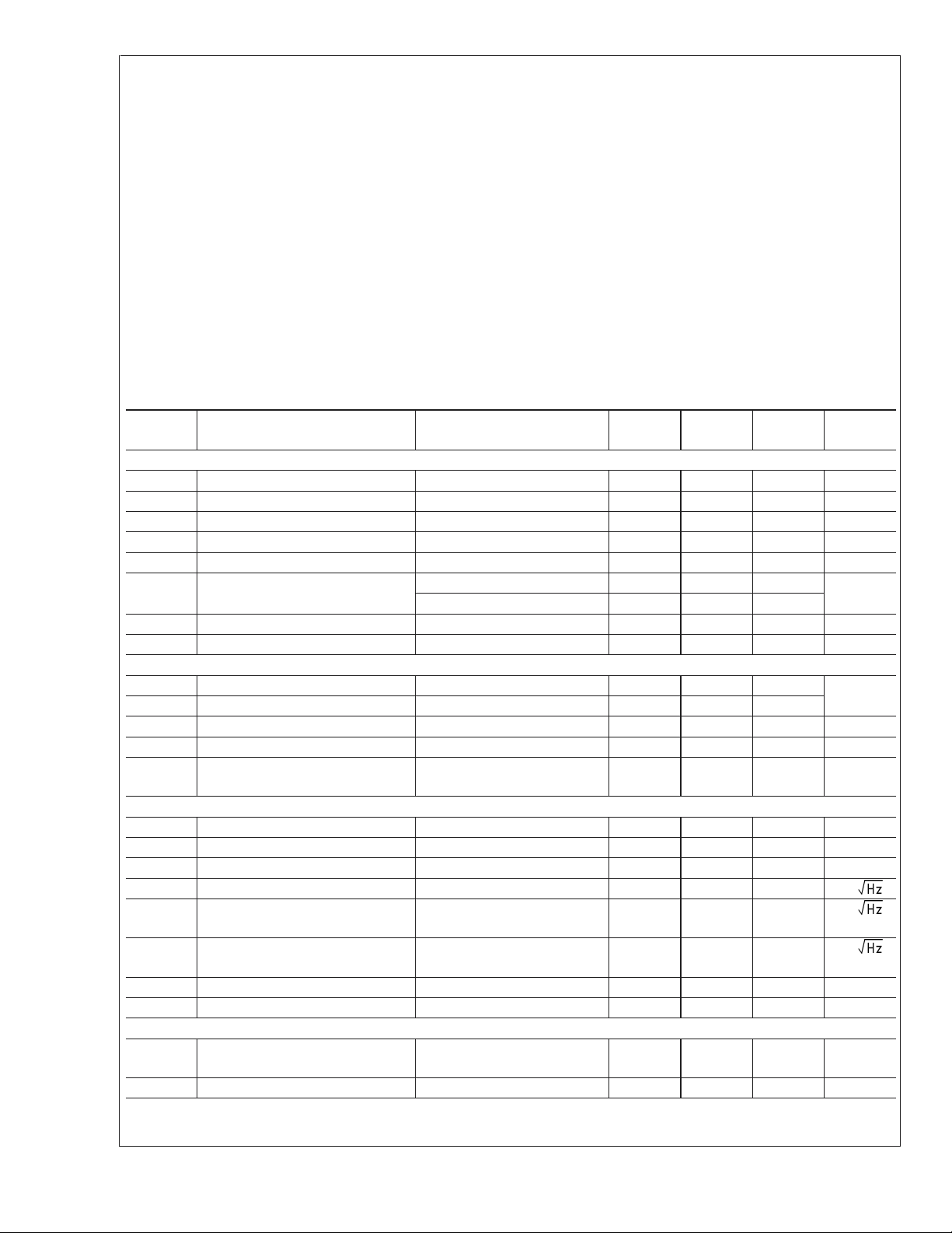
n Exceptional Performance at any Supply Current:
=±5V, TA= 25˚C, AV= +2V/V, V
V
S
unless Noted:
-3dB
I
CC
(mA)
n Ultra High Speed (−3dB BW) 1.5GHz (I
n Single resistor adjustability of supply current
n Fast enable/ disable capability 20ns (I
n "Popless" output on "Enable" 15mV (I
n Ultra low disable current
n Unity gain stable
n Improved Replacement for CLC505 & CLC449
BW
(MHz)
1.0 55 0.020/ 0.036 400 -70.0 9
3.4 180 0.022 / 0.017 2100 -78.5 45
9.0 540 0.025 / 0.010 2700 -79.6 115
DG/DP (%/
deg.)
PAL
Slew
Rate
(V/µs)
=2VPP, Typical
OUT
THD
1MHz
(dBc)
CC
0.25V
CC
CC
Applications
n Battery powered systems
n Video switching and distribution
n Remote site instrumentation
n Mobile communications gear
Output
Current
(mA)
= 10mA,
PP
= 9mA)
= 1mA)
<
1µA
)
−3dB BW vs. I
© 2004 National Semiconductor Corporation DS200602 www.national.com
CC
20060262
Turn-On/Off Characteristics
20060250
Absolute Maximum Ratings (Note 1)
If Military/Aerospace specified devices are required,
please contact the National Semiconductor Sales Office/
LMH6732
Human Body Model 2000V
Machine Model 200V
Distributors for availability and specifications.
±
V
S
I
OUT
I
CC
Common Mode Input Voltage V
6.75V
(Note 3)
14mA
−
to V
Maximum Junction Temperature +150˚C
Storage Temperature Range −65˚C to +150˚C
Soldering Information
Infrared or Convection (20 sec) 235˚C
+
Operating Ratings (Note 1)
Thermal Resistance
Package θ
8-Pin SOIC 65˚C/W 166˚C/W
6-Pin SOT23 120˚C/W 198˚C/W
Operating Temperature −40˚C to +85˚C
Nominal Supply Voltage
Operating Supply Current 0.5mA
(˚C/W) θJA(˚C/W)
JC
±
4.5V to±6V
Wave Soldering (10 sec) 260˚C
ESD Tolerance (Note 4)
Electrical Characteristics ICC= 9mA (Note 2)
AV= +2, RF= 700Ω,VS=±5V, RL= 100Ω,RP= 39kΩ; Unless otherwise specified.
Min
Symbol Parameter Conditions
(Note 6)
Frequency Domain Response
SSBW -3dB Bandwidth V
LSBW -3dB Bandwidth V
GF
0.1dB
0.1dB Gain Flatness V
GFP Frequency Response Peaking DC to 200MHz, V
GFR Frequency Response Rolloff DC to 200MHz, V
LPD Linear Phase Deviation DC to 200MHz, V
DG Differential Gain R
DP Differential Phase R
=2V
OUT
OUT
OUT
DC to 140MHz, V
L
L
PP
= 4.0V
PP
=2V
PP
=2V
OUT
OUT
OUT
OUT
=2V
=2V
=2V
PP
PP
PP
PP
= 150Ω, 4.43MHz 0.025 %
= 150Ω, 4.43MHz 0.010 deg
Time Domain Response
TRS Rise Time 2V Step 0.8
TRL Fall Time 2V Step 0.9
T
S
Settling Time to 0.04% AV= −1, 2V Step 18 ns
OS Overshoot 2V Step 1 %
SR Slew Rate 5V Step, 40% to 60%
(Note 5)
Distortion And Noise Response
HD2 2nd Harmonic Distortion 2V
HD3 3rd Harmonic Distortion 2V
THD Total Harmonic Distortion 2V
V
N
I
N
Input Referred Voltage Noise
Input Referred Inverting Noise
, 20MHz −60 dBc
PP
, 20MHz −64 dBc
PP
, 1MHz −79.6 dBc
PP
>
1MHz 2.5 nV/
>
1MHz 9.7 pA/
Current
I
NN
Input Referred Non-Inverting Noise
>
1MHz 1.8 pA/
Current
SNF Noise Floor
>
1MHz −154 dBm
INV Total Integrated Input Noise 1MHz to 200MHz 60 µV
Static, DC Performance
V
DV
IO
IO
Input Offset Voltage
Input Offset Voltage Average Drift (Note 8) 16 µV/˚C
Typ
(Note 6)
Max
(Note 6) Units
540 MHz
315 MHz
180 MHz
0.01 dB
0.15 dB
0.6
0.1
2700 V/µs
±
3.0
±
8.0
9.9
<
I
CC
12mA
deg
ns
mV
<
1Hz
www.national.com 2

Electrical Characteristics ICC= 9mA (Note 2) (Continued)
AV= +2, RF= 700Ω,VS=±5V, RL= 100Ω,RP= 39kΩ; Unless otherwise specified.
Min
Symbol Parameter Conditions
I
BN
DI
BN
I
BI
DI
BI
+PSRR Positive Power Supply Rejection
Input Bias Current Non Inverting (Note 7) −2
Input Bias Current Average Drift Non-Inverting (Note 8) 5 nA/˚C
Input Bias Current Inverting (Note 7) −9
Input Bias Current Average Drift Inverting (Note 8) −14 nA/˚C
DC 52
Ratio
−PSRR Negative Power Supply Rejection
DC 51
Ratio
CMRR Common Mode Rejection Ratio DC 49
I
CC
Supply Current RL=∞,RP= 39kΩ 7.5
ICCI Supply Current During Shutdown
Miscellaneous Performance
R
IN
C
IN
R
OUT
V
O
V
OL
Input Resistance Non-Inverting 4.7 MΩ
Input Capacitance Non-Inverting 1.8 pF
Output Resistance Closed Loop 32 mΩ
Output Voltage Range RL=
∞
RL= 100Ω
CMIR Common Mode Input Range Common Mode
I
O
Output Current Closed Loop
−40mV ≤ V
≤ 40mV
O
TON Turn-on Time 0.5VPPSine Wave, 90% of
Full Value
TOFF Turn-off Time 0.5V
Sine Wave,<5% of
PP
Full Value
V
O glitch
FDTH Feed-Through f = 10MHz, A
Turn-on Glitch 50 mV
= +2, Off State −61 dB
V
(Note 6)
50
48
46
6.6
±
3.60
±
3.55
±
2.90
±
2.85
±
75
LMH6732
Typ
(Note 6)
62 dB
56 dB
52 dB
9.0 10.5
<
1µA
±
3.75
±
3.10
±
2.2 V
±
115 mA
20
9
Max
(Note 6) Units
±
11
±
12
±
20
±
30
µA
µA
mA
11.7
V
ns
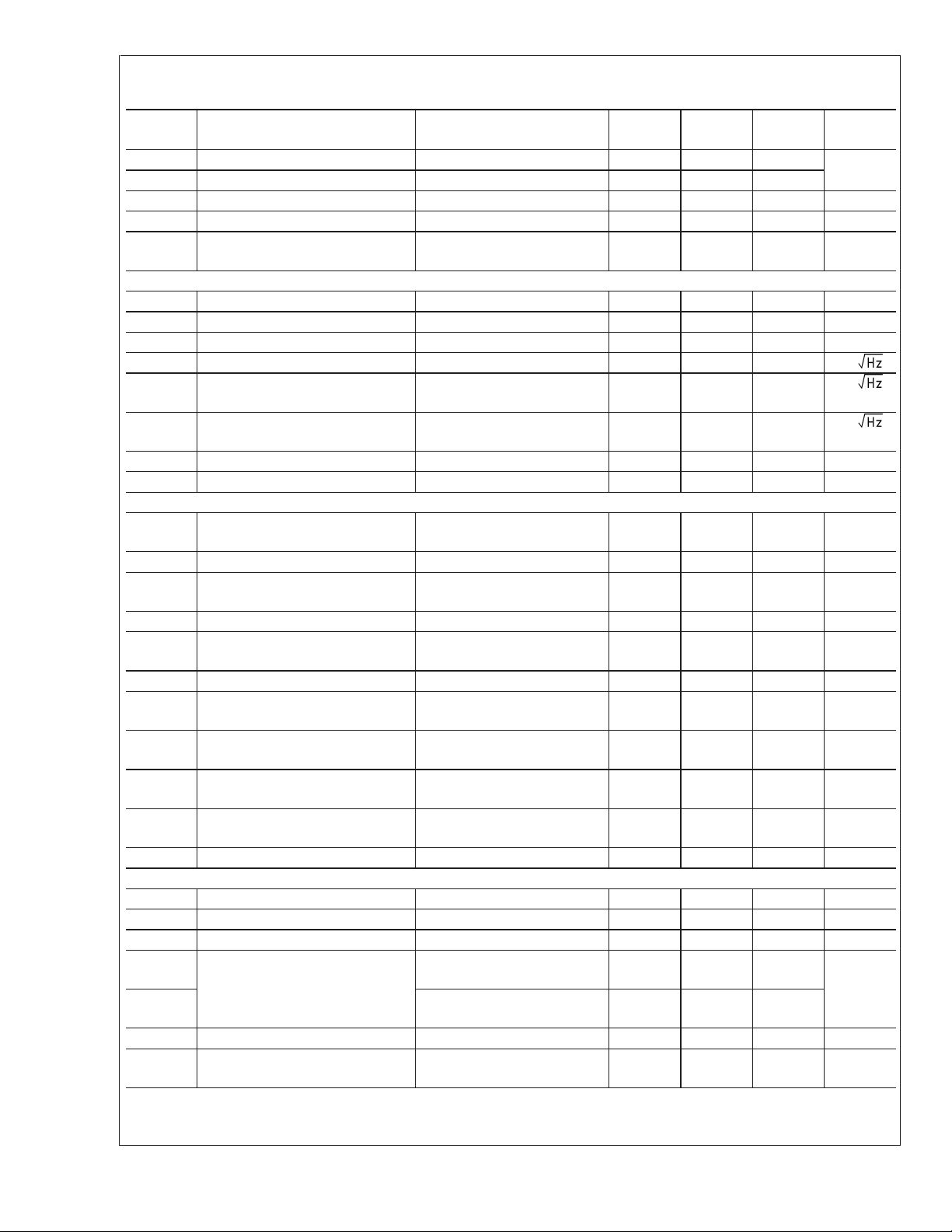
Electrical Characteristics ICC= 3.4mA (Note 2)
AV= +2, RF=1kΩ,VS=±5V, RL= 100Ω,RP= 137kΩ; Unless otherwise specified.
Symbol Parameter Conditions
Frequency Domain Response
SSBW -3dB Bandwidth V
LSBW -3dB Bandwidth V
GF
0.1dB
0.1dB Gain Flatness V
GFP Frequency Response Peaking DC to 75MHz, V
GFR Frequency Response Rolloff DC to 75MHz, V
LPD Linear Phase Deviation DC to 55MHz, V
DG Differential Gain R
DP Differential Phase R
Time Domain Response
=2V
OUT
OUT
OUT
DC to 25MHz, V
L
L
PP
= 4.0V
PP
=2V
PP
=2V
OUT
OUT
OUT
OUT
=2V
=2V
=2V
PP
PP
PP
PP
= 150Ω, 4.43MHz 0.022 %
= 150Ω, 4.43MHz 0.017 deg
Min
(Note 6)
Typ
(Note 6)
Max
(Note 6) Units
180 MHz
100 MHz
50 MHz
0.15 dB
0.05 dB
0.5
0.1
www.national.com3
deg
Electrical Characteristics ICC= 3.4mA (Note 2) (Continued)
AV= +2, RF=1kΩ,VS=±5V, RL= 100Ω,RP= 137kΩ; Unless otherwise specified.
LMH6732
Symbol Parameter Conditions
TRS Rise Time 2V Step 1.7
TRL Fall Time 2V Step 2.1
T
S
OS Overshoot 2V Step 2 %
SR Slew Rate 5V Step, 40% to 60%
Distortion And Noise Response
HD2 2nd Harmonic Distortion 2V
HD3 3rd Harmonic Distortion 2V
THD Total Harmonic Distortion 2V
V
N
I
N
I
NN
SNF Noise Floor
INV Total Integrated Input Noise 1MHz to 100MHz 60 µV
Static, DC Performance
V
IO
DV
IO
I
BN
DI
BN
I
BI
DI
BI
+PSRR Positive Power Supply Rejection
−PSRR Negative Power Supply Rejection
CMRR Common Mode Rejection Ratio DC 49
I
CC
ICCI Supply Current During Shutdown
Miscellaneous Performance
R
IN
C
IN
R
OUT
V
O
V
OL
CMIR Common Mode Input Range Common Mode
I
O
Settling Time to 0.04% AV= −1, 2V Step 18 ns
(Note 5)
, 10MHz −51 dBc
PP
, 10MHz −65 dBc
PP
, 1MHz −78.5 dBc
PP
Input Referred Voltage Noise
Input Referred Inverting Noise
>
1MHz 4.1 nV/
>
1MHz 8.8 pA/
Current
Input Referred Non-Inverting Noise
>
1MHz 1.1 pA/
Current
>
1MHz −151 dBm
Input Offset Voltage
Input Offset Voltage Average Drift (Note 8) 10 µV/˚C
Input Bias Current Non Inverting (Note 7) −0.4
Input Bias Current Average Drift Non-Inverting (Note 8) 8 nA/˚C
Input Bias Current Inverting (Note 7) −1
Input Bias Current Average Drift Inverting (Note 8) −3 nA/˚C
DC 52
Ratio
DC 51
Ratio
Supply Current RL=∞,RP= 137kΩ 2.8
Input Resistance Non-Inverting 15 MΩ
Input Capacitance Non-Inverting 1.7 pF
Output Resistance Closed Loop 50 mΩ
Output Voltage Range RL=
∞
RL= 100Ω
Output Current Closed Loop
−20mV ≤ V
≤ 20mV
O
Min
(Note 6)
50
50
48
2.6
±
3.60
±
3.55
±
2.90
±
2.85
±
30
Typ
(Note 6)
Max
(Note 6) Units
2100 V/µs
±
2.5
±
7.0
±
8.5
±
4
±
6
±
12
±
16
64 dB
57 dB
55 dB
3.4 3.9
4.1
<
1µA
±
3.78
±
3.10
±
2.2 V
±
45 mA
ns
1Hz
mV
µA
µA
mA
V
www.national.com 4

Electrical Characteristics ICC= 3.4mA (Note 2) (Continued)
AV= +2, RF=1kΩ,VS=±5V, RL= 100Ω,RP= 137kΩ; Unless otherwise specified.
Symbol Parameter Conditions
TON Turn-on Time 0.5V
Sine Wave, 90% of
PP
Full Value
TOFF Turn-off Time 0.5V
Sine Wave,<5% of
PP
Min
(Note 6)
Typ
(Note 6)
42
10
Max
(Note 6) Units
ns
Full Value
V
O glitch
FDTH Feed-Through f = 10MHz, A
Turn-on Glitch 25 mV
= +2, Off State −61 dB
V
Electrical Characteristics ICC= 1.0mA (Note 2)
AV= +2, RF=1kΩ,VS=±5V, RL= 500Ω,RP= 412kΩ; Unless otherwise specified.
Min
Symbol Parameter Conditions
(Note 6)
Frequency Domain Response
SSBW -3dB Bandwidth V
LSBW -3dB Bandwidth V
GF
0.1dB
0.1dB Gain Flatness V
GFP Frequency Response Peaking DC to 25MHz, V
GFR Frequency Response Rolloff DC to 25MHz, V
LPD Linear Phase Deviation DC to 20MHz, V
DG Differential Gain R
DP Differential Phase R
=2V
OUT
OUT
OUT
DC to 14MHz, V
L
L
PP
= 4.0V
PP
=2V
PP
=2V
OUT
OUT
OUT
OUT
=2V
=2V
=2V
PP
PP
PP
PP
= 500Ω, 4.43MHz 0.020 %
= 500Ω, 4.43MHz 0.036 deg
Time Domain Response
TRS Rise Time 2V Step 3.7
TRL Fall Time 2V Step 5.1
T
S
Settling Time to 0.04% AV= −1, 2V Step 18 ns
OS Overshoot 2V Step 2 %
SR Slew Rate 5V Step, 40% to 60%
(Note 5)
Distortion And Noise Response
HD2 2nd Harmonic Distortion 2V
HD3 3rd Harmonic Distortion 2V
THD Total Harmonic Distortion 2V
V
N
I
N
Input Referred Voltage Noise
Input Referred Inverting Noise
, 5MHz −43 dBc
PP
, 5MHz −65 dBc
PP
, 1MHz −70.0 dBc
PP
>
1MHz 8.4 nV/
>
1MHz 9.0 pA/
Current
I
NN
Input Referred Non-Inverting Noise
>
1MHz 0.8 pA/
Current
SNF Noise Floor
>
1MHz −147 dBm
INV Total Integrated Input Noise 1MHz to 100MHz 29 µV
Static, DC Performance
V
DV
I
BN
DI
I
BI
IO
IO
BN
Input Offset Voltage
Input Offset Voltage Average Drift (Note 8) 4 µV/˚C
Input Bias Current Non Inverting (Note 7) 0.04
Input Bias Current Average Drift Non-Inverting (Note 8) −1 nA/˚C
Input Bias Current Inverting (Note 7) −0.1
Typ
(Note 6)
Max
(Note 6) Units
55 MHz
30 MHz
20 MHz
0.11 dB
0.05 dB
1
0.3
400 V/µs
±
1.6
±
6.0
±
7.3
±
2.0
±
2.5
±
6
±
8
deg
ns
mV
µA
µA
LMH6732
1Hz
www.national.com5

Electrical Characteristics ICC= 1.0mA (Note 2) (Continued)
AV= +2, RF=1kΩ,VS=±5V, RL= 500Ω,RP= 412kΩ; Unless otherwise specified.
LMH6732
Symbol Parameter Conditions
DI
BI
+PSRR Positive Power Supply Rejection
−PSRR Negative Power Supply Rejection
CMRR Common Mode Rejection Ratio DC 49
I
CC
ICCI Supply Current During Shutdown
Miscellaneous Performance
R
IN
C
IN
R
OUT
V
O
V
OL
CMIR Common Mode Input Range Common Mode
I
O
TON Turn-on Time 0.5V
TOFF Turn-off Time 0.5V
V
O glitch
FDTH Feed-Through f = 10MHz, A
Note 1: Absolute Maximum Ratings indicate limits beyond which damage to the device may occur. Operating Ratings indicate conditions for which the device is
intended to be functional, but specific performance is not guaranteed. For guaranteed specifications, see the Electrical Characteristics tables.
Note 2: Electrical Table values apply only for factory testing conditions at the temperature indicated. Factory testing conditions result in very limited self-heating of
the device such that T
Min/Max ratings are based on production testing unless otherwise specified.
Note 3: The maximum output current (I
Note 4: Human body model: 1.5kΩ in series with 100pF. Machine model: 0Ω in series with 200pF.
Note 5: Slew Rate is the average of the rising and falling edges.
Note 6: Typical numbers are the most likely parametric norm. Bold numbers refer to over temperature limits.
Note 7: Negative input current implies current flowing out of the device.
Note 8: Drift determined by dividing the change in parameter distribution average at temperature extremes by the total temperature change.
Input Bias Current Average Drift Inverting (Note 8) −3 nA/˚C
DC 52
Ratio
DC 51
Ratio
Supply Current RL=∞,RP= 412kΩ 0.70
Input Resistance Non-Inverting 46 MΩ
Input Capacitance Non-Inverting 1.7 pF
Output Resistance Closed Loop 100 m Ω
Output Voltage Range RL=
∞
RL= 500Ω
Output Current Closed Loop
−15mV ≤ V
PP
≤ 15mV
O
Sine Wave, 90% of
Full Value
Sine Wave,<5% of
PP
Full Value
Turn-on Glitch 15 mV
= +2, Off State −61 dB
V
. No guarantee of parametric performance is indicated in the electrical tables under conditions of internal self-heating where T
J=TA
) is determined by device power dissipation limitations.
O
Min
(Note 6)
51
49
47
0.66
±
3.60
±
3.55
±
2.90
±
2.85
±
6
Typ
(Note 6)
Max
(Note 6) Units
64 dB
59 dB
55 dB
1.0 1.3
1.4
<
1µA
±
3.78
±
3.10
±
2.2 V
±
9mA
95
40
mA
J
ns
>
V
TA.
www.national.com 6
 Loading...