

National Semiconductor LM5072 User Manual
LM5072 12Vout 25W PoE PD
Power Eval-Board for IP
Camera
National Semiconductor
LM5072
Honsun Tan
February 2008
1.0 Design Specifications
Inputs Output #1
VinMin=38V Vout1=12V
VinMax=60V Iout1=2.1A
2.0 Design Description
This LM5072 25W PoE PD Power Eval-board is specially designed for IP Net Cameras powered by PoE. As the PD side's
power converter of a PoE system, this Eval-board converts
48Vdc to 12Vdc to directly power the motor driver for the IP
Net Camera's body rotation and zoom lens. Other regulators
such as LM26400 from National Semiconductor can be used
to convert the 12Vdc to 3.3Vdc, 2.5Vdc, 1.8Vdc and 1.2Vdc
to power the processor of an IP Net Camera as shown in figure 11. This board can provide total power up to 25W as
specified by the PoE Plus IEEE802.3at standard. In addition,
this Eval-board can be interfaced to any PSE that follows detection and classification procedures defined by the
IEEE802.3af standard. In summary, this Eval-board is the
ideal solution for a Pre-PoE Plus IP Net Camera application.
This design has 2 auxilliary inputs to allow use of inexpensive
12Vdc and 24Vac regulated adapters to take advantage of
the LM5072's versatile auxiliary power options. 12Vdc power
can by provided to the load, bypassing the LM5072, by connecting a 12Vdc regulated adapter to the 12V AUX Input Port.
When regulated 12Vdc is available, it can be delivered directly
to the load, bypassing the LM5072, by connecting to the 12V
AUX Input Port. When the regulated 12Vdc is present at the
12V AUX input port before 48V PoE voltage is present, the
PoE startup signature detection resistance of the PD is significantly reduced. This signals the PSE to not deliver power
to the PD. If 12Vdc is added after 48V PoE voltage is present,
the PD signature resistance changes and will signal the PSE
to stop providing power to the PD. In either case the regulated
12Vdc will turn off the LM5072 and can reduce power losses
from the converter and the PoE line.
The LM5072's RAUX configuration is utilized for the 24V AUX
input port to bypass the internal hot swap MOSFET allowing
the 800mA current limit of the LM5072 to be ignored. This
allows the input voltage for the 24V AUX input port to go down
to 16Vdc and up to 60Vdc. A key function for automatic selection of supply Dominance Option is implemented for the
24V AUX input port. By connecting pin 1 and pin 2 by a
jumper, as shown in figure 4, the 24V AUX is made to be the
dominant input voltage, even if 48V PoE input voltage is
present. Alternatively, if pin 2 and pin 3 are jumpered, as
shown in figure 4, the LM5072 will be placed in non-dominance mode.
The theory and general application of PoE is beyond the
scope of this document. For detailed PoE information, please
see the LM5072 datasheet.
This document includes a schematic, BOM, layout and detailed test results.
3.0 Features
Energy Efficient Eval-Board
DC/DC converter efficiency of 89% at PoE 48Vin with 25W
Load.
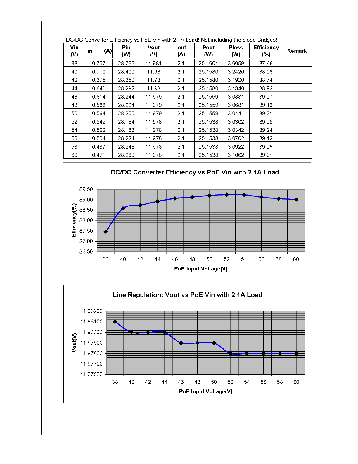
Overall efficiency of 85.5% at PoE 48Vin with 25W load.
DC/DC converter efficiency of 90% at 24Vin with 25W load.
Overall efficiency of 89% at 24Vin with 25W load.
Versatile Input Power Options
PoE input Port: 38Vdc-60Vdc range with PoE interface.
24V AUX input Port: 24Vac from inexpensive 24Vac adapter
or 16Vdc-60Vdc range
12V AUX input Port: Regulated 12Vdc from inexpensive
12Vdc adapter.
Full Protection for PoE
Compliant 802.3af PD interface
Inrush current limit.
Accurate 800mA over current protection.
Short-circuit protection, hiccup mode.
Input UVLP with 7V hysteresis, 37V on and 30V shutdown
LED indicates power from PoE
Uses Standard Transformer FA2900 from Coilcraft
This Eval-board is easily modified to 3.3Vdc, 5Vdc, 9Vdc and
15Vdc output with standard Coilcraft transformers FA2677,
FA2898, FA2899 and FA2901 respectively.
© 2008 National Semiconductor Corporation www.national.com
LM5072 12Vout 25W PoE PD Power Eval-Board for IP Camera LM5072
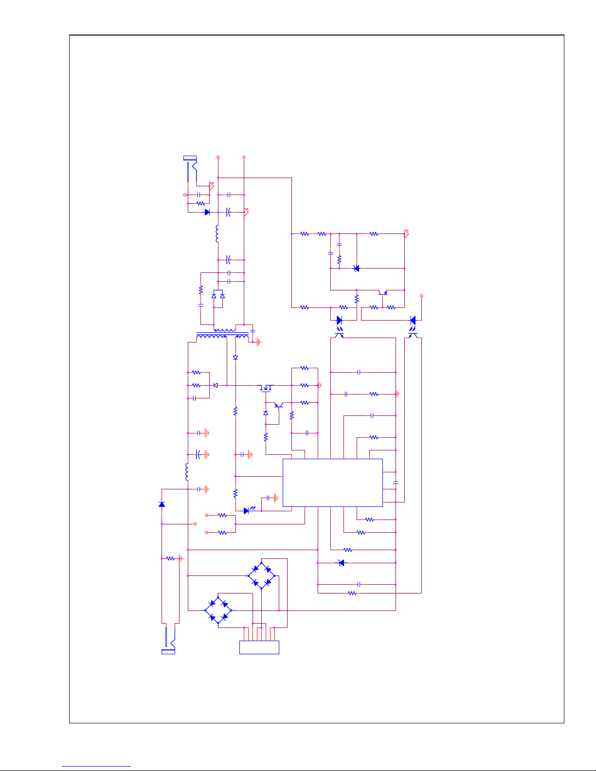
4.0 Schematic
0
12Vout
GND
31
2
12V AUX
12V AUX
24V AUX Input Port
24V AUX Domination Option
ECJ4YB1E226M
SMA
74456115
100V
0805
EEEFK1V331P
DO1813-181ML
SMA
12V AUX Input Port
SMA
DPAK
DPAK
1206
1210
1210
1210
1210
1206 1206 1206
1206
1206 1206 0805
SO-123
SO-1230805
0805
1812
1206
0805
80V
100V
Port
R25
5.11k
R25
5.11k
C13
0.047uF
C13
0.047uF
U4
SFH6156-2
U4
SFH6156-2
1 2
4 3
R22
15.8k
R22
15.8k
R10
100ohm
R10
100ohm
-+
BR2
CBRHD-01
-+
BR2
CBRHD-01
1
4
3
2
D2
CMSH3-20MA
D2
CMSH3-20MA
R17
100K
R17
100K
C19NIC19
NI
C18
0.047uF
C18
0.047uF
C1
4.7uF/100V
C1
4.7uF/100V
C10
22uF
C10
22uF
R29NIR29
NI
C9330uF/35V C9330uF/35V
C12
2200pF/2kV
C12
2200pF/2kV
C11
2.2uF/25V
C11
2.2uF/25V
R27
10k
R27
10k
C8
22uF/25VC822uF/25V
R18
20k
R18
20k
C2
47uFC247uF
R26
5.11K
R26
5.11K
J1J1
1
2
C5
1000pFC51000pF
-+
BR1
CBRHD-01
-+
BR1
CBRHD-01
1
4
3
2
R1
24.9KR124.9K
R13
0.33
R13
0.33
C17
0.047uF
C17
0.047uF
J2J2
1
2
C15NIC15
NI
R2
20KR220K
R12
0.33
R12
0.33
R23
21.5k
R23
21.5k
Q3
BC817-16Q3BC817-16
C3
4.7uF/100V
C3
4.7uF/100V
D1
CMSH3-60M
D1
CMSH3-60M
J3
PoEJ3PoE
1234567
8
R24
680ohm
R24
680ohm
R6
140kR6140k
C6
22uFC622uF
R19NIR19
NI
U1
LM5072U1LM5072
OUT
9
nPGOOD
11
CS
12
VIN
3
SS
2RT1
COMP
15
ARTN
16
ICL_FAUX
5
FB
14
DCCL
6
RTN
8
VCC
10
VEE
7
RCLASS
4
RAUX
13
EP
D5
CMMR1F-02
D5
CMMR1F-02
R8
33ohmR833ohm
R11
0.33
R11
0.33
R20
10k
R20
10k
Q2
BCX53Q2BCX53
R4
10ohmR410ohm
C27
150uF/16V
C27
150uF/16V
L1
15uHL115uH
1 2
Q1
SUD25N15
Q1
SUD25N15
U3
LM431U3LM431
D4
CMMR1U-02
D4
CMMR1U-02
R3
20kR320k
R7
3.32KR73.32K
R15
845ohm
R15
845ohm
D8
SMAJ58D8SMAJ58
C21
0.047uF
C21
0.047uF
C16
4700pF
C16
4700pF
R21
33k
R21
33k
C7
22uF/25VC722uF/25V
D6
LEDD6LED
C4
4700pF/250V
C4
4700pF/250V
U2
SFH6156-2
U2
SFH6156-2
12
43
D7
CMMR1F-02
D7
CMMR1F-02
R5
4.99kR54.99k
R280R28
0
R16
18.7K
R16
18.7K
T1
FA2900T1FA2900
1,2
10,11,12
3,4
7,8,95
6
R14
2.49k
R14
2.49k
C14
1000pF
C14
1000pF
C20
0.47uF
C20
0.47uF
R9
2.2ohmR92.2ohm
L2
0.18uHL20.18uH
1 2
D3
CSHD6-60C
D3
CSHD6-60C
schematic
FIGURE 1. Schematic
www.national.com 2
LM5072

5.0 Bill of Materials
bom
FIGURE 2. BOM
3 www.national.com
LM5072
6.0 Other Operating Values
Operating Values
Description Parameter Value Unit
Modulation Frequency Frequency 250 KHz
Total output power Pout 25 W
Steady State Efficiency Efficiency 85 %
Control scheme Control scheme current Mode
Peak-to-peak ripple voltage Vout p-p 50 mV
Static load regulation Static load 100 mV
Dynamic load regulation Dynamic load 250 mV
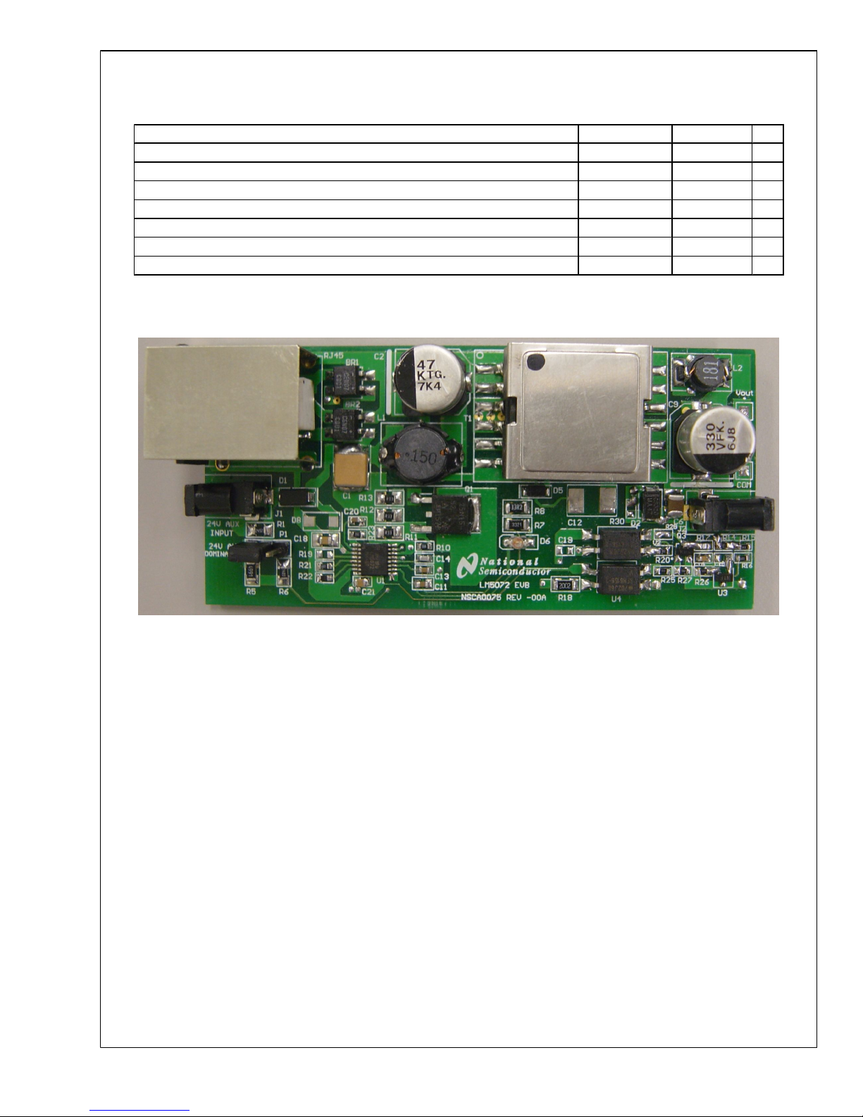
7.0 Board Photos
boardphoto1
FIGURE 3. Eval-board Photo
8.0 Layouts
www.national.com 4
LM5072
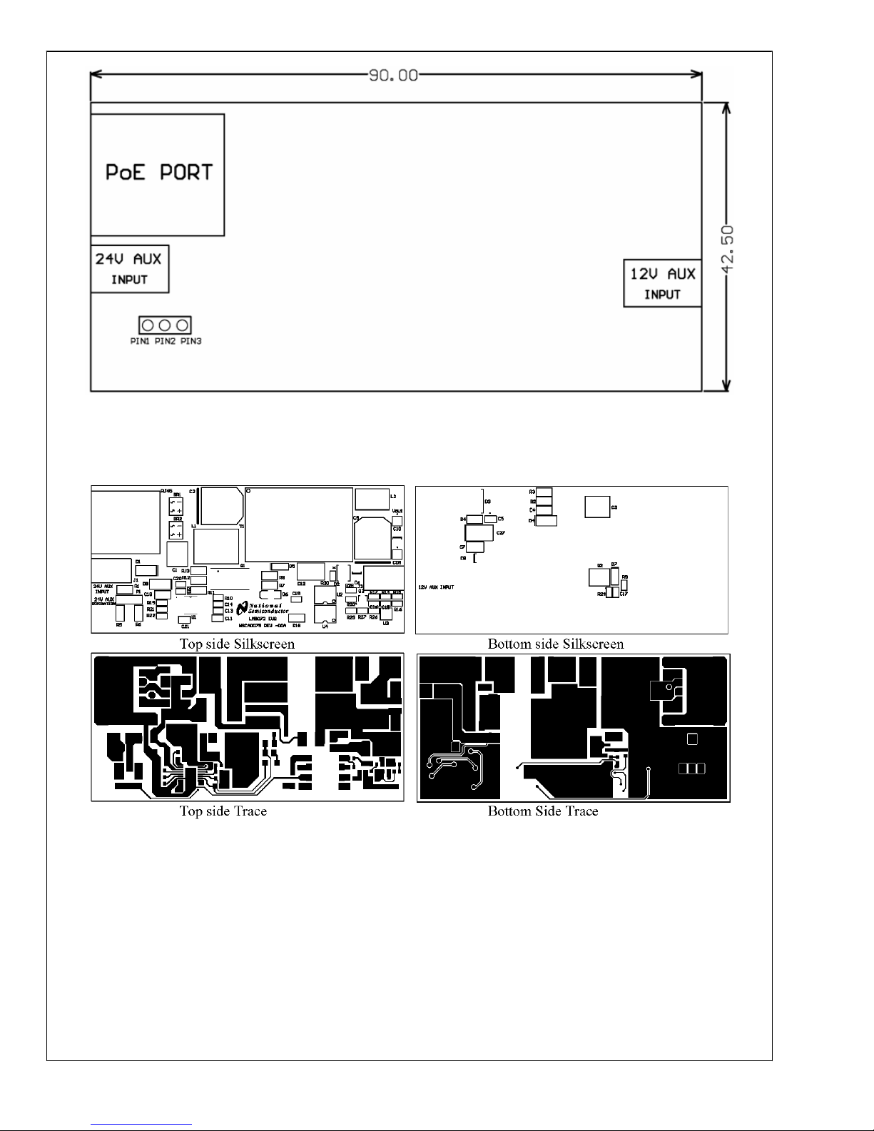
layout
FIGURE 4. PCB Board Outline
layout1
FIGURE 5. Layout Drawing
9.0 Waveforms
5 www.national.com
LM5072
waveform
FIGURE 6. DC to DC Converter Efficiency at PoE Input
www.national.com 6
LM5072
 Loading...