

Page 1

™
MXI
Getting Started with Your
VXI/VME-PCI8026 and the
NI-VXI™/NI-VISA™ Software
for Linux
VXI/VME-PCI8026 for Linux
December 1999 Edition
Part Number 322651A-01
Page 2

Worldwide Technical Support and Product Information
www.ni.com
National Instruments Corporate Headquarters
11500 North Mopac Expressway Austin, Texas 78759-3504 USA Tel: 512 794 0100
Worldwide Offices
Australia 03 9879 5166, Austria 0662 45 79 90 0, Belgium 02 757 00 20, Brazil 011 284 5011,
Canada (Calgary) 403 274 9391, Canada (Ontario) 905 785 0085, Canada (Québec) 514 694 8521,
China 0755 3904939, Denmark 45 76 26 00, Finland 09 725 725 11, France 01 48 14 24 24,
Germany 089 741 31 30, Greece 30 1 42 96 427, Hong Kong 2645 3186, India 91805275406,
Israel 03 6120092, Italy 02 413091, Japan 03 5472 2970, Korea 02 596 7456, Mexico (D.F.) 5 280 7625,
Mexico (Monterrey) 8 357 7695, Netherlands 0348 433466, Norway 32 27 73 00, Poland 48 22 528 94 06,
Portugal 351 1 726 9011, Singapore 2265886, Spain 91 640 0085, Sweden 08 587 895 00,
Switzerland 056 200 51 51, Taiwan 02 2377 1200, United Kingdom 01635 523545
For further support information, see the Technical Support Resources appendix. To comment on the
documentation, send e-mail to [email protected]
© Copyright 1999 National Instruments Corporation. All rights reserved.
Page 3

Important Information
Warranty
The National Instruments MXIbus boards and accessories are warranted agai nst defects in materi als and workmanship for a period
of one year from the date of shipment, as evidenced by recei pt s or o th er do cum e ntat io n. Natio nal Inst rume nts wi ll , at i ts opti on,
repair or replace equipment that proves to be defective during the warranty period. This warranty includes parts and labor.
The media on which you receive National Instruments software are warranted not to fail to execute programming instructions,
due to defects in materials and workmanship, for a period of 90 days from date o f sh ip men t, as ev id enced b y recei pt s o r other
documentation. National Instruments will, at its op tion , repai r or replace s oft ware me dia th at do not ex ecute p rog ram mi ng
instructions if National Instruments receives notice of such defects during the warranty period. National Instruments does not
warrant that the operation of the software shall be unint errup ted or error free.
A Return Material Authorization (RMA) number must be obtained from the factory and clearly marked on the outside of
the package before any equipment will be accepted for warranty work. National Instruments will pay the shipping costs of
returning to the owner parts which are covered by warranty.
National Instruments believes that the information in this document is accurate. The document has been carefully reviewed
for technical accuracy. In the event that technical or typographical errors exist, National Instruments reserves the right to
make changes to subsequent editions of this document with ou t p rio r no ti ce to h old ers o f t hi s ed itio n. The read er sh ou ld cons ul t
National Instruments if errors are suspected. In no even t shal l Nation al In st rume nts be l iable fo r any dam ages aris in g out of
or related to this document or the information contained in it.
XCEPT AS SPECIFIED HEREIN
E
WARRANTY OF MERCHANTABILITY OR FITNESS FOR A PARTICULAR PURPOSE
NEGLIGENCE ON THE PART OF NATIONAL INSTRUMENTS SHALL BE LIMITED TO THE AMOUNT THERETOFORE PAID BY THE CUSTOMER
NSTRUMENTS WILL NOT BE LIABLE FOR DAMAGES RESULTING FROM LOSS OF DATA, PROFITS, USE OF PRODUCTS, OR INCIDENTAL OR
I
CONSEQUENTIAL DAMAGES, EVEN IF ADVISED OF THE POSSIBILITY THEREOF
apply regardless of the form of action, whether in contract or tort, including negligence. Anyaction against National Instruments
must be brought within one year after the cause of action accrues. National Instruments shall not be liable for any delay in
performance due to causes beyond its reasonable control. The warrant y p rovided herei n does no t cover d a mage s, defects,
malfunctions, or service failures caused by owner’s failure to fo ll ow th e Nati on al Inst rume nt s in stal l ati on, op erat ion, or
maintenance instructions; owner’s modification of the product; owner’s abuse, misuse, or negligent act s; and po wer failure or
surges, fire, flood, accident, actions of third parties, or other events outside reasonable control.
ATIONAL INSTRUMENTS MAKES NO WARRANTIES, EXPRESS OR IMPLIED, AND SPECIFICALLY DISCLAIMS ANY
, N
USTOMER’S RIGHT TO RECOVER DAMAGES CAUSED BY FAULT OR
. C
. This limitation of the liability of National Instruments will
. N
ATIONAL
Copyright
Under the copyright laws, this publication may not be reproduced or transmitted in any form, electronic or mechanical, including
photocopying, recording, storing in an info rmatio n ret riev al s ystem , o r tr an slati ng , in who le o r i n part, wit ho ut t he prior written
consent of National Instruments Corporation.
Trademarks
LabVIEW™, National Instruments™, ni.com™, NI-VISA™, NI-VXI™, and VXIpc™ are trademarks of National Instruments
Corporation.
Product and company names mentioned herein are trad em arks o r trade nam es of t hei r respect iv e com panies .
WARNING REGARDING USE OF NATIONAL INSTRUMENTS PRODUCTS
(1) NATIONAL INSTRUMENTS PRODUCTS ARE NOT DESIGNED WITH COMPONENTS AND TESTING FOR A LEVEL
OF RELIABILITY SUITABLE FOR USE IN OR IN CONNECTION WITH SURGICAL IMPLANTS OR AS CRITICAL
COMPONENTS IN ANY LIFE SUPPORT SYSTEMS WHOSE FAILURE TO PERFORM CAN RE ASONA BLY BE
EXPECTED TO CAUSE SIGNIFICANT INJURY TO A HUMAN.
(2) IN ANY APPLICATI ON, INCLUDI NG THE ABOVE, RE LIABILITY OF OP ERATION OF THE SOFTWARE PROD UCTS
CAN BE IMPAIRED BY ADVERSE FACTORS, INCLUDING BUT NOT LIMITED TO FLUCTUATIONS IN ELECTRICAL
POWER SUPPLY, COMPUTER HARDWARE MALFUNCTIONS, COMPUTER OPERATING SYSTE M SOFTWARE
FITNESS, FITNESS OF COMPILERS AND DEVELOPMENT SOFTWARE USED TO DE VEL OP AN APPLICATION,
INSTALLATION ERRORS, SOFTWARE AND HARDWARE COMPATIBILITY PROBLEMS, MALFUNCTIONS OR
FAILURES OF ELECTRONIC MONITORING OR CONTROL DEVICES, TRANSIENT FAILURES OF ELECT RO NIC
SYSTEMS (HARDWARE AND/OR SOFTWARE), UNANTICIPATED USES OR MISUSES, OR ERRORS ON THE PART OF
THE USER OR APPLICATIONS DESIGNER (ADVERSE FACTORS SUCH AS THESE ARE HEREAFTER
COLLECTIVELY TERMED “SYSTEM FAILURES”). ANY APPLICATION WHERE A SYST EM FAILU RE WO ULD
CREATE A RISK OF HARM TO PROPERTY OR PERSONS (INCLUDING THE RISK OF BODILY INJURY AND DEATH)
SHOULD NOT BE RELIANT SOLELY UPON ONE FORM OF EL ECTRON IC SYSTE M DUE TO THE RISK OF SYSTEM
FAILURE. TO AVOID DAMAGE, INJURY, OR DEATH, THE USER OR APPLICATIO N D ESIGNER MU ST T AKE
REASONABLY PRUDENT STEPS TO PROTECT AGAINST SYSTEM FAILURES, INCLUDING BUT N OT LIM ITED TO
BACK-UP OR SHUT DOWN MECHANISMS. BECAUSE EACH END-USER SYSTEM IS CUSTOM IZE D AN D DIFFE RS
FROM NATIONAL INSTRUMENTS' TESTING PLATFORMS AND BECAUSE A USER OR APPL ICATION DESIGN ER
MAY USE NATIONAL INSTRUMENTS PRODUCTS IN COMBINATION WITH OTHER PRODUCTS IN A MANNER NOT
EVALUATED OR CONTEMPLATED BY NATIONAL INSTRUMENTS, TH E U SER OR A PPLICATION DE SIGNER IS
ULTIMATELY RESPONSIBLE FOR VERIFYING AND VALIDATING THE SUITA BILITY OF NA TION AL
INSTRUMENTS PRODUCTS WHENEVER NATIONAL INSTRUMENTS PRODUCTS ARE INCORPORATED IN A
SYSTEM OR APPLICATION, INCLUDING, WITHOUT LIMITATION, THE APPROPRIATE DE SIGN, PROCESS AN D
SAFETY LEVEL OF SUCH SYSTEM OR APPLICATION.
Page 4

Compliance
FCC/Canada Radio Frequency Interference Compliance*
Determining FCC Class
The Federal Communications Commission (FCC) has rules to protect wireless communications from interference.
The FCC places digital electronics into two classes. These classes are known as Class A (for use in industrialcommercial locations on ly ) or Cl ass B (for use in residential or commercia l locations). Depending on where it is
operated, this product could be sub je ct to restri ct io ns in t he FCC rul es. (In Canada, the Department of
Communications (DOC), of Industry Canada, regulates wireless interference in much the same way.)
Digital electronics emi t weak signals during normal operat ion that can affect radio, television, or othe r wireless
products. By examining the product you purchased, you can determine the FCC Class and therefore which of the two
FCC/DOC Warnings app ly in the following sections. (Some product s ma y not be labe ll e d at all for FCC, if so the
reader should then assume these are Class A devices.)
FCC Class A products only display a simple warning statement of one paragraph in length regarding interference and
undesired operation. Most of our products are FCC Class A. The FCC rules have restrictions regarding the locations
where FCC Class A products can be ope rated.
FCC Class B products display either a FCC ID code, starting with the letters EXN,
or the FCC Class B co mpliance mark that appears as shown here on the r ight.
The curious reader can consult the FCC web site
information.
FCC/DOC Warnings
This equipment generates and uses radio frequency energy and, if not installed and used in strict accordance with the
instructions in this manual and the CE Mark Declaration of Conformity**, may cause interference to radio and
television reception. Classification requirements are the same for the Federal Communications Commission (FCC)
and the Canadian Departm e nt of Communications (DOC).
Changes or modifications not expressly approved by National Instruments could void the user’s authority to operate
the equipment under the FCC Rules.
Class A
Federal Communications Commission
This equipment has been tested and found to comply with the limits for a Class A digital device, pursuant to part 15
of the FCC Rules. These limits are designed to provide reasonable protection against harmful interference when the
equipment is operated in a commercial environment. This equipment generates, uses, and can radiate radio frequency
energy and, if not instal le d a nd used in accordance with the instruction manual, may cause ha rm ful interference to
radio communication s. Ope r ation of this equipment in a residentia l ar ea is likely to cause harmful interfe r en ce in
which case the user will be required to correct the i nt erference at his own expense.
http://www.fcc.gov for more
Canadian Department of Communications
This Class A digital apparatus meets all requirements of the Canadian Interference-Causing Equipment Regulations.
Cet appareil numérique de la cla sse A respecte toutes les exigences du Règl em ent sur le matériel brouilleur du
Canada.
Class B
Federal Communications Commission
This equipment has been tested and found to comply with the limits for a Class B digital device, pursuant to part 15
of the FCC Rules. These limits a re designed to provide reasonable protection against harmful inte rfe rence in a
residential installation. This equipment generates, uses a nd can radiate radio frequency ene rgy and, if not installed
and used in accorda n ce w ith the instructions , may cause harmful interfe rence to radio communications. However,
there is no guarantee that interference will not occur in a particular installation. If this equipment does cause harmful
Page 5

interference to radio or television reception, which can be determined by turning the equipment off and on, the user
is encouraged to try to correct the interference by one or more of the following measures:
• Reorient or relocate the receiving antenna.
• Increase the separation between the equipment and receiver.
• Connect the equipment into an outlet on a circuit different from that to which the receiver is connected.
• Consult the dealer or an experienced radio/TV technician for help.
Canadian Department of Communications
This Class B digital apparatus meets all requirements of the Canadian Interference-Causing Equipment Regulations.
Cet appareil numérique de la classe B respecte toutes les exigences du Règlement sur le matériel brouilleur du
Canada.
European Union - Compliance to EEC Directives
Readers in the EU/EEC/EEA must refer to the Manufacturer's Declaration of Conformity (DoC) for information**
pertaining to the CE Mark compliance scheme. The M anu facturer includes a DoC f or mo st ever y hardware produ ct
except for those bought for OEMs, if also available from an original manufacturer that also markets in the EU, or
where compliance is not required as for electrically benign apparatus or cables.
* Certain exemptions may apply in the USA, see FCC Rules §15.103 Exempted devices, and §15.105(c). Also
available in sections of CFR 47.
** The CE Mark Declaration of Conformity will contain important supplementary information and instructions for
the user or installer.
Page 6

Contents
About This Manual
How To Use the Manual Set............................................................................................xiii
Conventions .....................................................................................................................xiv
Related Documentation....................................................................................................xv
Chapter 1
Introduction and Quick Start
How to Use This Manual............................................................ .....................................1-2
VXI/VME-PCI8026 Kit Overview..................................................................................1-3
What You Need to Get Started ........................................................... .............................1-3
MXI-2 Description...........................................................................................................1-3
Hardware Description......................................................................................................1-4
Software Description .......................................................................................................1-5
Optional Software........................................................ ....................................................1-6
Quick Start.......................................................................................................................1-6
Hardware Installation ........................................................... .............................1-7
Installing and Loading the NI-VXI/VISA Software for Linux.........................1-8
VME Users........................................................................................................1-8
Device Interaction ................................. ............................................................1-8
Default Settings................................................................................................................1-9
PCI-MXI-2 ........................................................................................................1-9
VXI/VME-MXI-2..............................................................................................1-12
Chapter 2
PCI-MXI-2 Configuration and Installation
Configure the PCI-MXI-2................................................................................................2-1
Configuration EEPROM .................................. .................................................2-3
Onboard DRAM............................................................. ...................................2-3
Install the PCI-MXI-2......................................................................................................2-3
Chapter 3
VXI-MXI-2 Configuration and Installation
Configure the VXI-MXI-2...............................................................................................3-1
Front Panel Features..........................................................................................3-3
Removing the Metal Enclosure.........................................................................3-3
VXIbus Logical Address...................................................................................3-3
VXIbus Slot 0/Non-Slot 0.................................................................................3-5
© National Instruments Corporation vii VXI/VME-PCI8026 for Linux
Page 7

Contents
VXIbus Local Bus.............................................................................................3-7
VXIbus CLK10 Routing...................................................................................3-8
Trigger Input Termination ................................................................................ 3-12
MXIbus Termination......................................................................................... 3-13
Configuration EEPROM...................................................................................3-15
Onboard DRAM................................................................................................3-17
Install the VXI-MXI-2.....................................................................................................3-18
Connect the MXIbus Cable.............................................................................................3-19
Chapter 4
VME-MXI-2 Configuration and Installation
Configure the VME-MXI-2.............................................................................................4-1
Front Panel Features........................................ .................................................. 4-3
VMEbus A16 Base Address ............................................................................. 4-3
VME-MXI-2 Intermodule Signaling ................................................................4-4
MXIbus Termination......................................................................................... 4-5
Configuration EEPROM...................................................................................4-7
Onboard DRAM................................................................................................4-8
Install the VME-MXI-2...................................................................................................4-10
Connect the MXIbus Cable.............................................................................................4-11
Chapter 5
NI-VXI/VISA Software Installation
Installing the NI-VXI/VISA Software for Linux ............................................................5-1
Removing the NI-VXI Driver for Linux.........................................................................5-2
Using the NI-VXI/VISA Software................................................................................ ..5-2
Completing the Software Installation..............................................................................5-3
Chapter 6
NI-VXI Configuration Utility
Running the VXItedit Configuration Utility ...................................................................6-1
PCI-MXI-2 Configuration Editor....................................................................................6-2
Update Current Configuration ..........................................................................6-2
Record Configuration to File ............................................................................ 6-2
Load Configuration from File...........................................................................6-2
Revert to Current Configuration.......................................................................6-3
Logical Address Configuration Editor..............................................................6-3
Device Settings...................................................................................6-3
Logical Address....................................................................6-3
Device Type ......................................................... ................6-3
Address Space............................................. .........................6-4
VXI/VME-PCI8026 for Linux viii © National Instruments Corporation
Page 8

Contents
VXI/VME Shared Memory................................................................. 6-4
Resource Manager....................................... ........................................6-4
Resource Manager Delay................................................ ......6-4
Device Configuration Editor ........................................................... ..................6-5
Default Controller (LA –1) .................................................................6-5
System IRQ Level...............................................................................6-5
Servant Area Size............................... .................................................6-5
Number of Handlers............................................................................6-6
Number of Interrupters........................................... .............................6-6
Protocol Register ................................................................................. 6-6
Read Protocol Response......................................................................6-6
Bus Configuration Editor ..................................................................................6-7
MXI Bus.......................................................................................... ....6-7
MXI System Controller ....................................................... .6-7
MXI Bus Timeout........................................................ .........6-7
MXI CLK10 .........................................................................6-8
MXI Transfer Limit..............................................................6-8
MXI-2 Auto Retry ................................................................6-8
A24/A32 Write Posting ........................................................6-9
PCI Bus...............................................................................................6-9
User Window and Driver Window.......................................6-9
Expansion ROM ...................................................................6-10
VXI/VME-MXI-2 Configuration Editor .........................................................................6-10
LA Selection and Logical Address....................................................................6-11
Address Space and Requested Memory............................................................6-11
A16 and A24/A32 Write Posting ................................... ...................................6-12
Interlocked Mode...............................................................................................6-12
VXI/VME Bus Options.....................................................................................6-14
VMEbus System Controller................................................................ 6-14
VXI/VME Bus Timeout Value...........................................................6-14
VXI/VME Auto Retry ..........................................................6-15
Transfer Limit.......................................................................6-15
Arbiter Type .........................................................................6-15
Request Level .......................................................................6-16
VXI/VME Fair Requester.....................................................6-16
Arbiter Timeout....................................................................6-16
MXI Bus Options ............................... ...............................................................6-16
MXI Bus System Controller ...............................................................6-17
MXI Bus Timeout Value.....................................................................6-17
Advanced MXI Settings......................................................................6-17
MXI Auto Retry.......................................... ..........................6-17
Transfer Limit.......................................................................6-18
Parity Checking ....................................................................6-18
© National Instruments Corporation ix VXI/VME-PCI8026 for Linux
Page 9

Contents
MXI Fair Requester..............................................................6-18
MXI CLK10 Signal........................................... ...................6-19
Chapter 7
Using the NI-VXI/VISA Software
Interactive Control of NI-VXI/VISA ..............................................................................7-2
Example Programs...........................................................................................................7-2
Programming Considerations..........................................................................................7-2
Multiple Applications Using the NI-VXI and VISA Libraries.........................7-2
Low-Level Access Functions............................................................................7-3
Local Resource Access Functions.....................................................................7-3
System Configuration Functions.......................................................................7-4
Compiling Your C Program for NI-VXI/VISA......................................... ......................7-4
Symbols.............................................................................................................7-4
Appendix A
Specifications
PCI-MXI-2 ......................................................................................................................A-1
MXIbus Capability Descriptions ......................................................................A-1
PCI Functionality..............................................................................................A-2
Requirements ....................................................................................................A-2
Environmental...................................................................................................A-2
Physical.............................................................................................................A-3
Electrical ........................................................................................................... A-3
Performance ......................................................................................................A-3
VXI-MXI-2...................................................................................................................... A-4
MXIbus Capability Descriptions ......................................................................A-4
VMEbus Capability Codes................................................................................A-4
Requirements ....................................................................................................A-6
Environmental...................................................................................................A-6
Physical.............................................................................................................A-6
Electrical ........................................................................................................... A-6
Performance ......................................................................................................A-7
VME-MXI-2 ....................................................................................................................A-8
MXIbus Capability Descriptions ......................................................................A-8
VMEbus Capability Codes................................................................................A-8
Requirements ....................................................................................................A-10
Environmental...................................................................................................A-10
Physical.............................................................................................................A-10
Electrical ........................................................................................................... A-10
Performance ...................................................................................................... A-11
VXI/VME-PCI8026 for Linux x © National Instruments Corporation
Page 10

Appendix B
NI-VXI/VISA Software Overview
Main Programs and Files.................................................................................................B-1
Header Files for NI-VXI ..................................................................................................B-1
Header Files for NI-VISA................................................................................................B-2
Appendix C
EEPROM Configuration
Controlling the EEPROM Operation...............................................................................C-1
Fixing an Invalid EEPROM Configuration.....................................................................C-2
Appendix D
Common Questions
Appendix E
Technical Support Resources
Glossary
Contents
Index
Figures
Figure 2-1. PCI-MXI-2 Parts Locator Diagram.........................................................2-2
Figure 2-2. PCI-MXI-2 Installed in a Computer........................................................2-4
Figure 3-1. VXI-MXI-2 Right-Side Cover ............................. ...................................3-2
Figure 3-2. Logical Address Selection................................................................. ......3-5
Figure 3-3. VXIbus Slot Configuration .....................................................................3-6
Figure 3-4. VXIbus Local Bus Configuration............................................................ 3-8
Figure 3-5. VXIbus CLK10 Routing .........................................................................3-9
Figure 3-6. SMB CLK10 Settings..............................................................................3-11
Figure 3-7. Receiving or Driving MXIbus CLK10....................................................3-12
Figure 3-8. SMB Trigger Input Termination .............................................................3-13
Figure 3-9. MXIbus Termination.......................................... .. ...................................3-14
Figure 3-10. EEPROM Operation.......................................................................... ......3-16
Figure 3-11. SIMM Size Configuration.......................................................................3-18
Figure 3-12. MXI-2 Cable Configuration Using
a PCI-MXI-2 and a VXI-MXI-2 ......................................... ....................3-20
© National Instruments Corporation xi VXI/VME-PCI8026 for Linux
Page 11

Contents
Tables
Figure 4-1. VME-MXI-2 Parts Locator Diagram......................................................4-2
Figure 4-2. Base Address Selection...........................................................................4-4
Figure 4-3. VME-MXI-2 Intermodule Signaling Settings ........................................ 4-5
Figure 4-4. MXIbus Termination ..............................................................................4-6
Figure 4-5. EEPROM Operation .................................. ... ..........................................4-8
Figure 4-6. SIMM Size Configuration................................................. ......................4-9
Figure 4-7. MXI-2 Cable Configuration Using
a PCI-MXI-2 and a VME-MXI-2 ...........................................................4-12
Figure C-1. EEPROM Operation Default Settings .................................................. ..C-1
Figure C-2. Restoring the Factory Configuration ......................................................C-2
Table 1-1. PCI-MXI-2 Hardware Default Settings .................................................1-9
Table 1-2. PCI-MXI-2 Logical Address Configuration Editor
Default Settings ......................................................................................1-10
Table 1-3. PCI-MXI-2 Device Configuration Editor Default Settings ................... 1-11
Table 1-4. PCI-MXI-2 Bus Configuration Editor Default Settings ........................1-11
Table 1-5. VXI-MXI-2 Hardware Default Settings ................................................1-12
Table 1-6. VME-MXI-2 Hardware Default Settings ...............................................1-13
Table 1-7. VXI/VME-MXI-2 Configuration Editor Default Settings ..................... 1-13
Table 2-1. PCI-MXI-2 DRAM Configurations........................................................ 2-3
Table 3-1. VXI-MXI-2 DRAM Configurations ...................................................... 3-17
Table 4-1. VME-MXI-2 DRAM Configurations ....................................................4-9
VXI/VME-PCI8026 for Linux xii © National Instruments Corporation
Page 12

About This Manual
This manual contains instructions for installing and configuring the
National Instruments VXI-PCI8026 or VME-PCI8026 Series interface kit
for Linux. The VXI-PCI8026 kit includes a VXI-MXI-2 module that plugs
into a VXI mainframe and links your PCI-based computer to the VXIbus.
The VME-PCI8026 kit includes a VME-MXI-2 that plugs into a VME
chassis and links your PCI-based computer to the VMEbus. Both kits
include the PCI-MXI-2 interface board, which links your computer to the
MXIbus, and the NI-VXI bus interface software. The VXI-PCI8026 and
VME-PCI8026 kits are fully VXIplug&play compliant.
This manual uses the term VXI/VME-PCI8026 when information applies to
either kit and the term VXI/VME-MXI-2 when information applies to either
the VXI-MXI-2 or the VME-MXI-2.
How To Use the Manual Set
Getting Started
Manual
Online
NI-VXI
User Manual
NI-VXI
Reference
© National Instruments Corporation xiii VXI/VME-PCI8026 for Linux
NI-VXI and NI-VISA
Installation and
Configuration
Use Online
Utilities:
Function Help,
victext
Online
NI-VISA
User Manual
NI-VISA
Reference
Page 13

About This Manual
Begin by reading this getting started manual to guide you through the
installation and configuration of the hardware and software. You should
install and configure the components of the VXI/VME-PCI8026 kit in the
order in which this manual describes them. Be sure to review the Quick
Start and Default Settings sections in Chapter 1, Introduct ion and Quick
Start. The material in those sections may be all you need to get up and
running with your VXI/VME-PCI8026 kit.
When you have successfully set up your system, you can begin to develop
applications in NI-VXI and/or NI-VISA. The NI-VXI User Manual
presents the concepts of VXI and prepares you for detailed explanations
of the NI-VXI functions. Study the descriptions of each function given in
the online help utility to fully understand the purpose and syntax of each
function. This manual is av ailable in the
refers to the actual location where you have installed the NI-VXI
NIVXI
software). Use the Acrobat Reader program, V ersion 3 or later, to open this
file.
We recommend the VISA API for new applications. Refer to the NI-VISA
User Manual to learn about VISA and how to use it in your system. The
NI-VISA online help describes the attributes, events, and operations you
can use in NI-VISA. The user manual is available in the
VXIpnp/linux/NIvisa/manuals
actual location where you have installed the NI-VISA software). Use the
Acrobat Reader program, Version 3 or later, to open this file.
NIVXI/manuals
directory (where
directory (where
VXIpnp
refers to the
Conventions
The following conventions are used in this manual:
♦ The ♦ symbol indicates that the following text applies only to a specific
product, a specific operating system, or a specific software version.
This icon denotes a note, which alerts you to important information.
This icon denotes a caution, which advises you of precautions to take to
avoid injury, data loss, or a system crash.
This icon denotes a warning, which advises you of precautions to take to
avoid being electrically shocked.
bold Bold text denotes items that you must select or click on in the software,
such as menu items and dialog box options. Bold text also denotes
parameter names.
VXI/VME-PCI8026 for Linux xiv www.ni.com
Page 14

About This Manual
italic Italic text denotes variables, emphasis, a cross reference, or an introduction
to a key concept. This font also denotes text that is a placeholder for a w ord
or value that you must supply.
monospace
monospace bold
monospace italic
Text in this font denotes text or characters that you should enter from the
keyboard, sections of code, programming examples, and syntax examples.
This font is also used for the proper names of disk drives, paths, directories,
programs, subprograms, subroutines, device names, functions, operations,
variables, filenames and extensions, and code excerpts.
Bold text in this font denotes the messages and responses that the computer
automatically prints to the screen. This font also emphasizes lines of code
that are different from the other examples.
Italic text in this font denotes text that is a placeholder for a word or value
that you must supply. Usually this is a variable in a directory path; for
example,
NI-VXI software.
NIVXI
Related Documentation
The following documents contain information that you may find helpful as
you read this manual:
• ANSI/IEEE Standar d 1014-1987, IEEE Standard for a Versatile
Backplane Bus: VMEbus
• ANSI/IEEE Standar d 1155-1993, IEEE VMEbus Extensions for
Instrumentation: VXIbus
• ANSI/VITA 1-1994, VME64
• Multisystem Extension Interface Bus Specification, Version 2.0,
National Instruments Corporation
• PCI Local Bus Specification, Revision 2.0, PCI Special Interest Group
• VXI-MXI-2 User Manual, National Instruments Corporation
• VME-MXI-2 User Manual, National Instruments Corporation
• VXI-6, VXIbus Mainframe Extender Specification, Rev. 2.0, VXIbus
Consortium
refers to the actual location where you have installed the
© National Instruments Corporation xv VXI/VME-PCI8026 for Linux
Page 15

Introduction and Quick Start
This chapter describes the VXI/VME-PCI8026 interface kits, lists what
you need to get started, introduces the concepts of MXI-2, and includes a
brief description of the hardware and software.
This chapter also contains a Quick Start section, which has the basic
information you need to install the VXI/VME-PCI8026 interface kit with a
simple configuration, along with a Default Settings section, which lists the
hardware and software default settings for easy reference. You may find
that these sections contain as much information as you need to get started
with your VXI/VME-PCI8026 interface kit.
This manual uses the term VXI/VME-PCI8026 when information applies to
either the VXI-PCI8026 kit, which contains a VXI-MXI-2 module, or the
VME-PCI8026 kit, which contains a VME-MXI-2 module. Similarly, the
term VXI/VME-MXI-2 means that information applies to either the
VXI-MXI-2 or the VME-MXI-2.
The following flowchart shows where to turn in this manual for more
details on configuring and using the hardware and software.
1
© National Instruments Corporation 1-1 VXI/VME-PCI8026 for Linux
Page 16

Chapter 1 Introduction and Quick Start
How to Use This Manual
Chapter 3
Chapter 1
Chapter 2
Configure and Install the
VXI-MXI-2
Chapter 5
Chapter 6
Configure and Install the
VXI VME
Install the NI-VXI/VISA Software
Configuration Utility (vxitedit)
Gather What You Need
to Get Started
PCI-MXI-2
Using VXI or
VME?
Chapter 4
Run the Software
Configure and Install the
VME-MXI-2
Chapter 7
Software and
Utilities Reference
VXI/VME-PCI8026 for Linux 1-2 www.ni.com
Review Programming
Considerations
Write Application Program
Page 17

VXI/VME-PCI8026 Kit Overview
The VXI/VME-PCI8026 interface kits link any computer with a PCI bus
(hereafter referred to as a PCI-based computer) directly to the VXIbus or
VMEbus using the high-speed Multisystem eXtension Interface bus
(MXI-2).
A PCI-based computer equipped with a VXI-PCI8026 interface can
function as a VXI Commander and Resource Manager. A PCI-based
computer equipped with a VME-PCI8026 can function as a VMEbus
master and/or slave device. The VXI/VME-PCI8026 makes your
PCI-based computer behave as if it were plugged directly into the
VXI/VME backplane as an embedded CPU VXI/VME module.
The software included with the kits is for Intel x86-based computers.
What You Need to Get Started
❑
A PCI-based computer running Linux kernel 2.2.x
Chapter 1 Introduction and Quick Start
❑
❑
❑
❑
❑
MXI-2 Description
MXI-2 is the second generation of the National Instruments MXIbus
product line. The MXIbus is a general-purpose, 32-bit, multimaster system
bus on a cable. MXI-2 expands the number of signals on a standard MXI
cable by including VXI triggers, all VXI interrupts, CLK10, and all of the
utility bus signals (SYSFAIL*, SYSRESET*, and ACFAIL*).
Because MXI-2 incorporates all of these new signals into a single
connector, the triggers, interrupts, and utility signals can be extended not
only to other mainframes but also to the local CPU in all MXI-2 products
using a single cable. Thus, MXI-2 lets CPU interface boards such as the
VXIbus or VMEbus mainframe
PCI-MXI-2 interface board
VXI-MXI-2 or VME-MXI-2 interface module
MXI-2 cable
NI-VXI/VISA software media for the PCI-MXI-2
© National Instruments Corporation 1-3 VXI/VME-PCI8026 for Linux
Page 18

Chapter 1 Introduction and Quick Start
PCI-MXI-2 perform as if they were plugged directly into the
VXI/VME backplane.
In addition, MXI-2 boosts data throughput performance past
previous-generation MXIbus products by defining new high-performance
protocols. MXI-2 is a superset of MXI. All accesses initiated by MXI
devices will work with MXI-2 devices. However, MXI-2 defines
synchronous MXI block data transfers which surpass previous block data
throughput benchmarks. The new synchronous MXI block protocol
increases MXI-2 throughput to a maximum of 33 MB/s between two
MXI-2 devices. All National Instruments MXI-2 boards can initiate and
respond to synchronous MXI block cycles.
Note
In the remainder of this manual, the term MXIbus refers to MXI-2.
Hardware Description
The PCI-MXI-2 is a half-size, PCI-compatible plug-in circuit board that
plugs into one of the expansion slots in your PCI-based computer. It links
your PCI-based computer directly to the MXIbus and vice versa. Because
the PCI-MXI-2 uses the same communication register set that other
VXIbus message-based devices use, other MXIbus devices view the
PCI-MXI-2 as a VXIbus device. The PCI-MXI-2 can also function as the
MXIbus System Controller and can terminate the MXIbus signals directly
on the PCI-MXI-2. In addition, you can have up to 16 MB of onboard
DRAM on the PCI-MXI-2 that can be shared with the MXIbus and
VXI/VMEbus and used as a dedicated data buffer.
The VXI-MXI-2 module is an extended-class, register-based VXIbus
device with optional VXIbus Slot 0 capability so that it can reside in any
slot in a C-size or D-size chassis.
Note
D-size VXI mainframes have connections for a P3 connector. The VXI-MXI-2,
however, does not have this connector and, if configured as a Slot 0 controller, cannot
provide the necessary control for VXI devices that need P3 support.
The VXI-MXI-2 uses address mapping to convert MXIbus cycles into
VXIbus cycles and vice versa. By connecting to the PCI-MXI-2 board,
the VXI-MXI-2 links the PCI bus to the VXIbus. The VXI-MXI-2 can
automatically determine whether it is located in VXI Slot 0 and/or if it
is the MXIbus System Controller.
VXI/VME-PCI8026 for Linux 1-4 www.ni.com
Page 19

Chapter 1 Introduction and Quick Start
The VME-MXI-2 module is a single-slot, double-height VMEbus device
with optional VMEbus System Controller functions. It uses address
mapping to convert MXIb us cycles into VMEbus cycles and vice v ersa, just
like the VXI-MXI-2. By connecting to the PCI-MXI-2 board, it links the
PCI bus to the VMEbus. The VME-MXI-2 can automatically determine if
it is located in the first slot of a VMEbus chassis and if it is the MXIbus
System Controller.
Also, the VXI-MXI-2 and VME-MXI-2 automatically terminate the
MXIbus if installed as the f irst or last device in the MXIbus. If installed in
the middle of the MXIbus, both the VXI-MXI-2 and VME-MXI-2
automatically disable MXIbus termination. In addition, you can have up to
64 MB of onboard DRAM on the VXI-MXI-2 and VME-MXI-2 modules
that can either be shared with the VXI/VMEbus and MXIbus or used as a
dedicated data buffer.
The PCI-MXI-2, VXI-MXI-2, and VME-MXI-2 products achieve
high-performance block transfer rates by integrating the MITE custom
ASIC, a sophisticated dual-channel DMA controller with standard
interfaces for VXI, VME, MXI, and PCI. By using MITE DMA to transfer
data and commands to and from devices, the MITE frees up a computer’s
microprocessor to perform other tasks such as data analysis and
presentation. In addition to DMA, the MITE incorporates both the new
Synchronous MXI protocol and VME64 MBLT (8-byte block transfers in
which both the address bus and data bus are used to transfer data) directly
into the ASIC to perform the fastest transfer operation to instruments.
Software Description
The NI-VXI/VISA bus interface software for the PCI-MXI-2 and Linux
includes a Resource Manager, a text-based interactive VXI resource editor
program, a comprehensive library of software routines for VXI/VME
programming, and a text-based interactive control program for interacting
with VXI/VME or VISA. You can use this software to seamlessly program
multiple-mainframe configurations and have software compatibility across
a variety of VXI/VME controller platforms.
NI-VISA has a comprehensive library of software routines not only for
VXI/VME programming, but also for GPIB, GPIB-VXI, and serial. You
can use this software to program instruments connected via different types
of interfaces.
© National Instruments Corporation 1-5 VXI/VME-PCI8026 for Linux
Page 20

Chapter 1 Introduction and Quick Start
Optional Software
Your VXI/VME-PCI8026 kit includes the NI-VXI/VISA bus interface
software. In addition, you can use National Instruments LabVIEW to ease
your programming task. This standardized program matches the modular
virtual instrument capability of VXI and can reduce your VXI/VMEbus
software development time.
LabVIEW is a complete programming environment that departs from the
sequential nature of traditional programming languages and features a
graphical programming environment.
Quick Start
You can use this Quick Start section as a guide to quickly configure
and operate your VXI or VME system using the PCI-MXI-2 and the
VXI-MXI-2 or VME-MXI-2.
The Quick Start summary assumes that you intend to perform a basic
configuration as follows:
• You have one PCI-MXI-2 interface module, which you will install
in your 5 V PCI-based computer as the Resource Manager (logical
address 0).
• You have either one C-size VXI-MXI-2 or one 6U, B-size
VME-MXI-2, which you will install in a VXI or VME chassis,
respectively, and connect to the PCI-MXI-2.
• You will be using the NI-VXI/VISA software for initialization,
configuration, and device interaction.
• You will use the default hardware and software settings:
– The PCI-MXI-2 is the main controller, the VXI/VME Resource
– Your system contains only one VXI or VME chassi s.
– There is no shared memory used on the PCI-based computer,
Manager, and a message-based device.
the PCI-MXI-2, or the VXI/VME-MXI-2.
Refer to the end of this chapter for a complete listing of the hardware and
software default settings. If you need more information, or if you want to
try a different configuration, refer to the appropriate hardware or software
chapters in this manual, which describe the installation and configuration
steps in greater detail.
VXI/VME-PCI8026 for Linux 1-6 www.ni.com
Page 21

Hardware Installation
To guard against electrostatic discharge, touch the antistatic plastic
package to a metal part of your computer before removing the PCI-MXI-2
from the package. Install the PCI-MXI-2 in an available PCI slot in your
PCI-based computer.
By default, the PCI-MXI-2 automatically detects whether it should be the
system controller on the MXIbus. Verify that the correct cable end labeled
Connect This End To Device Closest To MXIbus Controller In This Daisy
Chain is attached securely to the PCI-MXI-2. You must connect the cable
this way so that the PCI-MXI-2 can correctly detect whether it should be
the system controller on the MXIbus. For more information, refer to
Chapter 2, PCI-MXI-2 Configuration and Installation.
You received either a VXI-MXI-2 or a VME-MXI-2 in your
VXI/VME-PCI8026 kit. To guard against electrostatic discharge, touch the
antistatic plastic package to a metal part of your computer before removing
the VXI-MXI-2 or VME-MXI-2 from the package. Install the VXI-MXI-2
in the first slot of a VXI chassis, or install the VME-MXI-2 in the first slot
of a VME chassis.
The VXI/VME-MXI-2 default configuration automatically detects whether
it should be the VXI/VMEbus system controller. The VXI/VMEbus system
controllers operate certain VXI/VMEbus lines as required for VXI/VME
systems. Verify that any other VXI/VME devices with system controller
capability that are located in the same chassis are not configured as system
controller. Having more than one device configured as system controller
will damage the VXI/VME system.
Chapter 1 Introduction and Quick Start
For VXI systems that include VME devices, ensure that the VME devices
are not configured in the upper 16 KB (starting from 0xC000) of the
A16 address space. This region is reserved for VXI device configuration
registers, which are used for initializing, configuring, and interacting with
VXI devices. The PCI-MXI-2 and VME-MXI-2 also use this region for this
purpose.
Also ensure that no VXI devices in your system are configured for either
logical addresses 0 or 1. These are the default configurations for the
PCI-MXI-2 and the VXI-MXI-2, respectively.
For more details on the VXI-MXI-2 or VME-MXI-2 hardware, refer to
either Chapter 3, VXI-MXI-2 Configuration and Installation, or Chapter 4,
VME-MXI-2 Configuration and Installation.
© National Instruments Corporation 1-7 VXI/VME-PCI8026 for Linux
Page 22

Chapter 1 Introduction and Quick Start
Installing and Loading the NI-VXI/VISA Software for Linux
For information on installing, uninstalling, or using the NI-VXI/VISA
software, refer to Chapter 5, NI-VXI/VISA Software Installation.
VME Users
When used with a VXI-MXI-2,
resman
devices, including the VXI-MXI-2. When used with a VME-MXI-2,
resman
devices in the VME chassis.
configures the VME-MXI-2 to allow the PCI-MXI-2 to access
resman
VME specification does not specify the initialization and configuration
procedures that the VXI specification requires.
It is recommended that you enter the information about your VME devices
into the
vxitedit
utility.
resman
device-specific VME address spaces and VME interrupt lines. For more
information on configuring non-VXI devices in your VXI system, refer to
the description of the Non-VXI Device Configuration Editor in Chapter 3,
VXI Text Resource Editor, in the NI-VXI Text Utilities Reference Manual.
For more details about installing the NI-VXI software, refer to Chapter 5,
NI-VXI/VISA Software Installation, in this manual.
identifies and configures the VXI
does not configure VME devices. The
can then properly configure the various
Device Interaction
After
resman
view specific information on each device in your system by using the
vxitedit
which contains a description for each device, including each VXI device’s
logical address.
Y ou can interact with your VXI/VME devices by using the
for NI-VXI. These utilities let you interactively control your VXI/VME
devices without having to use a conventional programming language,
LabVIEW, or LabWindows/CVI.
Try the following in
At the prompt, type
This help file shows you the syntax for this command, which reads VXI
device configuration registers. The first argument is a logical address, and
the second is the offset of the VXI device conf iguration register to be read.
Now type
VXI/VME-PCI8026 for Linux 1-8 www.ni.com
has detected and configured all VXI/VME devices, you can
utility. These utilities include a Resource Manager Display,
utility
victext
help vxiinreg
vxiinreg 1,0
victext
:
Page 23

This should return a value, such as:
Return Status (0): SUCCESS.
value = 0x4ff6
Chapter 1 Introduction and Quick Start
If the value ends with
Instruments manufacturer ID from the ID register for the
VXI/VME-MXI-2.
You may now want to read the configuration registers from other VXI
devices in your system using the command
accesses only the upper 16 KB of A16 space. Try reading the registers from
one of the devices listed in the Resource Manager Display of
In this way, you can verify that your PCI-MXI-2 can access each of the
devices in your VXI system successfully.
You can also access VXI and VME devices that are configured in A16,
A24, and A32 address space by using the
For more information regarding
to the online help.
Default Settings
This section summarizes the hardware and software default settings for the
VXI/VME-PCI8026 kit. If you need more information about a particular
setting, or if you want to try a different configuration, please refer to the
appropriate hardware or software chapters in this manual. The manual
flowchart at the beginning of this chapter directs you to where to find the
information you need.
, you have successfully read the National
ff6
. This command
or
vxiout
victext
vxiinreg
vxiin
operation and commands, refer
vxitedit
commands.
.
PCI-MXI-2
This section summarizes the hardware and software default settings for the
PCI-MXI-2.
Table 1-1.
Hardware Component Default Setting
U17 Switch 1 (FOV) OFF: PCI-MXI-2 boots off the
U17 Switch 2 (TST) OFF: Factory configuration of the
U17 Switch 3 (POS) OFF: Do not alter this setting.
© National Instruments Corporation 1-9 VXI/VME-PCI8026 for Linux
PCI-MXI-2 Hardware Default Settings
user-configured half of the EEPROM.
EEPROM is protected.
Page 24

Chapter 1 Introduction and Quick Start
Hardware Component Default Setting
U17 Switch 4 (CT) ON: Do not alter this setting.
DRAM SIMM Installed Per customer order
Table 1-2. PCI-MXI-2 Logical Address Configuration Editor Default Settings
Table 1-1. PCI-MXI-2 Hardware Default Settings (Continued)
Editor Field Default Setting
Logical Address
Device Type
Address Space
VXI Shared RAM Size
Shared RAM Pool
Lower Half Window Byte Swapping
Lower Half Window Memory Select
Upper Half Window Byte Swapping
Upper Half Window Memory Select
Resource Manager Delay
Map Upper/Lower Halves to
Same Address
0
MBD
A16
0 KB
0 KB
Disabled (non-swapped)
System Memory
Disabled (non-swapped)
System Memory
5 s
Disabled
VXI/VME-PCI8026 for Linux 1-10 www.ni.com
Page 25

Chapter 1 Introduction and Quick Start
Table 1-3.
PCI-MXI-2 Device Configuration Editor Default Settings
Editor Field Default Setting
Default Controller (LA-1)
System IRQ Level
Servant Area Size
Number of Handlers
Number of Interrupters
Protocol Register
Read Protocol Response
Table 1-4.
PCI-MXI-2 Bus Configuration Editor Default Settings
Editor Field Default Setting
MXI System Controller
MXI Bus Timeout Value
MXI CLK10
MXI Transfer Limit
First Remote Controller
1
0
1
0
0xFF0
0x8448
Auto
1 ms
Receive
Unlimited
VXImove uses Synchronous MXI
MXI-2 Auto Retry
A24/A32 Write Posting
User Window Size
Driver Window Size
Expansion ROM
© National Instruments Corporation 1-11 VXI/VME-PCI8026 for Linux
Enabled
Enabled
Disabled
64 KB
32 KB
Enabled
Page 26

Chapter 1 Introduction and Quick Start
VXI/VME-MXI-2
This section summarizes the hardware and software default settings for the
VXI-MXI-2 and VME-MXI-2.
Table 1-5.
VXI-MXI-2 Hardware Default Settings
Hardware Component Default Setting
Logical Address (U43) 1
VXIbus Slot 0/Non-Slot 0 (W2) Automatic detection
VXIbus Local Bus (S8, S9) Both OFF: Single VXI-MXI-2
VXIbus CLK10 Routing (W3) From onboard oscillator
External Trigger Termination (S2) OFF: Unterminated
SMB CLK10 Direction (S3) OUT: Drive CLK10 signal
SMB CLK10 Termination (S4) Ignored; effective only when S3
is set to IN.
Polarity of External SMB CLK10
Inverted
(S5)
MXIbus CLK10 Signal (S7) Receive CLK10 from MXIbus
MXIbus Termination
(U35 switches 1 and 2)
Automatic MXIbus termination:
switch 2 set to YES; switch 1
ignored.
Configuration EEPROM
(U35 switches 3 and 4)
User-modifiable; factory settings
protected: both switches set to
NO.
DRAM SIMMs Installed Per customer order
SIMM Size Configuration (S6) OFF if SIMMS are 4 M × 32
or larger; ON if smaller than
4M× 32.
VXI/VME-PCI8026 for Linux 1-12 www.ni.com
Page 27

Chapter 1 Introduction and Quick Start
Table 1-6.
VME-MXI-2 Hardware Default Settings
Hardware Component Default Setting
A16 Base Address (U20) Hex C040
VME-MXI-2 Intermodule
No user-defined pin selected
Signaling (W2)
MXIbus Termination
(U21 switches 3 and 4)
Configuration EEPROM
(U21 switches 1 and 2)
Automatic MXIbus termination:
switch 3 OFF; switch 4 ignored.
User-modifiable; factory settings
protected: both switches OFF.
DRAM SIMMs Installed Per customer order
SIMM Size Configuration (S2) OFF if SIMMS are 4 M × 32 or
larger; ON if smaller than 4 M × 32.
Table 1-7.
VXI/VME-MXI-2 Configuration Editor Default Settings
Editor Field Default Setting
Logical Address
LA Selection
1 (set by hardware switch)
Set by hardware switch
Address Space
Requested Memory
A16 Write Posting
A24/A32 Write Posting
Interlocked Mode
VXI/VME System Controller
VXI/VME Bus Timeout Value
VXI/VME Auto Retry
VXI/VME Transfer Limit
VXI/VME Arbiter Type
VXI/VME Request Level
VXI/VME Fair Request
© National Instruments Corporation 1-13 VXI/VME-PCI8026 for Linux
A24 *
16 KB *
Disabled
Disabled
Disabled
Auto
125 µs
Disabled
256
Priority
3
Enabled
Page 28

Chapter 1 Introduction and Quick Start
Table 1-7. VXI/VME-MXI-2 Configuration Editor Default Settings (Continued)
Editor Field Default Setting
VXI/VME Arbiter Timeout
MXI System Controller
MXI Bus Timeout Value
MXI Auto Retry
MXI Transfer Limit
MXI Parity Checking
MXI Fair Requester
MXI CLK10
Enabled
Auto
1 ms
Disabled
Unlimited
Enabled
Disabled
Set by hardware
switch (VXI-MXI-2 only)
*Assumes no DRAM is installed. If DRAM is installed, the
Requested Memory
and
would match the amount of DRAM.
Address Space
would be A32,
VXI/VME-PCI8026 for Linux 1-14 www.ni.com
Page 29

PCI-MXI-2 Configuration
and Installation
This chapter contains the instructions to configure and install the
PCI-MXI-2 module.
2
Caution
module. T o avoid such damage in handling the module, touch the antistatic plastic package
to a metal part of your computer chassis before removing the PCI-MXI-2 from the
package.
Electrostatic discharge can damage several components on your PCI-MXI-2
Configure the PCI-MXI-2
This section describes how to configure the following options on the
PCI-MXI-2:
• Configuration EEPROM
• On board DRAM
Figure 2-1 shows the PCI-MXI-2. The drawing shows the location and
factory-default settings on the module.
© National Instruments Corporation 2-1 VXI/VME-PCI8026 for Linux
Page 30

Chapter 2 PCI-MXI-2 Configuration and Installation
2
1
1U17 2DRAM
Figure 2-1. PCI-MXI-2 Parts Locator Diagram
VXI/VME-PCI8026 for Linux 2-2 www.ni.com
Page 31

Configuration EEPROM
The PCI-MXI-2 has an onboard EEPROM, which stores default register
values that are loaded at power-on. The EEPROM is divided into two
halves—a factory-configuration half, and a user-configuration half—so
you can modify the user-configurable half, while the factory-configured
half stores a back-up of the default user settings. The factory configuration
is a minimal configuration that allows you to boot your PCI-MXI-2
regardless of the changes made to the user configuration.
For information on configuring the onboard EEPROM, refer to
Appendix C, EEPROM Configuration.
Onboard DRAM
The PCI-MXI-2 can accommodate one DRAM SIMM. Table 2-1 lists the
SIMMs you can use. You can use 32-bit or 36-bit SIMMs because DRAM
parity is not required. The PCI-MXI-2 can hold up to 16 MB of onboard
memory. The PCI-MXI-2 supports DRAM speeds of 80 ns or faster. The
maximum DRAM SIMM size is 1 in.
Chapter 2 PCI-MXI-2 Configuration and Installation
SIMMs Total DRAM
256 K × 32 or
256 K × 36
1 M × 32 or
1 M × 36
4 M × 32 or
4 M × 36
Install the PCI-MXI-2
This section contains general installation instructions for the PCI-MXI-2.
Consult your computer user manual or technical reference manual for
specific instructions and warnings.
1. Plug in your PCI-based computer before installing the PCI-MXI-2.
The power cord grounds the computer and protects it from electrical
damage while you are installing the module.
Table 2-1.
— 0 —
PCI-MXI-2 DRAM Configurations
National Instruments
Option?
1 MB —
4 MB YES
16 MB YES
© National Instruments Corporation 2-3 VXI/VME-PCI8026 for Linux
Page 32
Chapter 2 PCI-MXI-2 Configuration and Installation
Warning
T o protect both yourse lf and the computer from electrical hazards, the computer
should remain off until you are finished installing the PCI-MXI-2 module.
2. Remove the top cover or access port to the PCI bus.
3. Select any available PCI expansion slot.
4. Touch the metal part of the power supply case inside the computer to
discharge any static electricity that might be on your clothes or body.
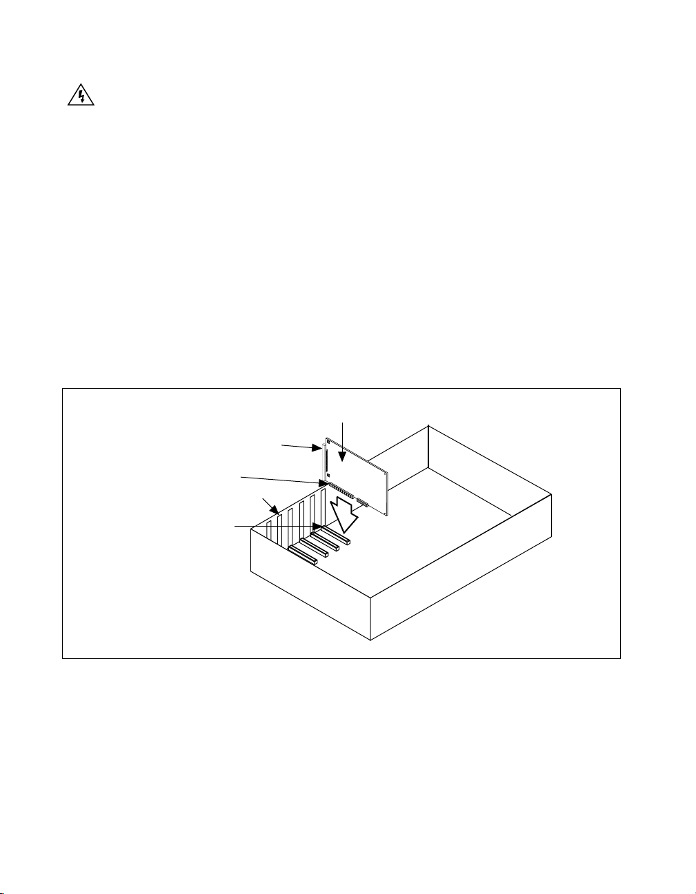
5. Line up the PCI-MXI-2 with the MXI-2 connector near the cut-out on
the back panel. Slowly push down on the top of the PCI-MXI-2 until
its card-edge connector is resting on the expansion slot receptacle.
Using slow , e v enly distributed pressure, press the PCI-MXI-2 straight
down until it seats in the expansion slot.
6. Check the installation. Ensure that the PCI-MXI-2 is secure in its slot.
7. Replace the computer cover.
Figure 2-2 shows how to install the PCI-MXI-2.
PCI-MXI-2 Board
MXI-2 Connector
PCI Bus
Card-Edge Connector
Cut-outs
PCI Bus Slot
Figure 2-2. PCI-MXI-2 Installed in a Computer
VXI/VME-PCI8026 for Linux 2-4 www.ni.com
Page 33

VXI-MXI-2 Configuration
and Installation
This chapter contains the instructions to configure and install the
VXI-MXI-2 module. This chapter applies only if you ordered the
VXI-PCI8026 interface kit. If you ordered the VME-PCI8026 kit,
skip this chapter and ref er to Chapter 4, VME-MXI-2 Configuration
and Installation.
3
Caution
module. T o avoid such damage in handling the module, touch the antistatic plastic package
to a metal part of your VXI chassis before removing the VXI-MXI-2 from the package.
Electrostatic discharge can damage several components on your VXI-MXI-2
Configure the VXI-MXI-2
This section describes how to configure the following options on the
VXI-MXI-2:
• VXIbus logical address
• VXIbus Slot 0/Non-Slot 0
• VXIbus local bu s
• VXIbus CLK10 routing
• Trigger input termination
• MXIbus termination
• Configuration EEPROM
• On board DRAM
Note
If you have only one VXI chassis in your system, you should leave the VXI-MXI-2
at Logical Address 1 and install it into Slot 0. To install the VXI-MXI-2, see Install the
VXI-MXI-2 later in this chapter.
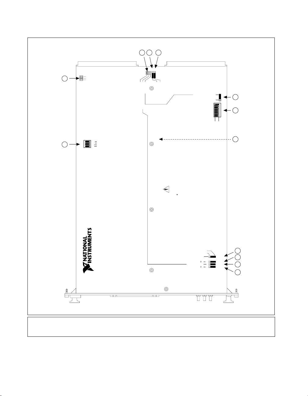
Figure 3-1 shows the VXI-MXI-2 as it would appear when facing the right
side cover. The drawing shows the location and factory-default settings of
most of the configuration switches and jumpers on the module. Notice that
switch S6 is accessible only by removing the front cover.
© National Instruments Corporation 3-1 VXI/VME-PCI8026 for Linux
Page 34
Chapter 3 VXI-MXI-2 Configuration and Installation
Nonslot 0
Auto
2
1
Slot 0
W2
No
Yes
1
No
Yes
Yes
432
U35
Terminate MXIbus
Yes
No
No
Automatic MXIbus Termination
Change Factory Configuration
Restore Factory Configuration
3 4 5
S8
S9
W3
CLK10
Source
From MXIbus
From onboard oscillator
From SMB (S3 must be set to "IN")
YesNo
VXI-MXI to left
VXI-MXI to right
Routing
MXI CLK10
Turn off power to instruments and cables
before installing or removing any modules.
WARNING:
SWITCH
Shown at default
Address 1
setting of Logical
LOGICAL ADDRESS
Receive CLK10 from MXIbus
S7
Drive CLK10 out MXIbus
87
654
U43
3
21
Push up for logic 1
Push down for logic 0
6
7
8
(All switches and jumpers shown in default position)
VXI-MXI-2
INVERTED
NON-INVERTED
SMB CLK10 Output Polarity (Effective only when S3 is set to "OUT")
50 Termination for SMB CLK10 (Effective only when S3 is set to "IN")
On
In
SMB CLK10 Direction
On
50 Termination for External Trigger Input
9
S5
10
S4 Off
S3
Out
11
S2 Off
12
1U35
2W2
3W3
4S8
5S9
6S7
7U43
8S6
9S5
10 S4
11 S3
12 S2
Figure 3-1. VXI-MXI-2 Right-Side Cover
VXI/VME-PCI8026 for Linux 3-2 www.ni.com
Page 35

Front Panel Features
The VXI-MXI-2 has the following front panel features:
• Three front panel LEDs
– SYSFAIL LED indicates that the VMEbus SYSFAIL line is
asserted.
– MXI LED indicates when the VXI-MXI-2 is accessed from the
MXIbus.
– VXI LED indicates when the VXI-MXI-2 is accessed from the
VXIbus.
• MXIbus connector
• Three SMB connectors
– External clock
– Trigger output
– Trigger input
• System reset push-button
Removing the Metal Enclosure
The VXI-MXI-2 is housed in a metal enclosure to improve EMC
performance and to provide easy handling. Because the enclosure includes
cutouts to facilitate changes to the switch and jumper settings, it should not
be necessary to remove it under normal circumstances.
Chapter 3 VXI-MXI-2 Configuration and Installation
However, it is necessary to remove the enclosure if you want to change
the amount of DRAM installed on the VXI-MXI-2. Swit ch S6, which is
directly related to the amount of DRAM you want to install, is also
accessible only by removing the enclosure. If you will be making this
change, remove the four screws on the top, the four screws on the bottom,
and the five screws on the right side cover of the enclosure. Refer to the
Onboard DRAM section later in this chapter for details about changing
DRAM.
VXIbus Logical Address
Each device in a VXIbus/MXIbus system is assigned a unique number
between 0 and 254. This 8-bit number, called the logical address, defines
the base address for the VXI configuration registers located on the device.
With unique logical addresses, each VXIbus device in the system is
assigned 64 bytes of configuration space in the upper 16 KB of A16 space.
© National Instruments Corporation 3-3 VXI/VME-PCI8026 for Linux
Page 36

Chapter 3 VXI-MXI-2 Configuration and Installation
Logical address 0 is reserved for the Resource Manager in the VXIbus
system. Because the VXI-MXI-2 cannot act as a Resource Manager, do not
configure the VXI-MXI-2 with a logical address of 0.
Some VXIbus devices have dynamically configurable logical addresses.
These devices have an initial logical address of hex FF or 255, which
indicates that they can be dynamically configured. While the VXI-MXI-2
does support dynamic configuration of VXI devices within its mainframe,
it is itself a statically configured device and is preset at the factory with a
VXI logical address of 1.
Ensure that no other statically configurable VXIbus devices have a
logicaladdress of 1. If they do, change the logical address setting of either
the VXI-MXI-2 or the other device so that every device in the system has a
unique associated logical address.
You can change the logical address of the VXI-MXI-2 by changing the
setting of the 8-bit DIP switch labeled LOGICAL ADDRESS SWITCH
(location designator U43) on the panel. The down position of the DIP
switch corresponds to a logic value of 0 and the up position corresponds
to a logic value of 1. Verify that the VXI-MXI-2 does not have the same
logical address as any other statically configured VXIbus device in your
system. Remember that logical addresses hex 0 and FF are not allowed for
the VXI-MXI-2. Also, when setting logical addresses, keep in mind the
grouping requirements set by the system hierarchy. See VXI-6, VXIbus
Mainframe Extender Specification, for more information on setting logical
addresses on a multimainframe hierarchy.
VXI/VME-PCI8026 for Linux 3-4 www.ni.com
Page 37
Chapter 3 VXI-MXI-2 Configuration and Installation
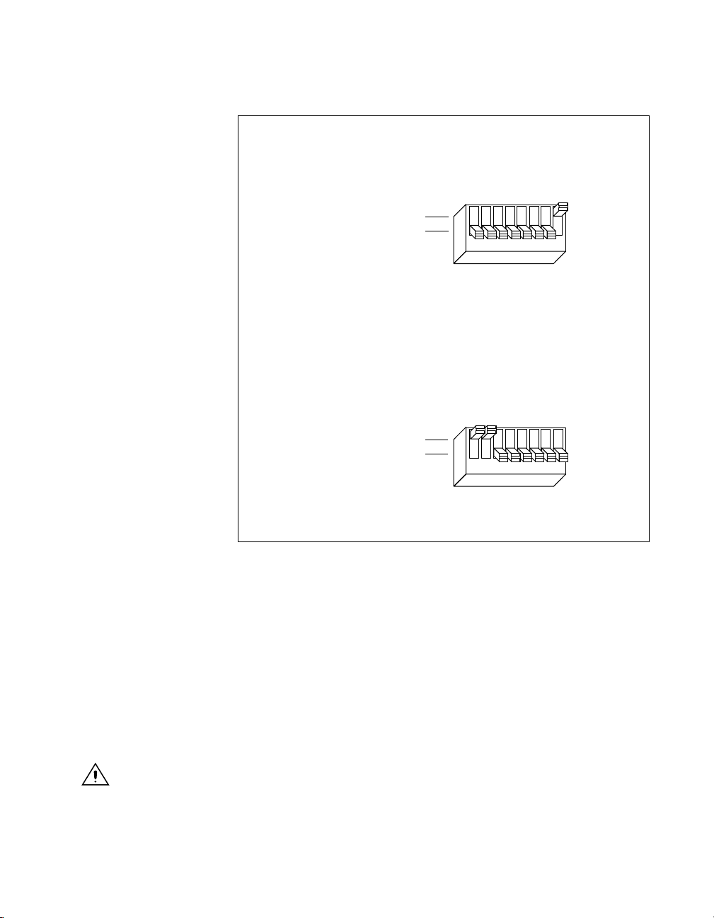
Figure 3-2 shows switch settings for logical address hex 1 and C0.
LOGICAL ADDRESS
SWITCH
Shown at
default setting of
Logical Address 1
Push up for logic 1
Push down for logic 0
a. Switch Set to Logical Address 1 (Default)
Push up for logic 1
Push down for logic 0
12345678
U43
LOGICAL ADDRESS
SWITCH
Shown at
default setting of
Logical Address 1
12345678
U43
b. Switch Set to Logical Address Hex C0
Figure 3-2.
Logical Address Selection
VXIbus Slot 0/Non-Slot 0
The VXI-MXI-2 is configured at the factory to automatically detect if it is
installed in Slot 0 of a VXIbus mainframe. With automatic Slot 0 detection,
you can install the VXI-MXI-2 into any VXIbus slot.
You can manually configure the VXI-MXI-2 for either Slot 0 or
Non-Slot 0 operation by defeating the automatic-detection circuitry. Use
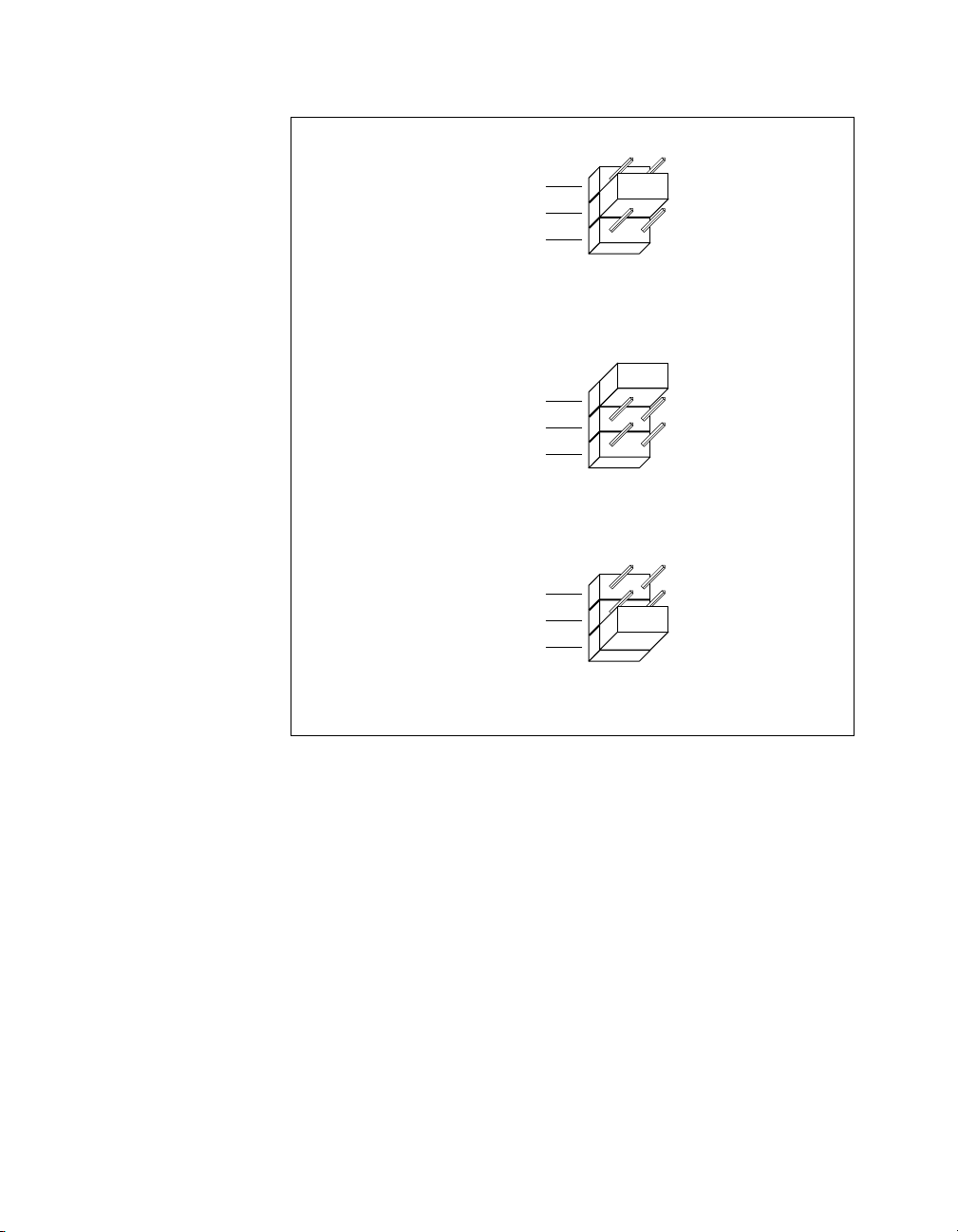
the three-position jumper W2 to select automatic Slot 0 detection, Slot 0,
or Non-Slot 0 operation. Figure 3-3 shows these three settings.
Caution
reconfiguring it to either Non-Slot 0 or automatic configuration. Neglecting to do this
could damage the device, the VXIbus backplane, or both.
© National Instruments Corporation 3-5 VXI/VME-PCI8026 for Linux
Do not install a device configured for Slot 0 into another slot without first
Page 38
Chapter 3 VXI-MXI-2 Configuration and Installation
W2
Slot 0
Auto
Nonslot 0
a. Automatic Slot 0 Detection (Default)
W2
Slot 0
Auto
Nonslot 0
b. Manual Slot 0 Configuration
W2
Slot 0
Auto
Nonslot 0
c. Manual Nonslot 0 Configuration
Figure 3-3. VXIbus Slot Configuration
When the VXI-MXI-2 is installed in Slot 0, it becomes the VMEbus
System Controller. In this role, it has VMEbus Data Transfer Bus Arbiter
circuitry that accepts bus requests on all four VMEbus request levels,
prioritizes the requests, and grants the bus to the highest priority requester.
As VMEbus System Controller, the VXI-MXI-2 also drives the 16 MHz
VMEbus system clock by an onboard 16 MHz oscillator.
As required by the VXIbus specification, the VXI-MXI-2 drives the
10 MHz signal CLK10 on a differential ECL output when installed in
Slot 0. When not installed in Slot 0, the VXI-MXI-2 only receives the
CLK10 signal.
VXI/VME-PCI8026 for Linux 3-6 www.ni.com
Page 39

VXIbus Local Bus
Chapter 3 VXI-MXI-2 Configuration and Installation
If you will be installing more than one VXI-MXI-2 in a single VXIbus
mainframe, you must configure the boards to use the local bus. The
VXI-MXI-2 uses the local bus to pass a signal to the other VXI-MXI-2
modules in the mainframe to disable the VMEbus bus timeout unit (BTO)
during cycles that map to the MXIbus. Because the local bus is used,
you need to install all VXI-MXI-2 modules for a single m ainf ram e in
adjacent slots.
You will use two switches on the VXI-MXI-2 to select its position in
relation to any other VXI-MXI-2 module in the mainframe. Use switch S9
when there is a VXI-MXI-2 to the right (higher numbered slot). Use S8
when there is a VXI-MXI-2 to the left (lower numbered slot).
Figure 3-4 shows four configuration settings for a VXI-MXI-2. Figure 3-4a
illustrates the default setting, which is for a single VXI-MXI-2 in a
mainframe. Use the setting in Figure 3-4b for the VXI-MXI-2 located to
the left of all others. Figure 3-4c shows the setting to use if the VXI-MXI-2
is between two others. Use the setting of Figure 3-4d for the VXI-MXI-2
located to the right of all others.
© National Instruments Corporation 3-7 VXI/VME-PCI8026 for Linux
Page 40
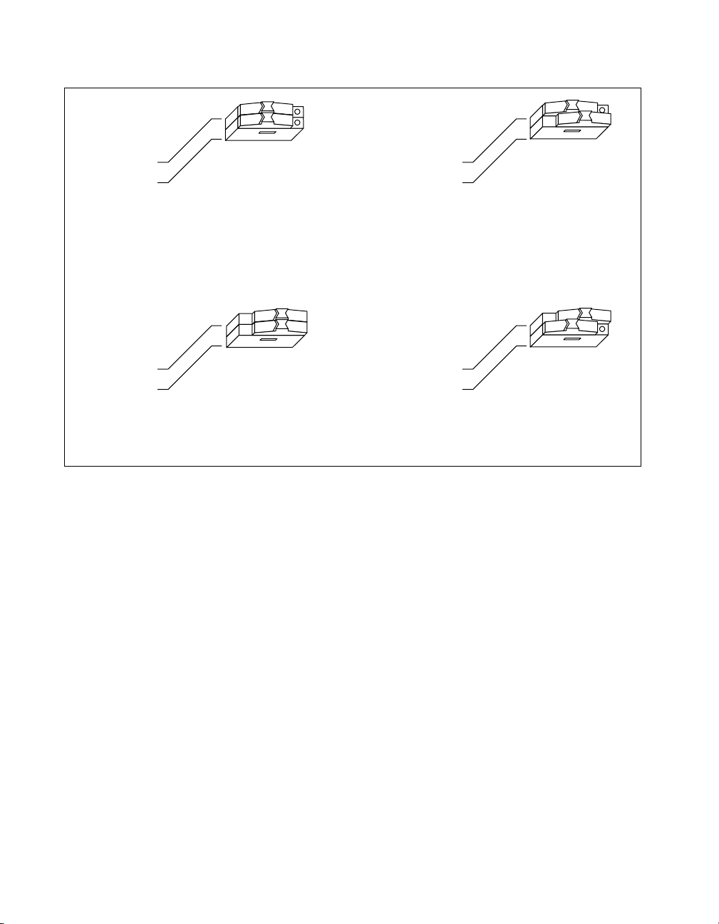
Chapter 3 VXI-MXI-2 Configuration and Installation
VXI-MXI to left
No Yes
VXI-MXI to right
a. Single VXI-MXI-2 in Mainframe (Default)
No Yes
VXI-MXI to left
VXI-MXI to right
c.VXI-MXI-2 between Two Others
VXIbus CLK10 Routing
When the VXI-MXI-2 is installed in Slot 0 of your mainframe, it supplies
the VXIbus CLK10 signal. The VXI-MXI-2 can use three different sources
to generate this signal: an onboard oscillator, the external CLK SMB
connector, and the MXIbus CLK10 signal. Use the three-position jumper
W3 to select these options, as shown in Figure 3-5.
S8
S9
VXI-MXI to left
VXI-MXI to right
b. Leftmost VXI-MXI-2 in Mainframe
S8
S9
VXI-MXI to left
VXI-MXI to right
d. Rightmost VXI-MXI-2 in Mainframe
Figure 3-4. VXIbus Local Bus Configuration
S8
S9
No Yes
S8
S9
No Yes
Notice that Figure 3-5b and Figure 3-5c also show switches S3 and S7,
respectively. You must configure these switches as shown when using the
corresponding CLK10 source setting of W3.
VXI/VME-PCI8026 for Linux 3-8 www.ni.com
Page 41
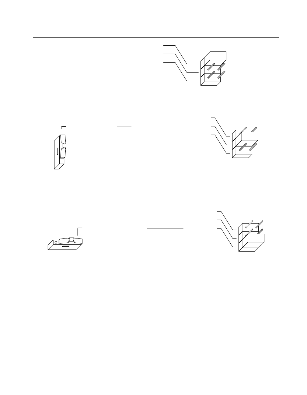
Chapter 3 VXI-MXI-2 Configuration and Installation
In
S3 Out
From onboard oscillator
From SMB (S3 must be set to “IN”)
From MXIbus
a. CLK10 Generated from Onboard Oscillator (Default)
From onboard oscillator
From SMB (S3 must be set to “IN”)SMB CLK10 Direction
From MXIbus
b. CLK10 Generated from SMB
From onboard oscillator
From SMB (S3 must be set to “IN”)
From MXIbusReceive CLK10 from MXIbus
W3
W3
W3
S7
c. CLK10 Generated from MXIbus
Figure 3-5.
VXIbus CLK10 Routing
The VXI-MXI-2 can also be configured to drive the external CLK SMB
signal from the VXIbus CLK10 signal. Switch S3 controls whether the
VXI-MXI-2 drives or receiv es the external CLK SMB signal. If you change
the S3 setting to drive CLK10 out the external CLK10 SMB connector, do
not set the W3 jumper to receive the SMB CLK10 signal; instead use the
settings shown in either Figure 3-5a or Figure 3-5c as appropriate.
When switch S3 is set so that the VXI-MXI-2 receives the SMB CLK10
signal, you have the option to add a 50 is unused—its setting does not
matter—when S3 is configured to drive the external CLK SMB signal.
© National Instruments Corporation 3-9 VXI/VME-PCI8026 for Linux
Page 42

Chapter 3 VXI-MXI-2 Configuration and Installation
You can use an additional switch, S5, to control the polarity of the external
CLK SMB signal when S3 is configured to drive it. S5 is unused—its
setting does not matter—when S3 is configured to receive the external CLK
SMB signal.
Figure 3-6 shows four configuration settings for the VXI-MXI-2.
Figure 3-6a shows the default configuration, which is for driving the
inverted external CLK SMB. Use the settings of Figure 3-6b to drive the
noninverted external CLK SMB signal. Figure 3-6c illustrates the setting
for receiving the external CLK SMB signal. Finally , you can conf igure the
switches as shown in Figure 3-6d to receive the external CLK SMB signal
with a 50 Ω termination.
Note
The settings of any switches shown with this pattern ( ) have no bearing on the
configuration described in any of the following figures.
VXI/VME-PCI8026 for Linux 3-10 www.ni.com
Page 43
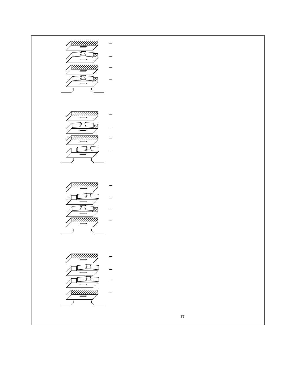
Chapter 3 VXI-MXI-2 Configuration and Installation
S2 Off
S3 Out
S4 Off
S5
INVERTED
S2 Off
S3 Out
S4 Off
S5
S2 Off
S3 Out
S4 Off
S5
On 50 Termination for External Trigger Input
In
SMB CLK10 Direction
50 Termination for SMB CLK10 (Effective only when S3 is set to “IN”)
On
SMB CLK10 Output Polarity (Effective only when S3 is set to “OUT”)
NON-INVERTED
a. Drive Inverted External CLK SMB (Default)
On 50W Termination for External Trigger Input
In
SMB CLK10 Direction
50W Termination for SMB CLK10 (Effective only when S3 is set to “IN”)
On
SMB CLK10 Output Polarity (Effective only when S3 is set to “OUT”)
NON-INVERTEDINVERTED
b. Drive Non-Inverted External CLK SMB
On 50W Termination for External Trigger Input
In
SMB CLK10 Direction
50W Termination for SMB CLK10 (Effective only when S3 is set to “IN”)
On
SMB CLK10 Output Polarity (Effective only when S3 is set to “OUT”)
NON-INVERTEDINVERTED
c. Receive External CLK SMB
S2 Off
S3 Out
S4 Off
S5
© National Instruments Corporation 3-11 VXI/VME-PCI8026 for Linux
On 50W Termination for External Trigger Input
In
SMB CLK10 Direction
50W Termination for SMB CLK10 (Effective only when S3 is set to “IN”)
On
SMB CLK10 Output Polarity (Effective only when S3 is set to “OUT” )
NON-INVERTEDINVERTED
d. Receive External CLK SMB with 50 Termination
Figure 3-6.
SMB CLK10 Settings
Page 44
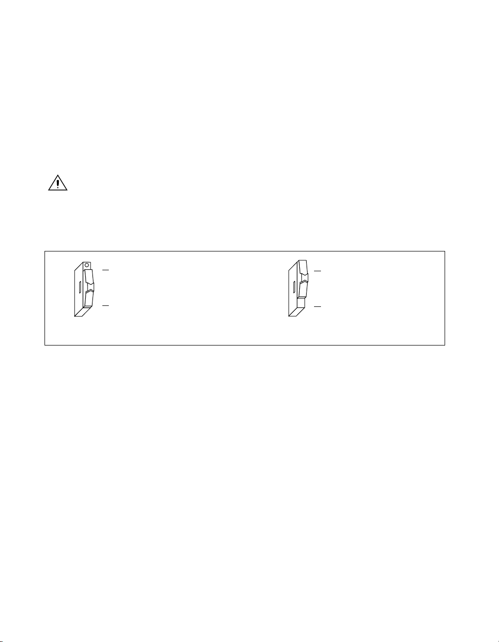
Chapter 3 VXI-MXI-2 Configuration and Installation
The VXI-MXI-2 can also drive or receive the MXIbus CLK10 signal.
Switch S7 controls whether the VXI-MXI-2 drives MXIbus CLK10 from
the VXIbus CLK10 or receives MXIbus CLK10. As shown earlier in
Figure 3-5c, if W3 is configured to use the MXIbus CLK10 to generate the
VXIbus CLK10 signal, switch S7 must be configured to receive MXIbus
CLK10. This is shown again in Figure 3-7a below. If you change the
S7 setting to drive CLK10 out the MXIbus, do not set the W3 jumper to
receive the MXIbus CLK10; instead use the settings shown in Figure 3-5a
or Figure 3-5b as appropriate.
Caution
Do not configure more than one MXIbus device to drive the MXIbus CLK10.
Having a second device driving MXIbus CLK10 could damage the device.
Figure 3-7 shows the configuration settings for receiving and driving
MXIbus CLK10, respectively.
Drive CLK10 out MXIbus
S7
Receive CLK10 from MXIbus
a. Receive CLK10 from MXIbus (Default) b. Drive MXIbus CLK10 from VXIbus CLK10
Figure 3-7. Receiving or Driving MXIbus CLK10
S7
Drive CLK10 out MXIbus
Receive CLK10 from MXIbus
Trigger Input Termination
You can use switch S2 to terminate the external trigger input SMB with
50 Ω. Figure 3-8a shows the default setti ng for a nont erminated trigger
input SMB. Use the setting of Figure 3-8b to termi nate the trigger input
SMB. Switch S2 is located above switches S3, S4, and S5, which have no
effect on this configuration.
VXI/VME-PCI8026 for Linux 3-12 www.ni.com
Page 45
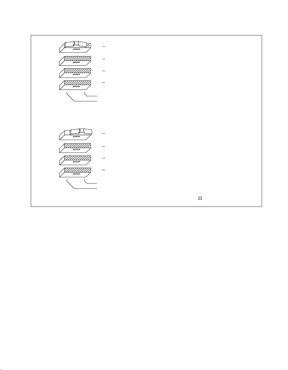
Chapter 3 VXI-MXI-2 Configuration and Installation
)
S2 Off
S3 Out
S4 Off
S5
S2 Off
S3 Out
S4 Off
S5
On 50W Termination for External Trigger Input
In
SMB CLK10 Direction
50W Termination for SMB CLK10 (Effective only when S3 is set to “IN”
On
SMB CLK10 Output Polarity (Effective only when S3 is set to “OUT”)
NON-INVERTED
INVERTED
a. Non-Terminated External Trigger Input SMB (Default)
On 50W Termination for External Trigger Input
In
SMB CLK10 Direction
50W Termination for SMB CLK10 (Effective only when S3 is set to “IN”
On
SMB CLK10 Output Polarity (Effective only when S3 is set to “OUT”)
NON-INVERTED
INVERTED
b. Terminated External Trigger Input SMB with 50
Figure 3-8.
SMB Trigger Input Termination
MXIbus Termination
The first and last MXIbus devices connected to the MXIbus—whether it is
a single MXI-2 cable or daisy-chained MXI-2 cables—must terminate the
MXIbus. Any MXIbus devices in the middle of a MXIbus daisy chain must
not terminate the MXIbus.
The VXI-MXI-2 automatically senses whether it is at either end of the
MXIbus cable to terminate the MXIbus. You can manually control MXIbus
termination by defeating the automatic circuitry. Use switches 1 and 2
of the four-position switch at location U35 to control whether MXIbus
termination is automatic (Figure 3-9a) , on ( Figure 3-9b), or off
(Figure 3-9c). The settings of switches 3 and 4 have no effect on MXIbus
termination.
© National Instruments Corporation 3-13 VXI/VME-PCI8026 for Linux
Page 46
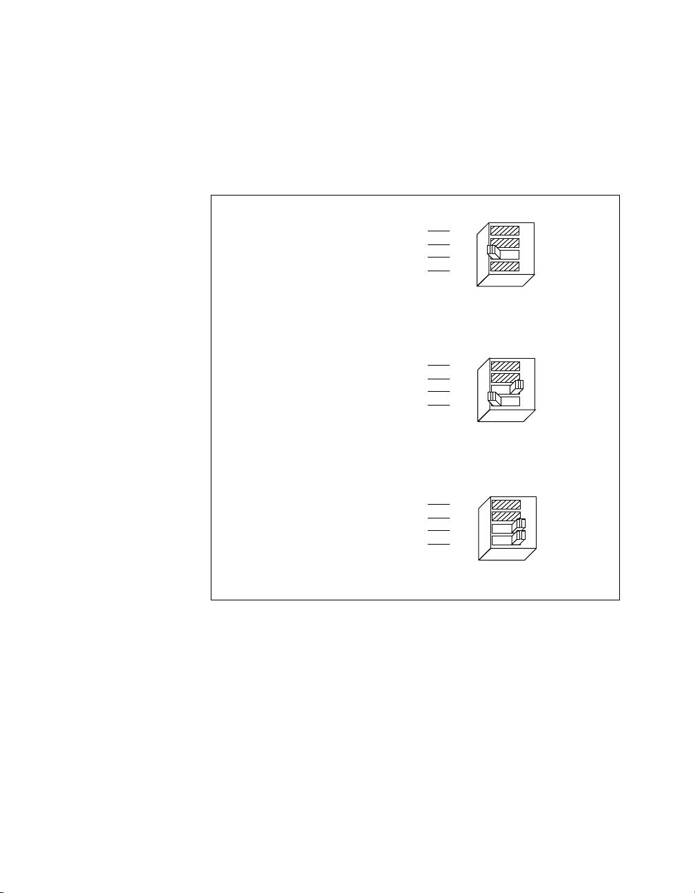
Chapter 3 VXI-MXI-2 Configuration and Installation
Use switch 2 of U35 to select whether you want the VXI-MXI-2 to
automatically control termination of the MXIbus. Switch 1 of U35 lets
you manually control whether to terminate the MXIbus when automatic
termination is turned off. Switch 1 has no effect when switch 2 is set for
automatic MXIbus termination; you must turn off automatic termination if
you want to manually control termination.
Restore Factory Configuration
Change Factory Configuration
Automatic MXIbus Termination
Restore Factory Configuration
Change Factory Configuration
Automatic MXIbus Termination
U35
No
No
Terminate MXIbus
a. Automatic MXIbus Termination (Default)
Terminate MXIbus
Yes
Yes
U35
No
No
Yes
Yes
Yes
Yes
No
1234
No
Yes
Yes
No
1234
No
b. Terminate MXIbus (On)
Restore Factory Configuration
Change Factory Configuration
Automatic MXIbus Termination
Terminate MXIbus
c. Do Not Terminate MXIbus (Off)
Figure 3-9. MXIbus Termination
No
No
Yes
Yes
U35
Yes
Yes
No
1234
No
VXI/VME-PCI8026 for Linux 3-14 www.ni.com
Page 47

Configuration EEPROM
The VXI-MXI-2 has an onboard EEPROM, which stores default register
values that are loaded at power-on. The EEPROM is divided into two
halves—a factory-configuration half, and a user-configuration half. Both
halves were factory configured with the same configuration values so you
can modify the user-configurable half, while the factory-configured half
stores a back-up of the default user settings.
Use switches 3 and 4 of the four-position switch at location U35 to control
the operation of the EEPROM. The Restore Factory Configuration switch
(switch 4) causes the VXI-MXI-2 to boot off the factory-configured half
instead of the user-modified settings. This is useful in the event that the
user-configured half of the EEPR OM becomes corrupted in such a way that
the VXI-MXI-2 boots to an unusable state.
The Change Factory Configuration switch (switch 3 of U35) lets you
change the factory-default configuration settings by permitting writes to the
factory settings section of the EEPROM. This switch serves as a safety
measure and should not be needed under normal circumstances. When this
switch is off (its default setting) the factory configuration of the EEPROM
is protected, so any writes to the factory area will be ignored. The factory
area is protected regardless of the setting of switch 4 of U35.
Chapter 3 VXI-MXI-2 Configuration and Installation
Figure 3-10 shows the configuration settings for EEPROM operation. The
settings of switches 1 and 2 have no effect on EEPROM configuration.
© National Instruments Corporation 3-15 VXI/VME-PCI8026 for Linux
Page 48
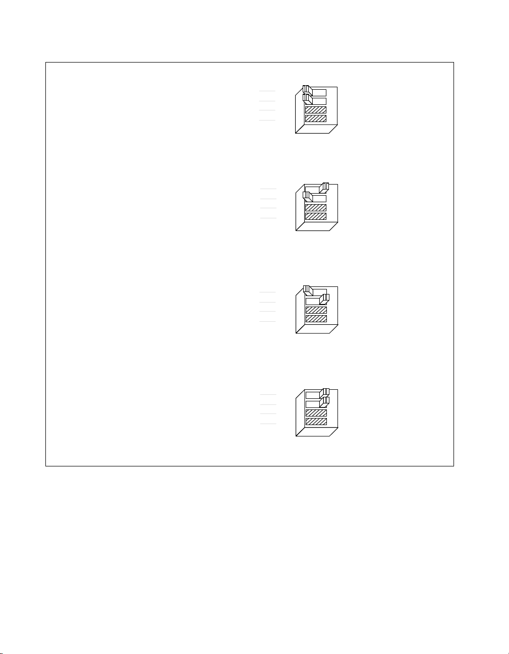
Chapter 3 VXI-MXI-2 Configuration and Installation
Restore Factory Configuration
Change Factory Configuration
Automatic MXIbus Termination
Terminate MXIbus
a. Boot from User Configuration (Factory Configuration Protected) (Default)
Restore Factory Configuration
Change Factory Configuration
Automatic MXIbus Termination
Terminate MXIbus
b. Boot from Factory Configuration (Factory Configuration Protected)
Restore Factory Configuration
Change Factory Configuration
Automatic MXIbus Termination
Terminate MXIbus
No
No
Yes
Yes
No
No
Yes
Yes
No
No
Yes
Yes
U35
U35
U35
Yes
Yes
No
1234
No
Yes
Yes
No
1234
No
Yes
Yes
No
1234
No
c. Boot from User Configuration (Factory Configuration Unprotected)
U35
Restore Factory Configuration
Change Factory Configuration
Automatic MXIbus Termination
Terminate MXIbus
No
No
Yes
Yes
Yes
Yes
No
1234
No
d. Boot from Factory Configuration (Factory Configuration Unprotected)
Figure 3-10. EEPROM Operation
VXI/VME-PCI8026 for Linux 3-16 www.ni.com
Page 49

Onboard DRAM
Chapter 3 VXI-MXI-2 Configuration and Installation
The VXI-MXI-2 can accommodate up to two 1.35 in. DRAM SIMMs.
Table 3-1 lists the SIMMs you can use.
Table 3-1.
VXI-MXI-2 DRAM Configurations
National
Instruments
Bank 0 Bank 1 Total DRAM
Option?
— — 0 — —
256 K × 32 or
— 1 MB — ON
256 K × 36
256 K × 32 or
256 K × 36
512 K × 32 or
256 K × 32 or
2 MB — ON
256 K × 36
— 2 MB — ON
512 K × 36
512 K × 32 or
512 K × 36
1 M × 32 or
512 K × 32 or
4 MB — ON
512 K × 36
— 4 MB YES ON
1M× 36
1 M × 32 or
1M× 36
2 M × 32 or
1 M × 32 or
8 MB — ON
1M× 36
— 8 MB YES ON
2M× 36
Switch Setting
of S6
2 M × 32 or
2M× 36
4 M × 32 or
2 M × 32 or
16 MB — ON
2M× 36
— 16 MB YES OFF
4M× 36
4 M × 32 or
4M× 36
8 M × 32 or
4 M × 32 or
32 MB — OFF
4M× 36
— 32 MB YES OFF
8M× 36
8 M × 32 or
8M× 36
© National Instruments Corporation 3-17 VXI/VME-PCI8026 for Linux
8 M × 32 or
8M× 36
64 MB YES OFF
Page 50
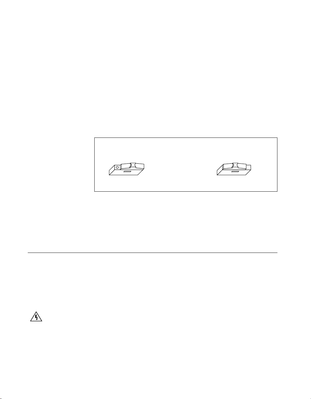
Chapter 3 VXI-MXI-2 Configuration and Installation
You can use 32-bit or 36-bit SIMMs because DRAM parity is not required.
Because the VXI-MXI-2 supports only one organization at a time, all
SIMMs installed must be of the same type. Use Bank 0 first when installing
the SIMMs. This allows you to install up to 64 MB. The VXI-MXI-2
supports DRAM speeds of 80 ns or faster.
Switch S6 is used to select the size of each SIMM. The SIMM sockets and
S6 are accessible only by removing the right-side cover. To access these
components, remove the four screws on the top, the four screws on the
bottom, and the five screws on the right-side cover of the metal enclosure.
If the SIMMs are 4 M × 32 or larger, S6 should be in the OFF setting as
shown in Figure 3-11a. For SIMMs smaller than 4 M × 32, use the ON
setting as shown in Figure 3-11b.
Refer to Table 3-1 for how to adjust the switch (ON or OFF) for all
supported DRAM configurations. Many of the DRAM options are
available from National Instruments.
Install the VXI-MXI-2
This section contains general installation instructions for the VXI-MXI-2.
Consult your VXIbus mainframe user manual or technical reference
manual for specific instructions and warnings.
1. Plug in your mainframe before installing the VXI-MXI-2. The power
cord grounds the mainframe and protects it from electrical damage
while you are installing the module.
Warning
mainframe should remain off until you are finished installing the VXI-MXI-2 module.
To protect both yourself and the mainframe from electrical hazards, the
SIMM Size
(• = 4M x 32
and Larger)
S6
b. Smaller than 4 M x 32a. 4 M x 32 and Larger
Figure 3-11. SIMM Size Configuration
SIMM Size
(• = 4M x 32
and Larger)
S6
2. Remove or open any doors or covers blocking access to the
mainframe slots.
VXI/VME-PCI8026 for Linux 3-18 www.ni.com
Page 51

Chapter 3 VXI-MXI-2 Configuration and Installation
3. If you are installing the VXI-MXI-2 into a D-size mainframe, install a
support designed for installing C-size boards in D-size mainframes.
The VXI-MXI-2 has no P3 connector and cannot provide P3 Slot 0
control to VXI devices requiring this capability.
Caution
the slot you select in your VXIbus mainframe matches the VXI-MXI-2 configuration as
either a Slot 0 device or a Non-Slot 0 device. If you install your VXI-MXI-2 into a slot that
does not correspond with the jumper setting, you risk damage to the VXI-MXI-2, the
VXIbus backplane, or both.
If the VXI-MXI-2 is not configured for automatic Slot 0 detection, be certain that
4. Insert the VXI-MXI-2 in the slot you have selected by aligning the
top and bottom of the board with the card-edge guides inside the
mainframe. Slowly push the VXI-MXI-2 straight into the slot until its
plug connectors are resting on the backplane receptacle connectors.
Using slow , e venly distributed pressure, press the VXI-MXI-2 straight
in until it seats in the expansion slot. The front panel of the VXI-MXI-2
should be even with the front panel of the mainframe.
5. Tighten the retaining screws on the top and bottom edges of the
front panel.
6. Check the installation.
7. Connect the cables as described in the following section before
restoring power.
8. Replace or close any doors or covers to the mainframe.
Connect the MXIbus Cable
There are two basic types of MXI-2 cables. MXI-2 cables can have either
a single connector on each end or a single connector on one end and a
double connector on the other end.
Connect the labeled end of the cable to the MXI-2 device that will be the
MXIbus System Controller . Connect the other end of the cable to the other
device. Be sure to tighten the screw locks to ensure proper pin connection.
Figure 3-12 shows the correct cabling for a VXI system containing a
PCI-MXI-2 board in a PCI-based computer cabled to a VXI-MXI-2 module
residing in Slot 0 of a VXIbus mainframe. Notice that you can expand your
system to include other devices by using an additional MXI-2 cable.
However , in such a case the f irst cable needs to have a double connector on
one end. Y ou can use a cable with a single connector on each end to connect
the last device on the MXIbus.
© National Instruments Corporation 3-19 VXI/VME-PCI8026 for Linux
Page 52
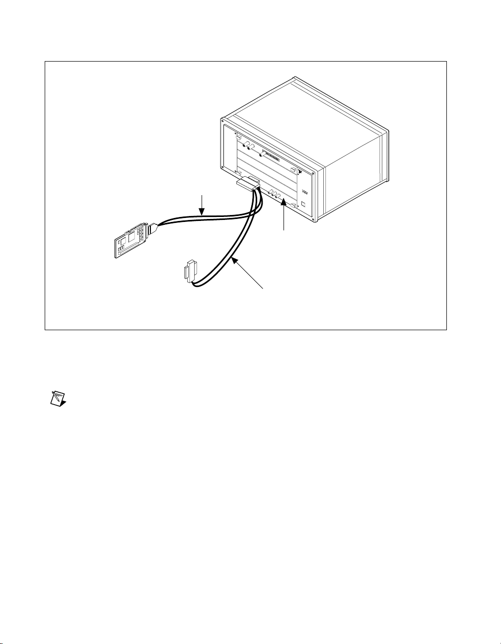
Chapter 3 VXI-MXI-2 Configuration and Installation
VXI Mainframe
MXI-2 Cable
PCI-MXI-2
Interface Module
To External
Computer
N
A
I
T
N
I
S
O
T
N
R
A
U
L
M
E
N
b
u
s
VXI-MXI-2 Slot 0
Module
T
S
®
To Other
Mainframes
Additional MXI-2 Cable
(Ordered Separately)
Figure 3-12. MXI-2 Cable Configuration Using a PCI-MXI-2 and a VXI-MXI-2
When you have properly connected the MXI-2 cable, power on the VXIbus
mainframe and then the computer.
Note
Always turn on the mainframe first. Doing so makes it possible for your external
computer to access the VXI boards in the mainframe upon startup.
VXI/VME-PCI8026 for Linux 3-20 www.ni.com
Page 53

VME-MXI-2 Configuration
and Installation
This chapter contains the instructions to configure and install the
VME-MXI-2 module. This chapter applies only if you ordered the
VME-PCI8026 interface kit. If you ordered the VXI-PCI8026 kit, you
should refer to Chapter 3, VXI-MXI-2 Configuration and Installation.
4
Caution
module. T o avoid such damage in handling the module, touch the antistatic plastic package
to a metal part of your VMEbus chassis before removing the VME-MXI-2 from the
package.
Electrostatic discharge can damage several components on your VME-MXI-2
Configure the VME-MXI-2
This section describes how to configure the following options on the
VME-MXI-2:
• VMEbus A16 base address
• VME-MXI-2 intermodule signaling
• MXIbus termination
• Configuration EEPROM
• Onboard DRAM
The VME-MXI-2 automatically detects if it is located in the first slot of
the chassis to perform the VMEbus System Controller functions. It is not
necessary to configure the VME-MXI-2 System Controller option. The
module can be installed in any slot of a VMEbus chassis.
Figure 4-1 shows the VME-MXI-2. The drawing shows the location and
factory-default settings of the configuration switches and jumpers on the
module.
© National Instruments Corporation 4-1 VXI/VME-PCI8026 for Linux
Page 54
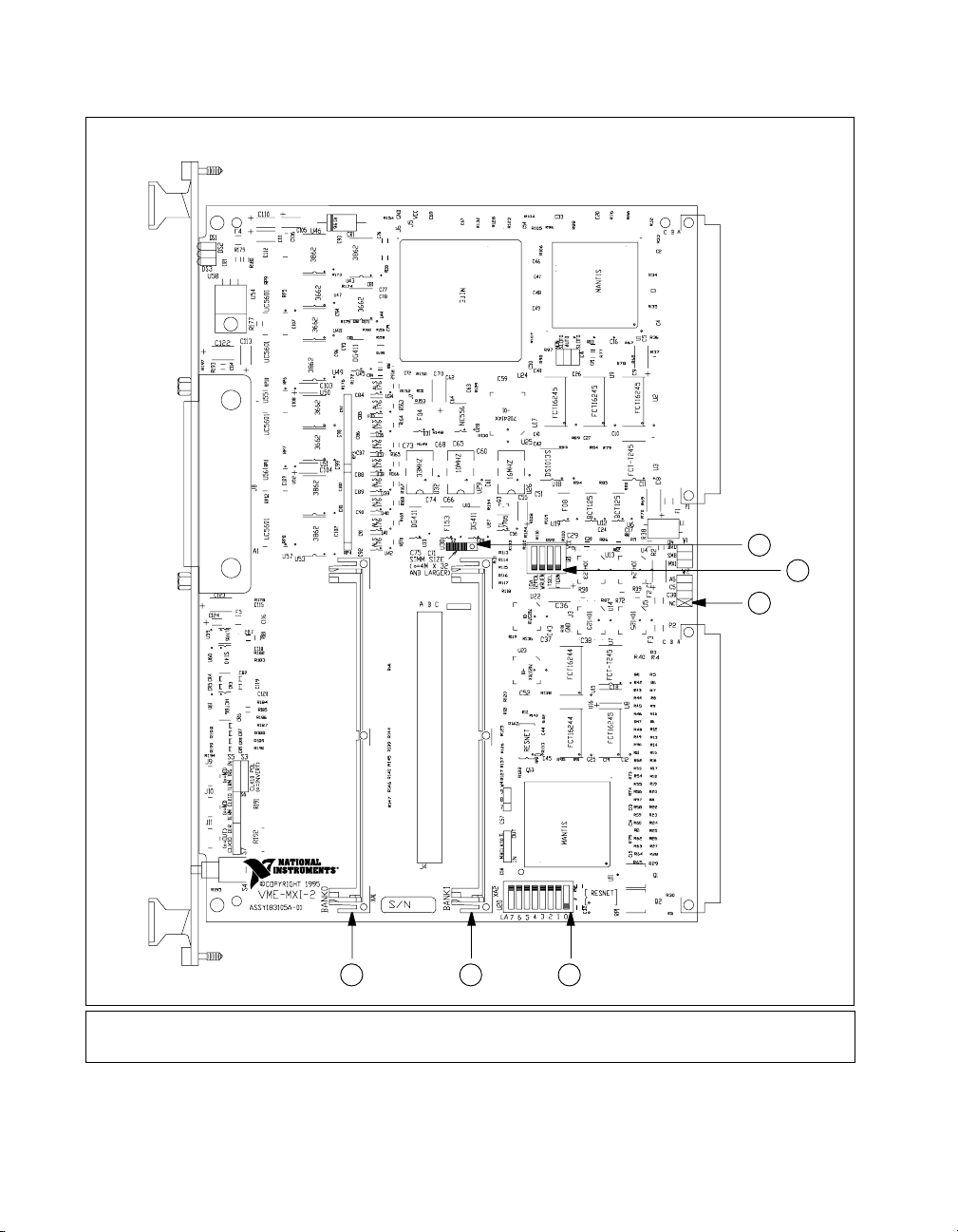
Chapter 4 VME-MXI-2 Configuration and Installation
1
2
3
5 4
5 DRAM Bank 1
6 DRAM Bank 0
1S2
2U21
6
3W2
4U20
Figure 4-1. VME-MXI-2 Parts Locator Diagram
VXI/VME-PCI8026 for Linux 4-2 www.ni.com
Page 55

Front Panel Features
The VME-MXI-2 has the following front panel features:
• Three front panel LEDs
– SYSFAIL LED indicates that the VMEbus SYSFAIL line is
– MXI LED indicates when the VME-MXI-2 is accessed from
– VME LED indicates when the VME-MXI-2 is accessed from
• MXIbus connector
• System reset push-button
VMEbus A16 Base Address
The VME-MXI-2 requires 64 bytes of A16 space for its configuration
registers. It uses the logical address scheme of the VXIbus specification,
in which each device is assigned an 8-bit value called the logical address.
This logical address allocates 64 bytes of space to the device within the
upper quarter of A16 space. The VME-MXI-2 cannot be configured to
locate its registers in the lower three quarters of A16 space. The A16 base
address of the VME-MXI-2 will be address lines 15 and 14 high with
address lines 13 through 6 matching the logical address of the
VME-MXI-2, and address lines 5 through 0 low. In other words, the
A16 base address of the VME-MXI-2 module’s 64-byte register set is as
calculated below:
Chapter 4 VME-MXI-2 Configuration and Installation
asserted.
the MXIbus.
the VMEbus.
base address C000 hex (logical address) + 40 hex×=
The factory-default logical address for the VME-MXI-2 is 1, which locates
the registers in the range C040 hex to C07F hex. You can change the logical
address of the VME-MXI-2 by changing the setting of the 8-bit DIP switch
at location designator U20. The ON position of the DIP switch corresponds
to a logic value of 0, and the OFF position corresponds to a logic value of 1.
Allowable logical addresses for the VME-MXI-2 range from 1 to 254 (hex
FE). Verify that no other devices in your system use the A16 address space
for the VME-MXI-2. If possible, configure all other VMEbus A16 devices
to be located within the lower three quarters of A16 space. Also, when
setting base addresses, keep in mind the grouping requirements set by the
system hierarchy. See VXI-6, VXIbus Mainframe Extender Specification,
for more information on setting base addresses on a multimainframe
hierarchy.
© National Instruments Corporation 4-3 VXI/VME-PCI8026 for Linux
Page 56
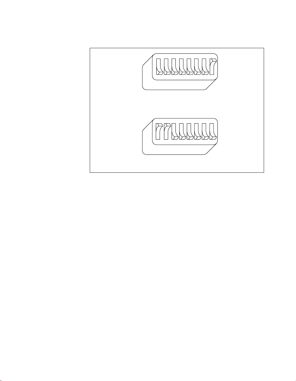
Chapter 4 VME-MXI-2 Configuration and Installation
Figure 4-2 shows switch settings for A16 base address hex C040 and F000.
a. Switch Set to A16 Base Address Hex C040 (Default)
1 2345678
OFF
U20
1 2345678
OFF
U20
b. Switch Set to A16 Base Address Hex F000
Figure 4-2. Base Address Selection
VME-MXI-2 Intermodule Signaling
If you will be installing more than one VME-MXI-2 in a single VMEbus
chassis, you must select a user-defined pin for use by the VME-MXI-2. The
VME-MXI-2 modules use this signal to disable the bus timeout unit(s) on
the other VME-MXI-2 modules during VMEbus accesses that map to the
MXIbus. This is done because the MXIbus bus timeout unit should be the
sole timer of any MXIbus access. Since bus timeout units on other VMEbus
modules cannot monitor this signal, they should be permanently disabl ed.
If it is not possible to disable a module’s bus timeout unit, it should be
configured to the highest setting to give MXIbus accesses as much time
as possible.
You can choose from three user-defined pins on J2/P2. The pin you select
must be bused on the VMEbus backplane between all slots that will have a
VME-MXI-2 installed. Use jumper W2 to select pin A5, C5, or C30 of
J2/P2, as shown in Figure 4-3.
Notice that a fourth position is also available on the jumper. This is the
factory-default setting, which does not connect the VME-MXI-2 to any
user-defined pin. You would use this option only if you are installing a
single VME-MXI-2 in a chassis.
VXI/VME-PCI8026 for Linux 4-4 www.ni.com
Page 57
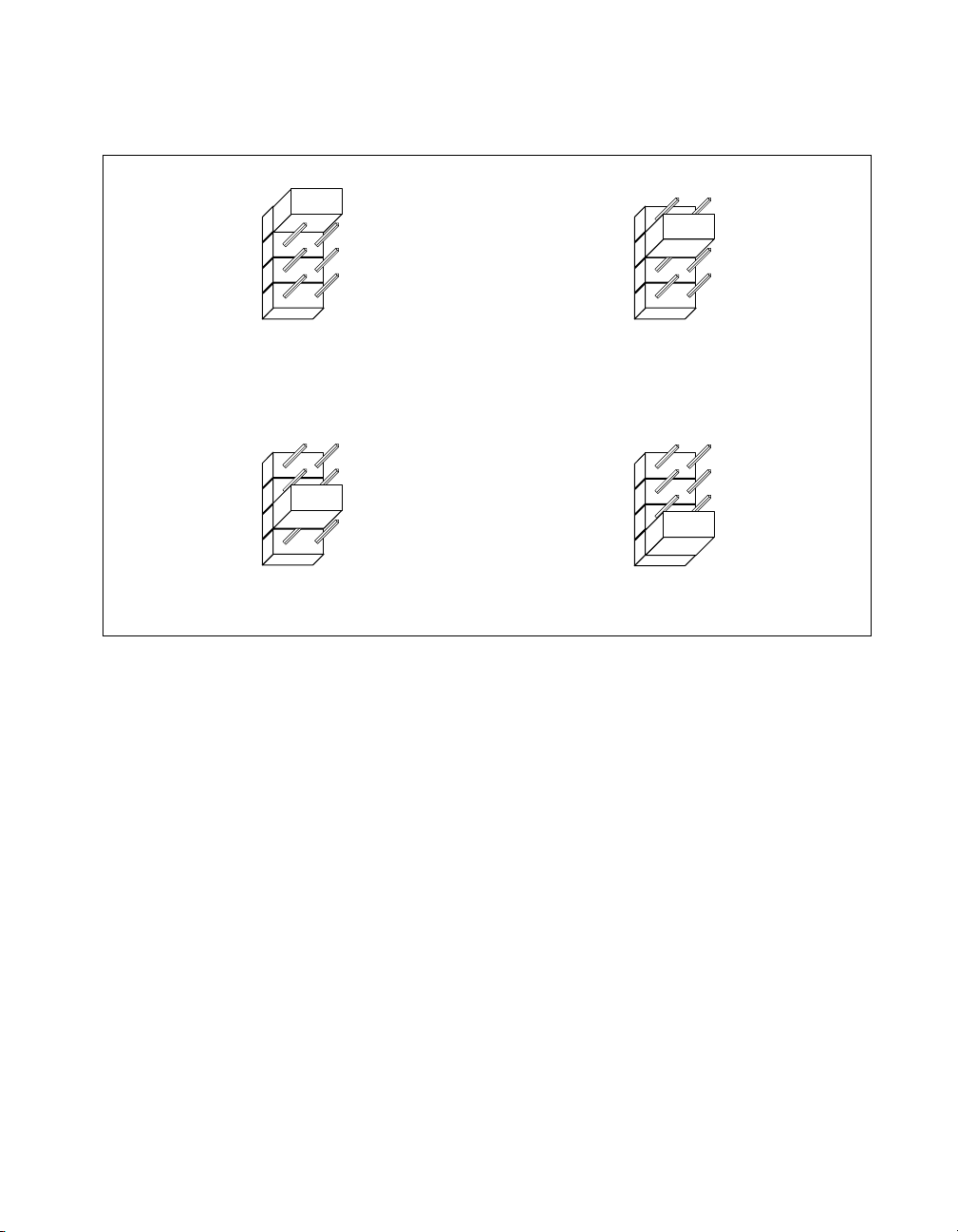
Chapter 4 VME-MXI-2 Configuration and Installation
Figure 4-3 shows the four intermodule signaling settings.
W2
A5
C5
C30
NC
a. User-Defined Pin A5 Selected
c. User-Defined Pin C30 Selected
W2
A5
C5
C30
NC
MXIbus Termination
W2
A5
C5
C30
NC
b. User-Defined Pin C5 Selected
W2
A5
C5
C30
NC
d. No User-Defined Pin Selected (Default)
Figure 4-3.
VME-MXI-2 Intermodule Signaling Settings
The first and last MXIbus devices connected to the MXIbus—whether it is
a single MXI-2 cable or daisy-chained MXI-2 cables—must terminate the
MXIbus. Any MXIbus devices in the middle of a MXIbus daisy chain must
not terminate the MXIbus.
The VME-MXI-2 automatically senses if it is at either end of the MXIbus
cable to terminate the MXIbus. You can manually control MXIbus
termination by defeating the automatic circuitry. Use switches 3 and 4 of
the four-position switch at location U21 to control whether MXIbus
termination is automatic (Figure 4-4a) , on ( Figure 4-4b), or off
(Figure 4-4c). The settings of switches 1 and 2 have no effect on MXIbus
termination.
Use switch 3 to select whether you want the VME-MXI-2 to automatically
control termination of the MXIbus. Switch 4 lets you manually control
whether to terminate the MXIbus when automatic termination is turned of f.
© National Instruments Corporation 4-5 VXI/VME-PCI8026 for Linux
Page 58
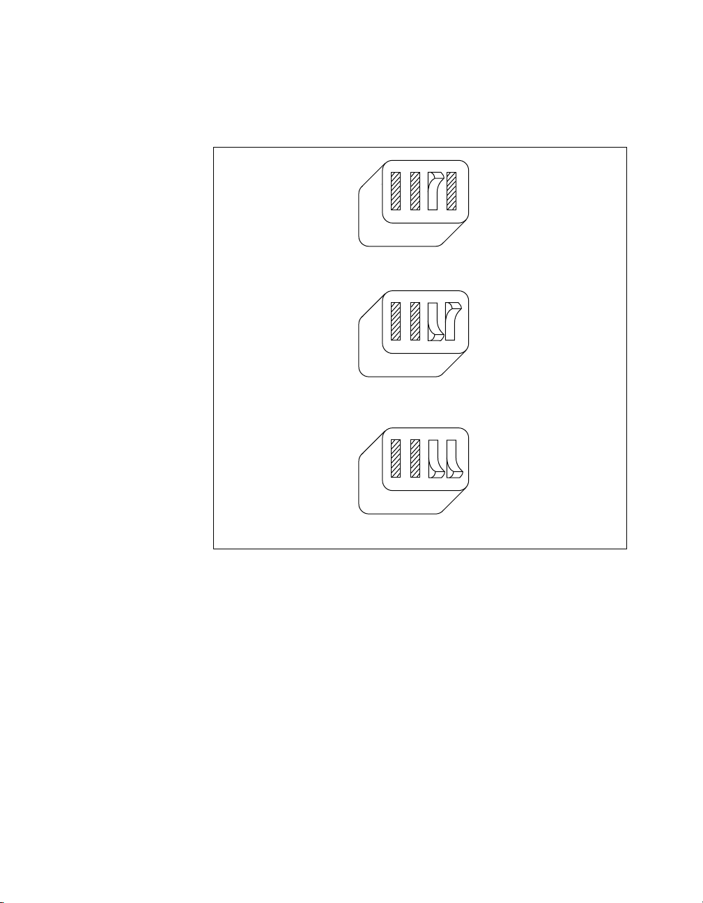
Chapter 4 VME-MXI-2 Configuration and Installation
Switch 4 has no effect when switch 3 is set for automatic MXIbus
termination; you must turn off automatic termination if you want to
manually control termination.
1234
U21
OFF
a. Automatic MXIbus Termination (Default)
1234
U21
OFF
b. Terminate MXIbus (On)
1234
U21
OFF
c. Do Not Terminate MXIbus (Off)
Figure 4-4. MXIbus Termination
VXI/VME-PCI8026 for Linux 4-6 www.ni.com
Page 59

Configuration EEPROM
The VME-MXI-2 has an onboard EEPROM, which stores default register
values that are loaded at power-on. The EEPROM is divided into two
halves—a factory-configuration half, and a user-configuration half. Both
halves were factory configured with the same configuration values so you
can modify the user-configurable half, while the factory-configured half
stores a back-up of the default user settings.
Use switches 1 and 2 of the four-position switch at location U21 to control
the operation of the EEPROM. The Restore Factory Configuration switch
(switch 1) causes the VME-MXI-2 to boot off the factory-configured half
instead of the user-modified settings. This is useful in the event that the
user-configured half of the EEPR OM becomes corrupted in such a way that
the VME-MXI-2 boots to an unusable state.
The Change Factory Configuration switch (switch 2 of U21) lets you
change the factory-default configuration settings by permitting writes to the
factory settings section of the EEPROM. This switch serves as a safety
measure and should not be needed under normal circumstances. When this
switch is off (its default setting) the factory configuration of the EEPROM
is protected so any writes to the factory area will be ignored. The factory
area is protected regardless of the setting of switch 1 of U21.
Chapter 4 VME-MXI-2 Configuration and Installation
Figure 4-5 shows the configuration settings for EEPROM operation. The
settings of switches 3 and 4 have no effect on EEPROM configuration.
© National Instruments Corporation 4-7 VXI/VME-PCI8026 for Linux
Page 60
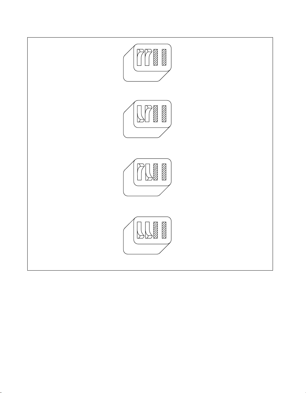
Chapter 4 VME-MXI-2 Configuration and Installation
a. Boot from User Configuration (Factory Configuration Protected) (Default)
b. Boot from Factory Configuration (Factory Configuration Protected)
1234
U21
OFF
1234
U21
OFF
1234
U21
OFF
c. Boot from User Configuration (Factory Configuration Unprotected)
1234
U21
OFF
d. Boot from Factory Configuration (Factory Configuration Unprotected)
Figure 4-5. EEPROM Operation
Onboard DRAM
The VME-MXI-2 can accommodate up to two 1.35 in. DRAM SIMMs.
Table 4-1 lists the SIMMs you can use. You can use 32-bit or 36-bit
SIMMs since DRAM parity is not required. Because the VME-MXI-2
supports only one organization at a time, all SIMMs installed must be of the
same type. Use Bank 0 first when installing SIMMs. This allows you to
install up to 64 MB. The VME-MXI-2 supports DRAM speeds of 80 ns
or faster.
VXI/VME-PCI8026 for Linux 4-8 www.ni.com
Page 61
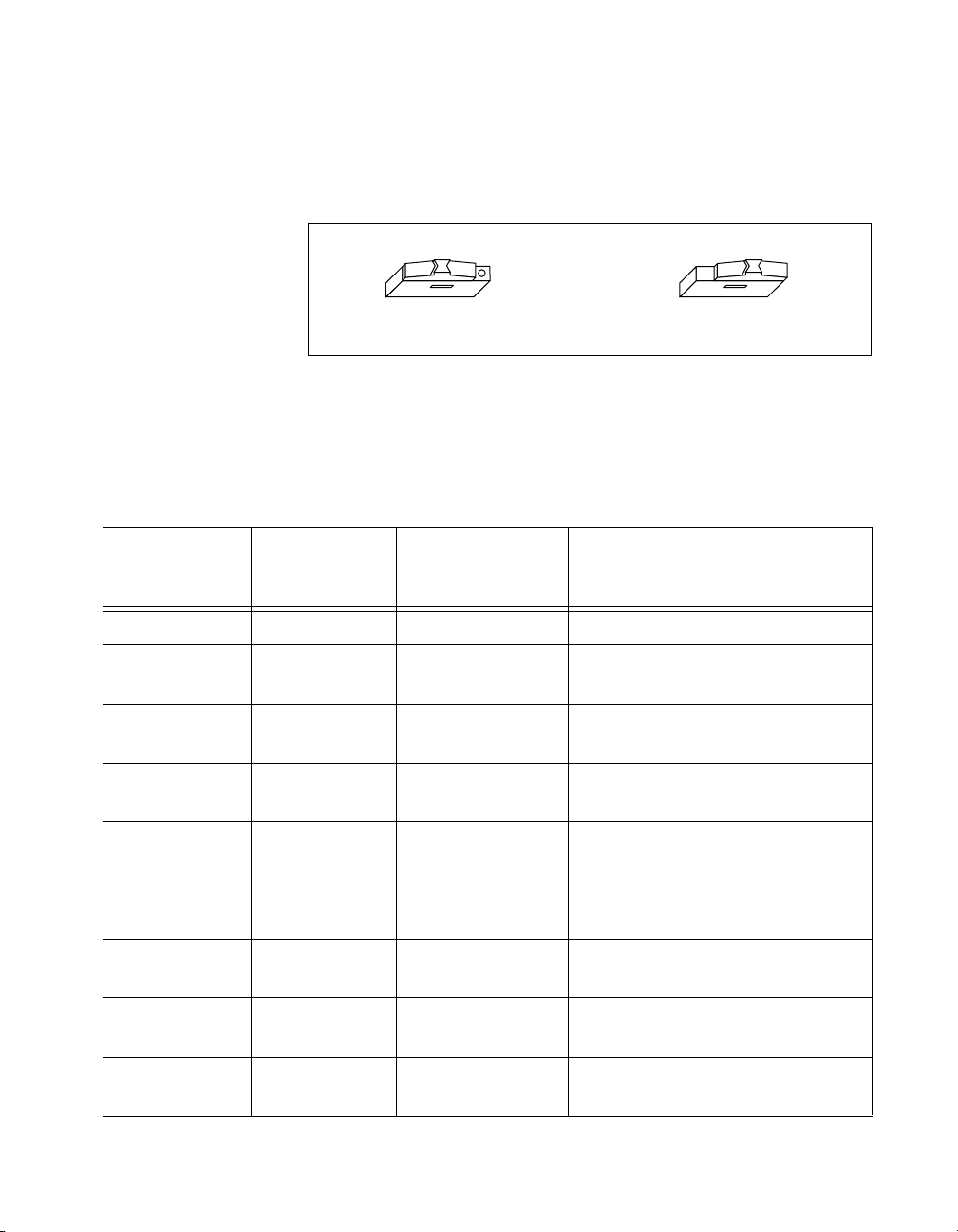
Chapter 4 VME-MXI-2 Configuration and Installation
Switch S2 is used to select the size of each SIMM. If the SIMMs are
4M× 32 or larger, S2 should be in the OFF setting as shown in
Figure 4-6a. For SIMMs smaller than 4 M × 32, use the ON setting as
shown in Figure 4-6b.
S2
a. 4 M x 32 and Larger
Figure 4-6.
SIMM Size Configuration
b. Smaller than 4 M x 32
Refer to Table 4-1 for how to adjust the switch (ON or OFF) for all
supported DRAM configurations. Many of the DRAM options are
available from National Instruments.
Table 4-1.
VME-MXI-2 DRAM Configurations
National
Instruments
Bank 0 Bank 1 Total DRAM
Option?
— — 0 — —
256 K × 32 or
— 1 MB — ON
256 K × 36
256 K × 32 or
256 K × 36
512 K × 32 or
256 K × 32 or
2 MB — ON
256 K × 36
— 2 MB — ON
512 K × 36
S2
Switch Setting
of S6
512 K × 32 or
512 K × 36
1 M × 32 or
512 K × 32 or
4 MB — ON
512 K × 36
— 4 MB YES ON
1M× 36
1 M × 32 or
1M× 36
2 M × 32 or
1 M × 32 or
8 MB — ON
1M× 36
— 8 MB YES ON
2M× 36
2 M × 32 or
2M× 36
© National Instruments Corporation 4-9 VXI/VME-PCI8026 for Linux
2 M × 32 or
2M× 36
16 MB — ON
Page 62
Chapter 4 VME-MXI-2 Configuration and Installation
Table 4-1.
Bank 0 Bank 1 Total DRAM
4 M × 32 or
4M× 36
4 M × 32 or
4M× 36
8 M × 32 or
8M× 36
8 M × 32 or
8M× 36
4 M × 32 or
4M× 36
8 M × 32 or
8M× 36
VME-MXI-2 DRAM Configurations (Continued)
— 16 MB YES OFF
— 32 MB YES OFF
Install the VME-MXI-2
This section contains general installation instructions for the VME-MXI-2.
Consult your VMEbus mainframe user manual or technical reference
manual for specific instructions and warnings.
1. Plug in your mainframe before installing the VME-MXI-2. The power
cord grounds the mainframe and protects it from electrical damage
while you are installing the module.
National
Instruments
Option?
32 MB — OFF
64 MB YES OFF
Switch Setting
of S6
Warning
mainframe should remain off until you are finished installing the VME-MXI-2 module.
VXI/VME-PCI8026 for Linux 4-10 www.ni.com
To protect both yourself and the mainframe from electrical hazards, the
2. Remove or open any doors or covers blocking access to the
mainframe slots.
3. Insert the VME-MXI-2 in the slot you have selected by aligning the top
and bottom of the board with the card-edge guides inside the
mainframe. Slowly push the VME-MXI-2 straight into the slot until its
plug connectors are resting on the backplane receptacle connectors.
Using slow, evenly distributed pressure, press the VME-MXI-2
straight in until it seats in the expansion slot. The front panel of the
VME-MXI-2 should be even with the front panel of the mainframe.
4. Tighten the retaining screws on the top and bottom edges of the
front panel.
5. Check the installation.
Page 63

6. Connect the cables as described in the following section before
restoring power.
7. Replace or close any doors or covers to the mainframe.
Connect the MXIbus Cable
There are two basic types of MXI-2 cables. MXI-2 cables can have either
a single connector on each end or a single connector on one end and a
double connector on the other end.
Connect the labeled end of the cable to the MXI-2 device that will be the
MXIbus System Controller . Connect the other end of the cable to the other
device. Be sure to tighten the screw locks to ensure proper pin connection.
Figure 4-7 shows the correct cabling for a VME system containing a
PCI-MXI-2 board in a PCI-based computer cabled to a VME-MXI-2
module residing in Slot 1 of a VMEbus mainframe. Notice that you can
expand your system to include other devices by using an additional MXI-2
cable. However, in such a case the first cable needs to have a double
connector on one end. You can then use a cable with a single connector on
each end to connect the last device on the MXIbus.
Chapter 4 VME-MXI-2 Configuration and Installation
© National Instruments Corporation 4-11 VXI/VME-PCI8026 for Linux
Page 64
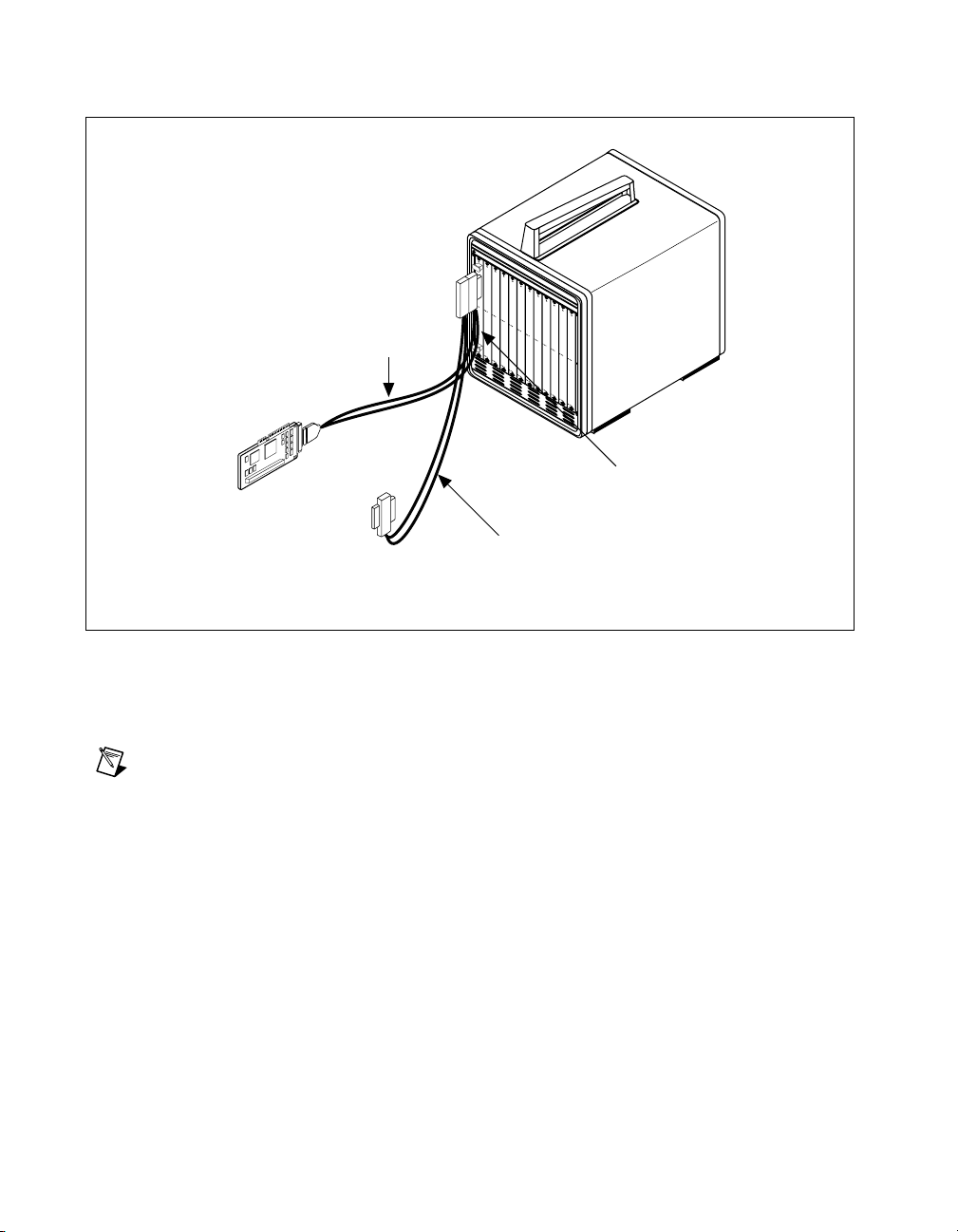
Chapter 4 VME-MXI-2 Configuration and Installation
MXI-2 Cable
PCI-MXI-2
Interface Module
To External
Computer
To Other
Mainframes
VME Chassis
VME-MXI-2 Module
Additional MXI-2 Cable
(Ordered Separately)
Figure 4-7. MXI-2 Cable Configuration Using a PCI-MXI-2 and a VME-MXI-2
When you have properly connected the MXI-2 cable, power on the
VMEbus mainframe and then the computer.
Note
Always turn on the mainframe first. Doing so makes it possible for your external
computer to access the VME boards in the mainframe upon startup.
VXI/VME-PCI8026 for Linux 4-12 www.ni.com
Page 65

NI-VXI/VISA Software
Installation
This chapter describes how to install and uninstall the NI-VXI/VISA
software for Linux.
Installing the NI-VXI/VISA Software for Linux
Before you begin, you may need to install Linux on your computer. Refer
to the Linux documentation for instructions. After your computer is booted
into Linux, you are ready to install the NI-VXI/VISA software.
To install NI-VXI/VISA for the PCI-MXI-2 for Linu x, perform the
following steps:
1. Insert the NI-VXI/VISA for Linux CD.
2. Login to your system as
3. Mount the CD-ROM.
4. To change the current directory to the mounted CD-ROM, type the
following command:
cd /mnt/cdrom
5. To run the installation script, type the following command:
./INSTALL
root
.
5
The
INSTALL
script uses
the files directly on other systems. The script also optionally installs
support for NI-VXI in LabVIEW.
You also can install the RPM files without going through the
script by using
systems. For example, to install NI-VXI in
type the following command:
rpm --prefix=/opt/nivxi -Uvh nivxi-pcimxi-1.6-1.i386.rpm
where
number will be different if you are installing a newer version.
© National Instruments Corporation 5-1 VXI/VME-PCI8026 for Linux
places NI-VXI and NI-VISA in their default locations. The
to install the packages on systems that support it or extracts
rpm
rpm, glint
is the version you are installing. Note that this version
1.6-1
, or
gnorpm
on RedHat or other RPM-based
on a RedHat 5.x system,
/opt
INSTALL
Page 66

Chapter 5 NI-VXI/VISA Software Installation
Note
If you use
rather than the
rpm
INSTALL
script, you must repeat this step for each
package you want to install.
If you install the software to a location other than the default, set the
appropriate environment variable:
VXIPNPPATH
for NI-VISA. See your manual for details.
NIVXIPATH
Please see the README file on the CD-ROM for additional important
information and instructions.
Removing the NI-VXI Driver for Linux
To uninstall the driver, you must meet the following requirements:
• You m ust have superuser privilege.
• The driver must not be in use.
for NI-VXI or
Typing
rpm -e nivxi-pcimxi nivisa
software.
Using the NI-VXI/VISA Software
The NI-VXI software is configured to be loaded in the
/usr/local/nivxi
another directory, set the
directory. For example, if you have installed NI-VXI in
type the following command:
setenv NIVXIPATH /usr2/nivxi
The NI-VISA software is configured to be loaded in the
/usr/local/vxipnp
another directory, set the
directory. For example, if you have installed NI-VXI in
the following command:
setenv VXIPNPPATH /usr2/vpp
Place these lines in your
(Bourne or Korn shells) so they will execute automatically the next time
you log in.
directory. If you have installed the software in
NIVXIPATH
directory. If you have installed the software in
VXIPNPPATH
.cshrc
removes the NI-VXI/VISA
environment variable to your
/usr2/nivxi
environment variable to your
/usr2/vpp
or
.login
(C shell) or
.profile
,
, type
VXI/VME-PCI8026 for Linux 5-2 www.ni.com
Page 67

Chapter 5 NI-VXI/VISA Software Installation
Completing the Software Installation
After the software is installed, run
resman
Instruments Resource Manager. You must run
, which is the National
resman
every time the
chassis power is cycled so that your application can access devices in the
VXI/VME chassis.
After you run
program
vxitedit
resman
, you are ready to use the NI-VXI Resource Editor
to interactively configure the hardware in your system.
Continue with Chapter 6, NI-VXI Configuration Utility, for instructions on
using the configuration editors in
vxitedit
.
© National Instruments Corporation 5-3 VXI/VME-PCI8026 for Linux
Page 68

NI-VXI Configuration Utility
This chapter contains instructions for using the VXI Text Resource Editor
utility of the NI-VXI software to configure the PCI-MXI-2 and the
VXI-MXI-2 or VME-MXI-2.
6
vxitedit
system and to edit the manufacturer name and ID numbers, the model
names of VXI and non-VXI devices in the system, and the system interrupt
configuration information. This program also displays the system
configuration information generated by the Resource Manager.
is the VXI resource editor program that you use to configure the
Running the VXItedit Configuration Utility
To run
vxitedit
vxitedit
NIVXIPATH
NI-VXI software added to them.
find the different configuration files (
files (
*.hlp
program if
Most of the features on the PCI-MXI-2, VXI-MXI-2, and VME-MXI-2 are
configurable through software, using
hardware switches or jumpers on the boards themselves. In addition, the
vxitedit
The rest of this chapter describes only the features of the PCI-MXI-2
Configuration Editor and the VXI/VME-MXI-2 Configuration Editor.
For instructions on using the other editors, refer to the online help.
, type
vxitedit
from any directory, but make sure that both the
environment variables have the destination directory of the
) during its execution. The default pathname used by the
NIVXIPATH
utility can override some of the hardware settings.
is not set is
at the command prompt. You can run
NIVXIPATH
*.cfg
/usr/local/nivxi
vxitedit
is used by the application to
), table files (
and
PATH
), and help
*.tbl
.
, rather than through
© National Instruments Corporation 6-1 VXI/VME-PCI8026 for Linux
Page 69

Chapter 6 NI-VXI Configuration Utility
PCI-MXI-2 Configuration Editor
When you run the PCI-MXI-2 Configuration Editor, the screen displays
the serial number and hardware revision of the PCI-MXI-2 board in
addition to several configuration options.
The first three options are
• Logical Address Configuration Editor
• Device Configuration Editor
• Bus Configuration Editor
When making changes to the PCI-MXI-2 through these editors, remember
that the changes do not take effect until you commit them by selecting the
Update Current Configuration option.
Before proceeding to a description of each field in these editors, revie w the
remaining four options of the PCI-MXI-2 Co nfiguration Edi tor. These
options directly relate to how you can use the changes you make using the
configuration editors, which are described after the options.
Update Current Configuration
Use this option to write the configuration settings to the PCI-MXI-2
EEPROM and files used by NI-VXI. It configures the PCI-MXI-2 to be
consistent with the configuration EEPROM. Notice that some of the
configuration settings cannot take effect until you reset the machine, either
by using the reset button or by turning the power off and on again.
Record Configuration to File
With this option you can save your configuration settings to a file. Notice
that this option does not write the configuration settings to the PCI-MXI-2
configuration EEPROM.
If you want to update the PCI-MXI-2 configuration settings, use the
Update Current Configuration option instead.
Load Configuration from File
You can use this option to load your configuration settings from a file. This
action only updates the configuration settings in your editor. This does not
write the configuration settings to the PCI-MXI-2 configuration EEPROM.
To update the configuration use the Update Current Configuration
option for the changes to take effect.
VXI/VME-PCI8026 for Linux 6-2 www.ni.com
Page 70
Revert to Current Configuration
If you made changes to the configuration settings without committing those
changes (writing to configuration EEPROM), you can revert the
configuration settings to the values they had before you made the changes.
Note
You can successfully revert only if you have
Configuration option.
Logical Address Configuration Editor
The options in the Logical Address Configuration Editor fall into three
categories—Device Settings, VXI Shared Memory, and Resource
Manager. The following paragraphs describe the options you can select for
each of the fields.
Device Settings
The Device Settings category contains the options to set the logical
address, device type, and address space of the PCI-MXI-2.
Logical Address
This parameter sets the MXI logical address of the PCI-MXI-2. The
following table shows the allowable range of values and the default value.
Chapter 6 NI-VXI Configuration Utility
yet selected the Update Current
NOT
Logical Address Range Default Value
0 to 254 0
Device Type
This field indicates the classification of the PCI-MXI-2. The default value
is MBD, designating a message-based device. The following table shows
the available options.
Classification Setting
Extended Device
Message-Based Device
Register-Based Device
© National Instruments Corporation 6-3 VXI/VME-PCI8026 for Linux
EXT
MBD
RBD
Page 71

Chapter 6 NI-VXI Configuration Utility
The device type affects only the contents of the Device Class field in the
Device Type register. The functionality of the other registers does not
change.
Address Space
This field indicates the addressing mode(s) of the device’s operational
registers. The PCI-MXI-2 can be configured in one of three ways. The
default addressing mode is for A16 space only. Your other options are
A16/A24 and A16/A32.
Notice that the options in the VXI/VME Shared Memory group are
disabled when the addressing mode is A16. Only if you select A16/A24
or A16/A32 are the following options relevant:
• VXI/VME Shared RAM Size
• Shared RAM Pool
• Advanced
– Byte Swapping
– Memory Select
– Mapping
VXI/VME Shared Memory
Linux does not support sharing of system RAM. You can, however, share
RAM that is installed on the VXI-MXI-2 or VME-MXI-2.
Resource Manager
The only option under the Resource Manager portion of the Logical
Address Configuration Editor is the Resource Manager Delay option.
Resource Manager Delay
Note
This field is effecti ve only when the PCI-MXI-2 is at its default logical address of 0.
The PCI-MXI-2 is the Resource Manager only if its logical address is 0.
This field specifies the time in seconds that the Resource Manager (RM)
waits before accessing any other VXI/VMEbus device’s A16 configuration
registers.
RM Delay Range Default Value
0 to 65535 s 5
VXI/VME-PCI8026 for Linux 6-4 www.ni.com
Page 72
Device Configuration Editor
The following paragraphs describe the options you can select for each of
the fields in the Device Configuration Editor.
Default Controller (LA –1)
Many NI-VXI functions use controller as a parameter with –1 accepted as
a valid value. You use this selection to determine which controller you are
referring to when you use –1 in these NI-VXI functions. Review the
descriptions of the NI-VXI functions to determine which are applicable for
this option.
By default, the Default Controller (LA –1) option is set to First remote
controller, so that any NI-VXI functions that are passed the v alue of –1 for
the controller parameter will be executed on the first VXI/VME-MXI-2 in
the MXI-2 chain. If you select the Local controller option, the NI-VXI
functions execute on the PCI-MXI-2.
System IRQ Level
The remote controllers—in this case the VXI/VME-MXI-2—can report
events such as triggers and DMA to the PCI-MXI-2 through a VXI IRQ
line. This field selects which VXI IRQ level the remote controllers should
use to report events to the PCI-MXI-2.
Chapter 6 NI-VXI Configuration Utility
Interrupt Request Levels Default Value
1 to 7 1
Servant Area Size
This field designates the servant area size, which is supplied to the
Resource Manager in response to the Read Servant Area command (if the
PCI-MXI-2 is not the Resource Manager in your system). The servant area
size is an 8-bit value (0 through 255) that indicates the servant area. The
servant area begins at the logical address following the PCI-MXI-2 logical
address, and includes N contiguous logical addresses, where N is the value
of the servant area size. This field is meaningful only when the PCI-MXI-2
is configured as a message-based device.
Servant Area Range Default Value
0 to 255 0
© National Instruments Corporation 6-5 VXI/VME-PCI8026 for Linux
Page 73
Chapter 6 NI-VXI Configuration Utility
Note
If the PCI-MXI-2 is the Resource Manager (Logical Address 0), this setting is
irrelevant.
Number of Handlers
This field gives the number of interrupt handlers that the PCI-MXI-2
supports.
Number of Interrupters
This field gives the number of interrupters that the PCI-MXI-2 supports.
Note
If the PCI-MXI-2 is the Resource Manager (Logical Address 0), this setting is
irrelevant.
Interrupt Handlers Default Value
0 to 7 1
Interrupters Default Value
0 to 7 0
Protocol Register
This field specifies the contents of the Protocol register, indicating which
protocols the device supports. This field is meaningful only when the
PCI-MXI-2 is configured as a message-based device. The default value is
FF0 (Commander, Signal Register, Master).
Read Protocol Response
This field specifies the response value to a Read Protocol command
received by the PCI-MXI-2 from the Resource Manager (if the PCI-MXI-2
is not the Resource Manager in your system). This field is meaningful only
when the PCI-MXI-2 is configured as a message-based device. The default
value is 0x8448 (Response Generation, Event Generation, Programmable
Handler, Word Serial Trigger, Instrument, Extended Longword Serial,
Longword Serial).
Note
If the PCI-MXI-2 is the Resource Manager (Logical Address 0), this setting is
irrelevant.
VXI/VME-PCI8026 for Linux 6-6 www.ni.com
Page 74

Bus Configuration Editor
This section describes the options you can select for each of the fields in the
Bus Configuration Editor.
MXI Bus
The following paragraphs describe the options for the MXI Bus portion of
this editor.
MXI System Controller
You can use the MXI System Controller option to determine whether the
PCI-MXI-2 acts as the MXIbus System Controller. The three options are
Auto, Yes, and No.
When the Auto setting is active (the default setting), the PCI-MXI-2
automatically can sense from the MXIbus cable whether it should be
the controller. This setting requires that the cable is attached properly
before making any NI-VXI function calls or attempting to use the
VXI/VME-MXI-2 Configuration Editor. Refer to Connect the MXIbus
Cable at the end of either Chapter 3, VXI-MXI-2 Configu ration
and Installation, or Chapter 4, VME-MXI-2 Configuration
and Installation, of this manual.
Chapter 6 NI-VXI Configuration Utility
You can select the Yes or No options to manually determine whether the
PCI-MXI-2 should be the MXIbus System Controller. You must still be
certain to cable the MXIbus system appropriately when you make either of
these selections.
Note
Make sure the MXI-2 cable is connected to the PCI-MXI-2 when you power on or
reboot the computer. This is required for the PCI-MXI-2 to automatically detect whether it
will be the MXIbus System Controller.
MXI Bus Timeout
The MXIbus Bus Timeout (BTO) is a watchdog timer for transfers on the
MXIbus. The MXIbus BTO operates only when the PCI-MXI-2 is acting
as the MXIbus System Controller.
After the specified amount of time has elapsed, the BTO circuitry
terminates a MXIbus cycle if no slave has responded. The BTO is also
disabled when the current MXIbus cycle maps to the VXI/VMEbus through
a VXI/VME-MXI-2.
© National Instruments Corporation 6-7 VXI/VME-PCI8026 for Linux
Page 75

Chapter 6 NI-VXI Configuration Utility
The default timeout v alue is 1 ms. If the Enable MXI-2 Auto Retry option
is enabled, you should use a MXI Bus Timeout of 1 ms or greater.
MXI CLK10
The PCI-MXI-2 is capable of either receiving or driving the MXIbus
CLK10 signal.
You can use the Drive or Receive options of the MXI CLK10 feature to
control the direction of the MXIbus CLK10 signal. By default all MXI-2
boards receive MXI CLK10 (the Receive option is active); therefore, you
must choose one board on your MXI-2 bus to drive CLK10 by changing the
value of the option to Drive. For most configurations, it is recommended to
choose the System Controller as the CLK10 source for simplicity. The only
exception you may want to make is if you want your triggers synchronous
to the VXI 10 MHz clock.
Caution
a second device driving MXIbus CLK10 could damage the device.
Do not configure more than one MXIbus device to drive MXIb us CLK10. Having
MXI Transfer Limit
Use this feature to control how many data transfers the PCI-MXI-2 will
perform on the MXIbus before releasing it to another master device that is
requesting use of the bus. The default setting holds the MXIbus for an
unlimited period of time.
The other options you can choose from are 256, 64, and 16 transfers. If you
do not want the PCI-MXI-2 to hold the MXIbus for an unlimited period of
time, you can use this option to select one of these values.
MXI-2 Auto Retry
The PCI-MXI-2 has an automatic retry feature for cycles that map from the
MXI bus to the PCI bus. By default this option is enabled.
Normally, when a cycle maps from the MXI bus to the PCI bus, any retry
response received on the PCI bus is passed to the MXI bus. When the
MXI-2 auto retry feature is enabled, the PCI-MXI-2 automatically retries
any PCI cycle when the PCI host responds to a cycle with a retry. The
PCI-MXI-2 automatically continues to retry the PCI cycle until it receives
either a DTACK or BERR response, which it then passes to the MXI bus.
This is the default situation because many external masters do not support
VXI/MXI retries. If the external master does support retries, it may be
beneficial to disable the MXI-2 auto retry feature. With this feature
VXI/VME-PCI8026 for Linux 6-8 www.ni.com
Page 76

Chapter 6 NI-VXI Configuration Utility
disabled, you can lower the MXI Bus Timeout because there will be no
delay due to the inward cycles being retried.
Note
The PCI-MXI-2 has a limit on the number of automatic retries it will perform on any
one cycle. If the limit is exceeded and the PCI-MXI-2 receiv es anothe r retry, it will pass a
retry back to the MXIbus even though the Enable MXI-2 Auto Retry option is selected.
A24/A32 Write Posting
This field determines whether to enable write posting for incoming slave
accesses to A24/A32 VXI/VME shared RAM. By default this option is
disabled.
Enabling write posting will increase the throughput of your inward cycles.
However , you should not enable write posting unless the destination of your
inward A24/A32 cycles is onboard RAM, because cycles to onboard RAM
will always complete successfully.
PCI Bus
The following paragraphs describe the options for the PCI Bus portion of
this editor.
User Window and Driver Window
The PCI-MXI-2 driver requires the use of two PCI windows: a user
window and a driver window. Calling the
MapVXIAddress()
allocates regions of the user window to your application.
VXIpoke()
accesses are performed through this window. NI-VXI uses the
driver window to perform high-level functions such as
VXIout()
, and to access registers on the PCI-MXI-2 and
VXI/VME-MXI-2.
The windows are mapped to PCI base address registers and determine the
amount of PCI memory space the PCI-MXI-2 requests from the PCI system
during initialization.
User Window Size
The amount of space you can allocate for the user window is system
dependent. You can use the Size option to select the size of the user window
(minimum of 4 KB, maximum of 2 GB). The more you increase the size of
the user window, the larger the window you can map in
MapVXIAddress()
© National Instruments Corporation 6-9 VXI/VME-PCI8026 for Linux
.
function
VXIpeek()
VXIin()
and
and
Page 77

Chapter 6 NI-VXI Configuration Utility
You can also disable this option. Disabling the user window causes the
PCI-MXI-2 to request the minimum amount of address space on the
PCI bus. With the window disabled, you will be unable to perform any
low-level function calls such as
MapVXIAddress()
It is recommended to have a user windo w of at least 64 KB, and the default
setting for the user window is set at this value. If you are going to be
initiating transfers to a wide variety of addresses in both A24 and A32, you
should increase the size of the user window. Any change you make to the
size of the user window requires that you reboot your computer.
The size of the driver window, however, is system defined and is not user
configurable.
Note
Neither the user window nor the driv er windo w can be placed belo w 1 MB with the
Linux NI-VXI driver. Therefore, the Place below 1 MB option and the Window Base
option will always be disabled.
Expansion ROM
Use the Enable expansion ROM option to enable or disable the
PCI expansion ROM. The expansion ROM is enabled by default. It is
recommended to retain the default setting. This option is included in
vxitedit
PCI expansion ROM.
VXIpeek(), VXIpoke()
, and
.
in case future versions of the PCI-MXI-2 do not implement a
VXI/VME-MXI-2 Configuration Editor
Before running the VXI/VME-MXI-2 Configuration Editor, you must
run
resman
Note
Through out this section, the term VXI/VME-M XI -2 denotes that the information
applies equally to the VXI-MXI-2 or the VME-MXI-2.
Upon entering the VXI/VME-MXI-2 Configuration Editor , the program
displays a list of VXI/VME-MXI-2 boards that
system.
Select the device you want to configure from the Detected Boards
pull-down list, or you can select User LA and type in the board’s logical
address in the Logical Address field. Select OK to enter the editor or
Cancel to return to the main menu.
VXI/VME-PCI8026 for Linux 6-10 www.ni.com
.
resman
detected in your
Page 78

After finding a VXI/VME-MXI-2, the VXI/VME-MXI-2 Configuration
Editor displays a menu you can use to modify its configuration settings.
The menu displays the current settings of the module. Notice that it also
shows the hardware revision and serial number of the VXI/VME-MXI-2.
LA Selection and Logical Address
You can set or modify the logical address of the VXI/VME-MXI-2 either
within the VXI/VME-MXI-2 Configuration Editor itself or with the
onboard 8-position DIP switch. To select the configuration method you
prefer, use the LA Selection options.
The default selection is the Switch option. Notice that the Logical Address
option is inaccessible, since it would have no effect. In this option you need
to change the hardware switch setting on the VXI/VME-MXI-2 itself if you
want to change the logical address.
If you select Software for this option, you can then use the Logical
Address option to select a logical address within the range of 1 to 254.
If you use this option, the hardware switch setting has no effect and you
must use the VXI/VME-MXI-2 Configuration Editor to change the
logical address.
Chapter 6 NI-VXI Configuration Utility
Address Space and Requested Memory
The VXI/VME-MXI-2 requires at least 16 KB of address space in A24
space or at least 64 KB in A32 space. Use the Address Space option
to select whether you want to use A24 space or A32 space. Use the
Requested Memory option to set the amount of memory space that the
VXI/VME-MXI-2 will request. You can select up to 8 MB in A24 space
and up to 2 GB in A32 space. The default setting uses the minimum
requirement of 16 KB in A24 space.
These options are necessary if you change the amount of DRAM installed
on the VXI/VME-MXI-2. The amount of memory you set with the
Requested Memory option should match the amount of DRAM installed
on the VXI/VME-MXI-2. If no DRAM is installed, keep the default setting
of 16 KB. Notice that the smallest valid amount in A32 space is 64 KB.
Caution
4 KB of memory space. This 4 KB space maps to the registers on the VXI/VME-MXI-2
and does not access onboard DRAM. Accessing this region will cause your
VXI/VME-MXI-2 to behave incorrectly.
© National Instruments Corporation 6-11 VXI/VME-PCI8026 for Linux
If you install DRAM into the VXI/VME-MXI-2, do not attempt to use the first
Page 79

Chapter 6 NI-VXI Configuration Utility
Note
If you do not want to lose 4 KB of DRAM you can get around this limitation by
setting the Requested Memory option to double the amount that is installed on the
VXI/VME-MXI-2, because the DRAM is aliased throughout the remainder of the
requested memory space. The DRAM should then be accessed in the upper half of the
requested memory space.
A16 and A24/A32 Write Posting
The VXI/VME-MXI-2 can increase performance with its capability to post
write cycles from both the MXIbus and the VXI/VMEbus. Write cycles
should be posted only to devices that cannot return a BERR signal, because
the BERR will not be reported to the originating master.
Select the appropriate option(s) if you want to use either A16 or A24/A32
write posting. By default, both options are disabled.
The A16 write posting option affects only write cycles that map through
the A16 window from the VXI/VMEbus to the MXIbus and vice versa.
A16 write cycles in VXI configuration space are never posted regardless
of the setting of this option.
The A24/A32 write posting option affects write cycles that map through the
A24 window and A32 window from the VXI/VMEbus to the MXIbus and
vice-versa. This option also affects write cycles to the VXI/VME-MXI-2
itself via its requested memory space from both the VXI/VMEbus and the
MXIbus. For more information on the A16, A24, and A32 windows, refer
to VXI-6, VXIbus Mainframe Extender Specification.
Interlocked Mode
Interlocked arbitration mode is an optional mode of operation in which
at any given moment the system can perform as if it were one large
VXI/VMEbus mainframe with only one master of the entire
system—VXI/VMEbus and MXIbus. This mode of operation prevents
deadlocks by interlocking all arbitration in the VXI/VMEbus/MXIbus
system. By default, this option is disabled, which puts the
VXI/VME-MXI-2 in normal operating mode.
In normal operating mode (non-interlocked), multiple masters can operate
simultaneously in the VXI/VMEbus/MXIbus system. A deadlock occurs
when a MXIbus master requests use of a VXI/VMEbus resource in another
VXI/VMEbus mainframe while a VXI/VMEbus master in that mainframe
is in the process of requesting a resource across the MXIbus. When this
situation occurs, the VXI/VMEbus master must give up its bus ownership
to resolve the conflict. The RETRY signal is used to terminate the transfer
VXI/VME-PCI8026 for Linux 6-12 www.ni.com
Page 80

Chapter 6 NI-VXI Configuration Utility
on the VMEbus; however , de vices in the VXI/VMEbus mainframe must be
able to detect a RETRY caused by a deadlock condition so that they can
retry the operation. Any master device that cannot detect the retry protocol
will interpret the response as a BERR signal instead.
The VXI/VME-MXI-2 is shipped from the factory configured for normal
operating mode (non-interlocked). If MXIbus transfers will be occurring
both into and out of the mainframe and the VXI/VMEbus modules in your
system do not have the capability for handling retry conditions, you may
want to configure the VXI/VME-MXI-2 for interlocked arbitration mode
by selecting the Enable option. In this mode, no software provisions for
deadlock conditions are required. However, parallel accesses in separate
VXI/VMEbus mainframes are no longer possible, and system performance
may be lower than in normal operating mode.
In a VXI/VMEbus/MXIbus system, you can configure some
VXI/VME-MXI-2 modules for normal operating mode and others for
interlocked arbitration mode. The VXI/VMEbus mainframes configured in
interlocked arbitration mode will be interlocked with each other and the
mainframes configured for normal operating mode can perform transfers in
parallel.
This type of system configuration is recommended if you have one of the
following situations:
• A VXI/VMEbus mainframe with only slave devices and no masters.
Without bus masters, there is no chance for deadlock. You can
configure the VXI/VME-MXI-2 devices in this mainframe for normal
operating mode.
• A VXI/VMEbus mainframe with both masters and slaves, but the
masters communicate only with the slaves in their mainframe. The
masters never attempt transfers across the MXIbus, so there is no
chance for deadlock when a MXIbus master attempts a transfer
into the VXI/VMEbus mainframe. You can configure the
VXI/VME-MXI-2 devices in this mainframe for normal
operating mode.
• A VXI/VMEbus mainframe in which all masters that perform cycles
across the MXIbus support the VME64 RETRY protocol. You can
configure the VXI/VME-MXI-2 devices in this mainframe for normal
operating mode because all masters that could cause a deadlock will
automatically retry the operation.
© National Instruments Corporation 6-13 VXI/VME-PCI8026 for Linux
Page 81

Chapter 6 NI-VXI Configuration Utility
VXI/VME Bus Options
Use the options in this group to control features of the VXI/VMEbus
interface on the VXI/VME-MXI-2.
VMEbus System Controller
You can use the System Controller option to override the jumper setting
on the VXI-MXI-2. The VME-MXI-2 does not have an onboard jumper
setting for this option. When the Auto setting (the default setting) is active,
the onboard jumper setting determines if the VXI-MXI-2 is the VXI Slot 0
device. For more information, refer to the VXIbus Slot 0/Non-Slot 0 section
in Chapter 3, VXI-MXI-2 Configuration and Installation.
Otherwise, choose either the Yes or No option. Notice that selecting either
of these options overrides the onboard jumper setting on the VXI-MXI-2,
so it will not matter how the jumper is set. You would need to run the
VXI/VME-MXI-2 Configuration Editor again if you decide to change
the VMEbus System Controller (VXI Slot 0) setting at a later time.
Caution
(VXI Slot 0) into another slot without first reconfiguring it to either Non-Slot 0
or automatic configuration. Neglecting to do this could damage the VXI/VME-MXI-2, the
VXI/VMEbus backplane, or both.
This means that you should use either the No option or the Auto option. For the
VXI-MXI-2, you also have the option of changing the hardware jumper setting.
Do not install a VXI/VME-MXI-2 configured for VMEbus System Controller
VXI/VME Bus Timeout Value
The VXI/VMEbus Bus Timeout (BTO) is a watchdog timer for transfers on
the VMEbus Data Transfer bus. After the specified amount of time has
elapsed, the BTO circuitry terminates a VMEbus cycle if no slave has
responded. The VXI/VME-MXI-2 must provide the VXI/VMEbus BTO
for proper operation because when a MXIbus cycle is involved, the
VXI/VMEbus timeout must be disabled and the MXIbus BTO enabled.
You should disable the BTO of any other BTO module residing in the
mainframe. If this is not possible, set its VXI Bus Timeout option to its
maximum setting to give the MXIbus cycles as much time as possible to
complete.
The lowest value in the allowable range is 15 µs and the highest value is
256 ms. The default value is 125 µs.
VXI/VME-PCI8026 for Linux 6-14 www.ni.com
Page 82

Chapter 6 NI-VXI Configuration Utility
VXI/VME Auto Retry
The VXI/VME-MXI-2 has an automatic retry feature for cycles that map
from the VXI/VMEbus to the MXIbus. By default this option is disabled.
Normally, when a cycle maps from the VXI/VMEbus to the MXIbus, any
retry response received on the MXIbus is passed to the VXI/VMEbus. If
you enable the Auto Retry feature, the VXI/VME-MXI-2 automatically
retries any MXI cycle that receives a retry response instead of passing a
retry response back to the VXI/VMEbus. The VXI/VME-MXI-2
automatically continues to retry the MXI cycle until it receives either a
DTACK or BERR response, which it then passes to the VXI/VMEbus.
Notice that the VXI/VME-MXI-2 has a limit on the number of automatic
retries it will perform on any one cycle. If the limit is exceeded and the
VXI/VME-MXI-2 receives another retry, it will pass a retry back to the
VXI/VMEbus even though Auto Retry is enabled.
Transfer Limit
You can use this feature to control how many data transfers the
VXI/VME-MXI-2 will perform on the VXI/VMEbus before releasing it to
another master device that is requesting use of the bus.
The available options you can choose from are 16, 64, and 256 transfers.
If you do not want the VXI/VME-MXI-2 to hold the VXI/VMEbus long
enough to perform 256 transfers (the default value), you can use this option
to select a smaller value.
Arbiter Type
You can use the Arbiter Type feature to configure the VXI/VME-MXI-2
as either a Priority or Round Robin VMEbus arbiter. This option is
applicable only if the VXI/VME-MXI-2 you are configuring is a VMEbus
System Controller (VXI Slot 0) device. The default value is Priority.
When configured for Priority arbitration, the VXI/VME-MXI-2 grants the
bus to the highest pending bus request level. In Round Robin arbitration
mode, the VXI/VME-MXI-2 grants the bus to the next highest bus request
level after the level of the previous bus owner. This effectively gives the
same priority to each bus request level. Refer to the VMEbus specification
for more information on the different types of arbiters.
© National Instruments Corporation 6-15 VXI/VME-PCI8026 for Linux
Page 83

Chapter 6 NI-VXI Configuration Utility
Request Level
The VXI/VME-MXI-2 uses one of the four VMEbus request levels
(0 to 3) to request use of the VME Data Transfer Bus (DTB). The
VXI/VME-MXI-2 requests use of the DTB whenever an external MXIbus
device, such as a PCI-based computer with a PCI-MXI-2 interface,
attempts a transfer that maps into the VXI/VMEbus mainframe.
The VXI/VME-MXI-2 uses VMEbus request level 3 by default, as required
by the VXIbus specification. This is suitable for most VXIbus systems.
However, you can change the VXI/V ME-MXI-2 to use any of the other
three request levels (0, 1, or 2) by changing the setting of the Request
Level option. Y ou may want to change request le vels to change the priority
of the VXI/VME-MXI-2 request signal. For more information, refer to the
VMEbus specification.
VXI/VME Fair Requester
The VXI/VME-MXI-2 is always a Release On Request requester.
However, you can configure whether the VXI/VME-MXI-2 acts as either
a fair or unfair requester on the VXI/VMEbus. By default this option is
enabled, signifying a fair requester. For more information on the different
types of requesters, refer to the VMEbus specification.
Arbiter Timeout
An arbitration timeout feature is available on the VXI/VME-MXI-2 when
it is acting as the VMEbus arbiter. This feature applies only to a VXI Slot 0
(VMEbus System Controller) VXI/VME-MXI-2. By default this option is
enabled.
The timer begins when the arbiter circuit on the VXI/VME-MXI-2 drives
one of the BGOUT lines on the backplane. If no device takes over the bus
within the timeout limit, the BGOUT is removed and the bus is either idle
or granted to another requester.
MXI Bus Options
Use the options in this group to control features of the MXIbus interface on
the VXI/VME-MXI-2 module.
VXI/VME-PCI8026 for Linux 6-16 www.ni.com
Page 84

Chapter 6 NI-VXI Configuration Utility
MXI Bus System Controller
You can use the System Controller option to determine whether the
VXI/VME-MXI-2 acts as the MXI Bus System Controller. When the Auto
setting (the default setting) is active, the VXI/VME-MXI-2 automatical ly
can sense from the MXIbus cable whether it should be the controller.
You can select either Yes or No to manually determine if the
VXI/VME-MXI-2 should be the MXI Bus System Controller. You must
still be certain to cable the MXIbus system appropriately when you make
either of these selections.
MXI Bus Timeout Value
The MXI Bus Timeout (BTO) is a watchdog timer for transfers on
the MXIbus. The MXIbus BTO unit operates only when the
VXI/VME-MXI-2 is acting as the MXI Bus System Controller. The
functionality of this option is similar to that of the VXI Bus Timeout
option described previously under the VXI/VME Bus Options section.
The options range from 8 µs to 128 ms, with a default value of 1 ms.
After the specified amount of time has elapsed, the BTO circuitry
terminates a MXIbus cycle if no sla ve has responded. The BT O circuitry is
automatically deactivated when the VXI/VME-MXI-2 is not acting as the
MXI Bus System Controller. The BTO is also disabled when the current
MXIbus cycle maps to the VXI/VMEbus through a VXI/VME-MXI-2.
Advanced MXI Settings
Select the Advanced option to reach additional configuration options for
the MXI Bus portion of this editor. These options are intended for more
advanced users.
MXI Auto Retry
The VXI/VME-MXI-2 has an automatic retry feature for cycles that map
from the MXIbus to the VXI/VMEbus. This feature works in the same
manner as the Auto Retry option described previously under the VXI/VME
Bus Options section. By default, this option is disabled.
© National Instruments Corporation 6-17 VXI/VME-PCI8026 for Linux
Page 85

Chapter 6 NI-VXI Configuration Utility
Normally, when a cycle maps from the MXIbus to the VXI/VMEbus, any
retry response received on the VXI/VMEbus is passed to the MXIbus. If
you enable the Auto Retry feature, the VXI/VME-MXI-2 automatically
retries any VXI/VME cycle that receives a retry response instead of passing
a retry response on to the MXIbus. The VXI/VME-MXI-2 automatically
continues to retry the VXI/VME cycle until it receives either a DTACK or
BERR response, which it then passes to the MXIbus.
Notice that the VXI/VME-MXI-2 has a limit on the number of automatic
retries it will perform on any one cycle. If the limit is exceeded and the
VXI/VME-MXI-2 receives another retry, it will pass a retry back to the
MXIbus even though Auto Retry is enabled.
Transfer Limit
You can use this feature to control how many data transfers the
VXI/VME-MXI-2 will perform on the MXIbus before releasing it to
another master device that is requesting use of the bus. The default setting
holds the MXIbus for an unlimited period of time.
The other options you can choose from are 16, 64, and 256 transfers. If you
do not want the VXI/VME-MXI-2 to hold the MXIbus for an unlimited
period of time, you can use this option to select one of these values.
Parity Checking
By default, MXIbus parity checking is enabled and should not be disabled
under normal circumstances. MXIbus parity is always generated regardless
if checking is enabled or disabled.
MXI Fair Requester
You can use the Operate as Fair Requester option to configure the
VXI/VME-MXI-2 as either a fair or unfair requester on the MXIbus. In its
default setting (disabled), the VXI/VME-MXI-2 will request the bus at any
time. If you enable this option, the VXI/VME-MXI-2 will request the
MXIbus only when there are no requests pending from other MXIbus
masters. This prevents other MXIbus masters from being starved of
bandwidth.
VXI/VME-PCI8026 for Linux 6-18 www.ni.com
Page 86

Chapter 6 NI-VXI Configuration Utility
MXI CLK10 Signal
The VXI-MXI-2 can either receive or drive the MXIbus CLK10 signal.
In its default setting, the VXI-MXI-2 uses the switch setting of S7 to
determine the signal direction.
♦ VME users—This option is not applicable to the VME-MXI-2.
You can use the Drive or Receive options to override the setting of S7 and
control the direction of the MXIbus CLK10 signal. When receiving the
MXIbus CLK10 signal, configure the W3 jumper setting to use the MXIbus
as the source for generating the VXIbus CLK10 (applicable only if the
VXI-MXI-2 is a Slot 0 device). When driving the MXIbus CLK10, the
VXIbus CLK10 is used as the source. In this case, change the jumper
setting so that it does not use the MXIbus CLK10 as the source for the
VXIbus CLK10.
Caution
Do not configure more than one MXIbus device to dri ve MXI CLK10. Setting up
a second device to drive MXI CLK10 could damage the device.
© National Instruments Corporation 6-19 VXI/VME-PCI8026 for Linux
Page 87

Using the NI-VXI/VISA Software
This chapter discusses programming information for you to consider when
developing applications that use the NI-VXI/VISA driver.
After installing the driver software, you can begin to develop your
VXI/VME application software. Be sure to check the
latest application development notes.
README
7
file for the
You must run
application can access devices in the VXI or VME chassis.
The NI-VXI software was designed for use in VXI systems. Because VXI
is a superset of VME, you can also use the NI-VXI functions as a
comprehensive set of programming tools for VME systems. Refer to the
NI-VXI User Manual and the NI-VXI online help for overviews of NI-VXI
and detailed descriptions of the NI-VXI functions. The user manual is
available in the
actual location where you have installed the NI-VXI software). Use the
Acrobat Reader program to open and navigate through this manual. Notice
that the function descriptions indicate whether they apply to VXI only or
both VXI and VME. The following function classes apply only to VXI:
• Commander Word Serial Protocol functions
• Servant Word Serial Protocol functions
• VXI Signal functions
• VXI Trigger functions
Refer to the NI-VISA User Manual to learn about VISA and how to use
it in your system. The NI-VISA online help describes the attributes,
events, and operations you can use in NI-VISA. The user manual is
available in the
Acrobat Reader program to open and navigate through this manual.
resman
each time the chassis power is cycled so that your
NIVXI/manuals
VXIpnp/linux/NIvisa/Manuals
directory (where
refers to the
NIVXI
directory. Use the
© National Instruments Corporation 7-1 VXI/VME-PCI8026 for Linux
Page 88

Chapter 7 Using the NI-VXI/VISA Software
Interactive Control of NI-VXI/VISA
The easiest way to learn how to communicate with your instruments is by
controlling them interactively. Use the VXI/VME interactive control utility
(
victext
the status of your VXI/VME transactions and informs you of any errors that
occur.
) to write to and read from your instruments. This utility displays
Refer to the online help for instructions on how to use
about the features of each.
victext
Example Programs
The
NIVXI/examples
along with a makefile that show how to use various functions in the NI-VXI
software and how to develop application programs using these functions.
Make certain that the environment variable
described in Chapter 5, NI-VXI/VISA Software Installation. Also refer to
your software utilities reference manual for additional examples.
For NI-VISA programming examples, look in
VXIpnp/linux/NIvisa/Examples
subdirectory contains various example programs
NIVXIPATH
.
Programming Considerations
The following paragraphs contain information for you to consider when
developing Linux applications that use the NI-VXI/VISA bus interface
software.
Multiple Applications Using the NI-VXI and VISA Libraries
Multiple-application support is another feature in the NI-VXI/VISA
libraries. You can have several applications that use the NI-VXI and/or
NI-VISA libraries running simultaneously. In addition, you can have
multiple instances of the same application running simultaneously.
The NI-VXI/VISA functions perform in the same manner whether you
have only one application or several applications (or several instances of a
single application) all using the NI-VXI/VISA libraries.
and to learn
is set correctly as
However, you do need to be careful in certain cases as described in the
following section.
VXI/VME-PCI8026 for Linux 7-2 www.ni.com
Page 89

Low-Level Access Functions
The memory windows used to access the VXI/VMEbus are a limited
resource. You should follow the protocol of calling the
or
MapVXIAddress()
attempting to perform low-level VXI/VMEbus access with
viPeekX()/viPokeX()
should always call the
function immediately after the accesses are complete so that you free up the
memory window for other applications.
Chapter 7 Using the NI-VXI/VISA Software
viMapAddress()
function with Access Only mode first before
or
VXIpeek()/VXIpoke()
viUnmapAddress()
or
.Your application
UnMapVXIAddress()
The functions
viMapAddress()
for use with low-level access functions. It is strongly recommended that
you use the functions to access the memory instead of directly
dereferencing the pointer. Using these functions makes the NI-VXI/VISA
software more portable between platforms. Refer to the Compiling Your C
Program for NI-VXI/VISA section later in this chapter for more information
on portability issues, and to your NI-VXI or NI-VISA software reference
manual for more information on low-level VXIbus or VMEbus access
functions.
Local Resource Access Functions
By using
system memory on the motherboard or the onboard memory on the
PCI-MXI-2 with the VXI/VME system. Refer to the NI-VXI Text Utilities
Reference Manual for more information on setting these parameters.
Notice that sharing the system memory with the VXI/VME system does not
mean that the entire range of shared system memory is av ailable to be used
for VXI/VME transfers. You need to be cautious in specifying the portion
of memory you want to share, as some areas are already used for other
purposes.
Caution
Use
viMemAlloc()
memory that is reserved for your use only. Using any range of addresses that was not
returned from
viMemAlloc()
computer to crash or behave incorrectly.
vxitedit
or
VXImemAlloc()
or
and
MapVXIAddress()
return a pointer
, you can set up the PCI-MXI-2 to share either the
to allocate a buffer in the system
VXImemAlloc()
to receive data may cause your
The onboard memory on your PCI-MXI-2, on the other hand, is entirely
available to you. You can obtain the VXI address of your onboard memory
using the
GetDevInfo()
function. When you have the VXI/VME address,
you can access that memory using high-level or low-level VXI/VMEbus
access functions.
© National Instruments Corporation 7-3 VXI/VME-PCI8026 for Linux
Page 90

Chapter 7 Using the NI-VXI/VISA Software
System Configuration Functions
The System Configuration functions provide the lowest-level initialization
of your VXI controller. For NI-VXI, use the
at the start of each application and the
the end of each application. For NI-VISA, use
at the start of each application and the
InitVXIlibrary()
CloseVXIlibrary()
viOpenDefaultRM()
viClose()
each application.
Compiling Your C Program for NI-VXI/VISA
You can use the sample programs included with the NI-VXI software as a
starting point to develop your own C program that uses NI-VXI functions.
First, look over and compile the sample programs using the makefile
provided to get familiar with how the functions operate. The example
programs are broken into multiple files, and each one shows how to use
different groups of functions. You can then modify the sample programs to
try out different aspects of the NI-VXI software.
The sample programs for the Linux CC compiler are in the
/usr/local/nivxi/examples
/usr/local/vxipnp/linux/NIvisa/Examples
NI-VISA.
directory for NI-VXI and
function
function at
function at the end of
directory for
The easiest way to compile the sample programs is to use the makefile
included with the NI-VXI/VISA software. For example, go to the
examples
directory and type
make
.
Symbols
You may need to define a symbol so that the NI-VXI library can work
properly with your program. The
VXILINUX
applications, but not NI-VISA applications.
application as a Linux NI-VXI application. You can define this symbol
using a
the
#define
option in your compiler. If you use a
-D
statements in the source code or you can use
define the symbol before including the NI-VXI header file
use the makefiles to compile the sample program, the makefile already
defined the necessary symbol.
VXI/VME-PCI8026 for Linux 7-4 www.ni.com
symbol is required for NI-VXI
VXILINUX
#define
designates the
statement, you must
nivxi.h
. If you
Page 91

Chapter 7 Using the NI-VXI/VISA Software
If you define this symbol in your source code, your source code should look
something like the following sample code:
#define VXILINUX
.
.
.
#include <nivxi.h>
Refer to the documentation that came with your compiler package for
detailed instructions about usin g the compiler and the v ariou s tools (link er ,
debugger, and so on). Your compiler documentation is an important and
useful source of information for writing, compiling, and debugging
Cprograms.
© National Instruments Corporation 7-5 VXI/VME-PCI8026 for Linux
Page 92

Specifications
This appendix lists various module specifications of the PCI-MXI-2,
VXI-MXI-2, and VME-MXI-2 such as physical dimensions and power
requirements.
PCI-MXI-2
The following pages list the specifications for the PCI-MXI-2 module.
MXIbus Capability Descriptions
• Master-mode A32, A24, and A16 addressing
• Master-mode block transfers and synchronous block transfers
• Slave-mode A32, A24, and A16 addressing
• Slave-mode block transfers and synchronous block transfers
• Master-mode D32, D16, and D08 data sizes
• Slave-mode D32, D16, and D08 data sizes
• Optional MXIbus System Controller
• Can be a fair MXIbus requester
• Can lock the MXIbus for indivisible transfers
• Can terminate the MXIbus
• MXIbus master retry support
• MXIbus slave retry support
• Interrupt handler for levels 7 to 1
• Interrupt requester for levels 7 to 1
• MXIbus D32, D16, D08(O) interrupt handler
• MXIbus D32, D16, D08(O) interrupter
• Release on Acknowledge or Register Access interrupter
• MXIbus bus timer (programmable limit)
• Automatic MXIbus System Controller detection
A
© National Instruments Corporation A-1 VXI/VME-PCI8026 for Linux
Page 93

Appendix A Specifications — PCI-MXI-2
PCI Functionality
PCI Initiator (master) capability.............Supported
PCI Target (slave) capability..................Supported
Data path.................................................32 bits
Card voltage/type....................................5 V only; 32-bit half-size card
Parity generation/checking,
Error reporting........................................Supported
Target decode speed ...............................Medium (1 clock)
Target fast-back-to-back capability........Supported
Resource locking ....................................Supported as a master and slave
PCI interrupts..........................................Interrupts passed on
Base Address Registers
BAR 0..............................................dedicated to local registers
BAR 1-3...........................................size configurable
INTA# signal
from 256 B to 4 GB
Expansion ROM .....................................8 KB
PCI Master performance
(ideal maximum).....................................132 MB/s (16 Dwords max)
PCI Slave performance
(ideal maximum).....................................33 MB/s (to local registers)
Requirements
Memory space.........................................32 KB minimum, programmable
Environmental
Temperature
Operating.........................................0 to 55 °C
Storage.............................................–40 to 85 °C
Relative humidity
VXI/VME-PCI8026 for Linux A-2 www.ni.com
Page 94

Physical
Electrical
Appendix A Specifications — PCI-MXI-2
Noncondensing, operating..............0% to 95%
Noncondensing, storage.................. 0% to 95%
EMI ........................................................FCC Class A verified
Board dimensions...................................174.63 by 106.68 mm
(6.875 by 4.2 in.)
Connectors .............................................Single fully implemented
MXI-2 connector
Slot requirements ...................................Single PCI slot
MTBF .....................................................Contact factory
Weight....................................................0.18 kg (0.4 lb) typical
(no DRAM installed)
+5 VDC
Typical ............................................2.2 A
Direct Current (Max) ......................3.5 A
Performance
Peak........................................................33 MB/s
Sustained................................................23 MB/s
© National Instruments Corporation A-3 VXI/VME-PCI8026 for Linux
Page 95

Appendix A Specifications — VXI-MXI-2
VXI-MXI-2
The following pages list the specifications for the VXI-MXI-2 module.
MXIbus Capability Descriptions
• Master-mode A32, A24, and A16 addressing
• Master-mode block transfers and synchronous block transfers
• Slave-mode A32, A24, and A16 addressing
• Slave-mode block transfers and synchronous block transfers
• Master-mode D32, D16, and D08 data sizes
• Slave-mode D32, D16, and D08 data sizes
• Optional MXIbus System Controller
• Can be a fair MXIbus requester
• Can lock the MXIbus for indivisible transfers
• Can terminate the MXIbus
• MXIbus master retry support
• MXIbus slave retry support
• Interrupt handler for levels 7 to 1
• Interrupt requester for levels 7 to 1
• MXIbus D32, D16, D08(O) interrupt handler
• MXIbus D32, D16, D08(O) interrupter
• Release on Acknowledge or Register Access interrupter
• MXIbus bus timer (programmable limit)
• Automatic MXIbus System Controller detection
• Automatic MXIbus termination detection
VMEbus Capability Codes
A32, A24, A16 (master).........................VMEbus master A32, A24, and
A16 addressing
A32, A24, A16 (slave)............................VMEbus slave A32, A24, and
A16 addressing
D32, D16, D08(EO) (master).................VMEbus master D32, D16, and
D08 data sizes
VXI/VME-PCI8026 for Linux A-4 www.ni.com
Page 96

Appendix A Specifications — VXI-MXI-2
D32, D16, D08(EO) (slave)................... VMEbus slave D32, D16, and
D08 data sizes
BLT, MBLT (master).............................VMEbus master block and
D64 transfers
BLT, MBLT (slave)...............................VMEbus slave block and
D64 transfers
RMW (master) .......................................VMEbus master
read/modify/write transfers
RMW (slave)..........................................VMEbus slave read/modify/write
transfers
RETRY (master)....................................VMEbus master retry support
RETRY (slave).......................................VMEbus slave retry support
FSD ........................................................First slot detector
SCON.....................................................VMEbus System Controller
PRI, RRS................................................Prioritized or Round-Robin
Select arbiter
ROR, FAIR ............................................Release on Request and
FAIR bus requester
IH(7–1)...................................................Interrupt handler for levels 7–1
I(7–1)......................................................Interrupt requester for levels 7–1
D32, D16, D08(O)
(Interrupt Handler).................................VMEbus D32, D16, D08(O)
interrupt handler
D32, D16, D08(O) (Interrupter)............. VMEbus D32, D16, D08(O)
interrupter
ROAK, RORA.......................................Release on Acknowledge or
Register Access interrupter
BTO(x)................................................... VMEbus bus timer
(programmable limit)
© National Instruments Corporation A-5 VXI/VME-PCI8026 for Linux
Page 97

Appendix A Specifications — VXI-MXI-2
Requirements
VXIbus Configuration Space..................64 B
A24 or A32 Space...................................16 KB minimum (programmable)
Environmental
Temperature
Operating.........................................0 to 55 °C
Storage.............................................–40 to 85 °C
Relative humidity
Noncondensing, operating...............0% to 95%
Noncondensing, storage ..................0% to 95%
EMI.........................................................FCC Class A verified
Physical
Board dimensions ...................................Fully enclosed, shielded VXI
C-size board 233.35 by 340 mm
(9.187 by 13.386 in.)
Connectors..............................................Single fully implemented
MXI-2 bus connector and
three SMB connectors
Slot requirements....................................Single VXI C-size slot
Compatibility..........................................Fully compatible with
VXI specification
VXI keying class ....................................Class 1 TTL
MTBF .....................................................Contact factory
Weight .............................................. ......1.027 kg (2.26 lb) typical
(no DRAM installed)
Electrical
+5 VDC
Typical DC current rating................2.5 A
Maximum DC current rating...........3.5 A
VXI/VME-PCI8026 for Linux A-6 www.ni.com
Page 98

Performance
Appendix A Specifications — VXI-MXI-2
–5.2 VDC
Typical DC current rating............... 180 mA
Maximum DC current rating........... 225 mA
–2 VDC
Typical DC current rating............... 80 mA
Maximum DC current rating........... 100 mA
Peak........................................................33 MB/s
Sustained................................................23 MB/s
© National Instruments Corporation A-7 VXI/VME-PCI8026 for Linux
Page 99

Appendix A Specifications — VME-MXI-2
VME-MXI-2
The following pages list the specifications for the VME-MXI-2 module.
MXIbus Capability Descriptions
• Master-mode A32, A24 and A16 addressing
• Master-mode block transfers and synchronous block transfers
• Slave-mode A32, A24, and A16 addressing
• Slave-mode block transfers and synchronous block transfers
• Master-mode D32, D16, and D08 data sizes
• Slave-mode D32, D16, and D08 data sizes
• Optional MXIbus System Controller
• Can be a fair MXIbus requester
• Can lock the MXIbus for indivisible transfers
• Can terminate the MXIbus
• MXIbus master retry support
• MXIbus slave retry support
• Interrupt handler for levels 7 to 1
• Interrupt requester for levels 7 to 1
• MXIbus D32, D16, D08(O) interrupt handler
• MXIbus D32, D16, D08(O) interrupter
• Release on Acknowledge or Register Access interrupter
• MXIbus bus timer (programmable limit)
• Automatic MXIbus System Controller detection
• Automatic MXIbus termination detection
VMEbus Capability Codes
A32, A24, A16 (master).........................VMEbus master A32, A24, and
A16 addressing
A32, A24, A16 (slave)............................VMEbus slave A32, A24, and
A16 addressing
D32, D16, D08(EO) (master).................VMEbus master D32, D16, and
D08 data sizes
VXI/VME-PCI8026 for Linux A-8 www.ni.com
Page 100

Appendix A Specifications — VME-MXI-2
D32, D16, D08(EO) (slave)................... VMEbus slave D32, D16, and
D08 data sizes
BLT, MBLT (master).............................VMEbus master block and
D64 transfers
BLT, MBLT (slave)...............................VMEbus slave block and
D64 transfers
RMW (master) .......................................VMEbus master
read/modify/write transfers
RMW (slave)..........................................VMEbus slave read/modify/write
transfers
RETRY (master)....................................VMEbus master retry support
RETRY (slave).......................................VMEbus slave retry support
FSD ........................................................First slot detector
SCON.....................................................VMEbus System Controller
PRI, RRS................................................Prioritized or Round-Robin
Select arbiter
ROR, FAIR ............................................Release on Request and
FAIR bus requester
IH(7–1)...................................................Interrupt handler for levels 7–1
I(7–1)......................................................Interrupt requester for levels 7–1
D32, D16, D08(O)
(Interrupt Handler).................................VMEbus D32, D16, D08(O)
interrupt handler
D32, D16, D08(O) (Interrupter)............. VMEbus D32, D16, D08(O)
interrupter
ROAK, RORA.......................................Release on Acknowledge or
Register Access interrupter
BTO(x)................................................... VMEbus bus timer
(programmable limit)
© National Instruments Corporation A-9 VXI/VME-PCI8026 for Linux
 Loading...