

Page 1

DAQ
SC-205X Series User Manual
SC-205X Series User Manual
November 1998 Edition
Part Number 371176A-01
Page 2

Internet Support
E-mail: support@natinst.com
FTP Site: ftp.natinst.com
Web Address: http://www.natinst.com
Bulletin Board Support
BBS United States: 512 794 5422
BBS United Kingdom: 01635 551422
BBS France: 01 48 65 15 59
Fax-on-Demand Support
512 418 1111
Telephone Support (USA)
Tel: 512 795 8248
Fax: 512 794 5678
International Offices
Australia 03 9879 5166, Austria 0662 45 79 90 0, Belgium 02 757 00 20, Brazil 011 288 3336,
Canada (Ontario) 905 785 0085, Canada (Québec) 514 694 8521, Denmark 45 76 26 00, Finland 09 725 725 11,
France 01 48 14 24 24, Germany 089 741 31 30, Hong Kong 2645 3186, Israel 03 6120092, Italy 02 413091,
Japan 03 5472 2970, Korea 02 596 7456, Mexico 5 520 2635, Netherlands 0348 433466, Norway 32 84 84 00,
Singapore 2265886, Spain 91 640 0085, Sweden 08 730 49 70, Switzerland 056 200 51 51, Taiwan 02 377 1200,
United Kingdom 01635 523545
National Instruments Corporate Headquarters
6504 Bridge Point Parkway Austin, Texas 78730-5039 USA Tel: 512 794 0100
© Copyright 1989, 1998 National Instruments Corporation. All rights reserved.
Page 3

Important Information
Warranty
The SC-205X Series boards are warranted against defects in materials and workmanship for a period of one year from the
date of shipment, as evidenced by receipts or other documentation. National Instruments will, at its option, repair or
replace equipment that proves to be defective durin g the warranty p eriod . T his w arran ty i nclu des part s an d labo r.
The media on which you receive National Instruments software are warranted not to fail to execute programming
instructions, due to defects in materials and work man ship, for a peri od of 90 d ays from da te o f sh ipm ent, as evi denced
by receipts or other documentation. National Instruments will, at its option, repair or replace software media that do not
execute programming instructions if National Instruments receives noti ce of su ch defect s d uring th e warranty perio d.
National Instruments does not warrant that the op eration of t he soft ware shall b e uni nterrup ted or erro r free.
A Return Material Authorization (RMA) number must b e ob tain ed fro m th e facto ry an d clearl y mark ed on t he outsi de
of the package before any equipment wil l be accepted for warranty work. National Instruments will pay the shippi ng costs
of returning to the owner parts which are covered by warran ty.
National Instruments believes that the information in this manual is accurate. The document has been c arefully reviewed
for technical accuracy. In the event that technical or typographical errors exist, National Instruments reserves the right to
make changes to subsequent editions of th is do cume nt with ou t p rio r no ti ce to hold ers o f thi s ed itio n. The read er sh ou ld
consult National Instruments if errors are suspected. In no event shall National Instruments be liable for any damages
arising out of or related to this docume nt o r th e in form ati on con tai ned in i t.
XCEPT AS SPECIFIED HEREIN
E
ANY WARRANTY OF MERCHANTABILITY OR FITNESS FOR A PARTICULAR PURPOSE
BY FAULT OR NEGLIGENCE ON THE PART OF NATIONAL INSTRUMENTS SHALL BE LIMITED TO THE AMOUNT THERETOFORE PAID BY THE
CUSTOMER
OR INCIDENTAL OR CONSEQUENTIAL DAMAGES, EVEN IF ADVISED OF THE POSSIBILITY THEREOF
National Instruments will apply regardless of the form of action, wh ether in con tract or tort , incl udin g n egli gen ce.
Any action against National Instruments must be brought within one year after the cause of action accrues. National
Instruments shall not be liable for any delay in performance due to causes beyond its reasonable control. The warranty
provided herein does not cover damages, defects, malfuncti ons, or s ervice failur es caused by own er’s fai lure to fol low
the National Instruments installation, operation, or maintenance instructions; owner’s modification of the product;
owner’s abuse, misuse, or negligent acts; and power failure or surges, fire, flood, accident, actions of third parties,
or other events outside reasonable control.
ATIONAL INSTRUMENTS WILL NOT BE LIABLE FOR DAMAGES RESULTING FROM LOSS OF DATA, PROFITS, USE OF PRODUCTS
. N
ATIONAL INSTRUMENTS MAKES NO WARRANTIES, EXPRESS OR IMPLIED, AND SPECIFICALLY DISCLAIMS
, N
Copyright
Under the copyright laws, this publication may not be reproduced or transmitted in any form, electronic or mechanical,
including photocopying, recording, storing in an information retrieval system, or translating, in whole or in part, without
the prior written consent of National Instruments Corporation.
USTOMER’S RIGHT TO RECOVER DAMAGES CAUSED
. C
. This limitation of the liability of
,
Trademarks
CVI™, DAQCard™, DAQPad™, LabVIEW™, NI-DAQ™, and SCXI ™ are trademarks of National Instruments
Corporation.
Product and company names listed are trademarks or trade names of their respective companies.
WARNING REGARDING MEDICAL AND CLINICAL USE OF NATIONAL INSTRUMENTS PRODUCTS
National Instruments products are not designed with com ponent s and tes ting inten ded to ensure a l evel of reliab ilit y
suitable for use in treatment and diagnosis of humans. Applications of National Instruments products invol ving m edical
or clinical treatment can create a potential for accidental injury caused by product failure, or by errors on the part of the
user or application designer. Any use or application of National Instruments products for or involving medical or clinical
treatment must be performed by properly trained and qualified medical personnel, and all traditional medical safeguards,
equipment, and procedures that are appropriate in the particular situation to prevent serious injury or death should always
continue to be used when National Instruments products are being used . National Instrum ents product s are NOT intended
to be a substitute for any form of established process, procedure, or equipment used to monitor or safeguard human health
and safety in medical or clinical treatment.
Page 4

Contents
About This Manual
Organization of This Manual.........................................................................................xi
Conventions Used in This Manual.................................................................................xii
National Instruments Documentation............................................................................xiii
Related Documentation........................................... .......................................................xiv
Customer Communication.............................................................................................xiv
Chapter 1
Introduction
About the SC-205X Series.............................................................................................1-1
What You Need to Get Started...................................................................................... 1-3
Unpacking......................................................................................................................1-4
Software Programming Choices....................................................................................1-4
Optional Equipment................................................ ..................................... ..................1-4
Chapter 2
SC-2050
SC-2050 Connection......................................................................................................2-3
Connectors.......................................................................................................2-3
Mounting........................................................................................................................2-7
Cabling...........................................................................................................................2-7
Chapter 3
SC-2051
SC-2051 Connection......................................................................................................3-3
Connectors.......................................................................................................3-3
Mounting........................................................................................................................3-7
Cabling...........................................................................................................................3-7
Chapter 4
SC-2052
SC-2052 Connection......................................................................................................4-3
Connectors.......................................................................................................4-3
Mounting........................................................................................................................4-7
Cabling...........................................................................................................................4-8
©
National Instruments Corporation v SC-205X Series User Manual
Page 5

Contents
Chapter 5
SC-2053
SC-2053 Connection .....................................................................................................5-3
Mounting .......................................................................................................................5-7
Cabling ..........................................................................................................................5-8
Chapter 6
SC-2054
SC-2054 Connection .....................................................................................................6-2
Mounting .......................................................................................................................6-9
Cabling ..........................................................................................................................6-9
Chapter 7
SC-2055
SC-2055 Connection .....................................................................................................7-2
Mounting .......................................................................................................................7-6
Cabling ..........................................................................................................................7-7
Connectors ......................................................................................................5-3
Connectors ......................................................................................................6-3
Connectors ......................................................................................................7-2
Chapter 8
SC-2056
SC-2056 Connection .....................................................................................................8-2
Connectors ......................................................................................................8-3
Mounting .......................................................................................................................8-16
Cabling ..........................................................................................................................8-17
Chapter 9
SC-2057
SC-2057 Connection .....................................................................................................9-2
Connectors ......................................................................................................9-3
Mounting .......................................................................................................................9-12
Cabling ..........................................................................................................................9-13
SCXI-1348 Cable Adapter Installation...........................................................9-13
SC-205X Series User Manual vi
©
National Instruments Corporation
Page 6

Chapter 10
Installation and Operation
Hardware Installation.....................................................................................................10-1
Rack Mounting................................................................................................10-1
Shield Selection...................................................... ..................................... ....10-3
SC-2056 ............................................................................................10-4
SC-2057 ............................................................................................10-5
Signal Conditioning Accessory Installation....................................................10-6
Rack-Mount Chassis Cover Attachment.........................................................10-6
Cable Connections.........................................................................................................10-6
Appendix A
Specifications
Appendix B
Customer Communication
Glossary
Contents
Index
Figures
Figure 2-1. SC-2050 Parts Locator Diagram ...........................................................2-2
Figure 2-2. SC-2050 Connections............................................................................2-4
Figure 2-3. Pin Assignments for SC-2050 I/O Connectors J1 and J2...................... 2-5
Figure 2-4. Pin Assignments for SC-2050 Analog Input Connector J3...................2-6
Figure 2-5. Pin Assignments for SC-2050 Analog I/O Connector J4......................2-6
Figure 2-6. Pin Assignments for SC-2050 Digital I/O Connector J5 ......................2-7
Figure 3-1. SC-2051 Parts Locator Diagram ...........................................................3-2
Figure 3-2. SC-2051 Connections............................................................................3-4
Figure 3-3. Pin Assignments for SC-2051 I/O Connectors J1 and J2...................... 3-5
Figure 3-4. Pin Assignments for SC-2051 I/O Connector J3...................................3-6
Figure 3-5. Pin Assignments for SC-2051 I/O Connector J4...................................3-6
Figure 3-6. Pin Assignments for SC-2051 I/O Connector J5...................................3-7
Figure 4-1. SC-2052 Parts Locator Diagram ...........................................................4-2
Figure 4-2. SC-2052 Connections............................................................................4-4
Figure 4-3. Pin Assignments for SC-2052 I/O Connectors J1 and J2...................... 4-5
©
National Instruments Corporation vii SC-205X Series User Manual
Page 7

Contents
Figure 4-4. Pin Assignments for SC-2052 I/O Connector J3..................................4-6
Figure 4-5. Pin Assignments for SC-2052 I/O Connector J4..................................4-6
Figure 4-6. Pin Assignments for SC-2052 I/O Connector J5..................................4-7
Figure 4-7. Pin Assignments for SC-2052 I/O Connector J6..................................4-7
Figure 5-1. SC-2053 Parts Locator Diagram...........................................................5-2
Figure 5-2. SC-2053 Connections ...........................................................................5-4
Figure 5-3. Pin Assignments for SC-2053 I/0 Connectors J1 and J2......................5-5
Figure 5-4. Pin Assignments for SC-2053 I/O Connector J3..................................5-6
Figure 5-5. Pin Assignments for SC-2053 I/O Connector J4..................................5-6
Figure 5-6. Pin Assignments for SC-2053 I/O Connector J5..................................5-7
Figure 5-7. Pin Assignments for SC-2053 I/O Connector J6..................................5-7
Figure 6-1. SC-2054 Parts Locator Diagram...........................................................6-2
Figure 6-2. SC-2054 Connections ...........................................................................6-4
Figure 6-3. Pin Assignments for SC-2054 I/O Connectors J1 and J2.....................6-6
Figure 6-4. Pin Assignments for SC-2054 I/O Connectors J3 and J7.....................6-7
Figure 6-5. Pin Assignments for SC-2054 I/O Connectors J4 and J8.....................6-8
Figure 6-6. Pin Assignments for SC-2054 I/O Connectors J5 and J9.....................6-8
Figure 6-7. Pin Assignments for SC-2054 I/O Connectors J6 and J10...................6-9
Figure 7-1. SC-2055 Parts Locator Diagram...........................................................7-1
Figure 7-2. SC-2055 Connections ...........................................................................7-3
Figure 7-3. Pin Assignments for SC-2055 I/O Connectors J1 and J2.....................7-4
Figure 7-4. Pin Assignments for SC-2055 Analog Input Connector J3 .................. 7-5
Figure 7-5. Pin Assignments for SC-2055 Analog I/O Connector J4 ..................... 7-5
Figure 7-6. Pin Assignments for SC-2055 Digital Input Connector J5...................7-6
Figure 7-7. Pin Assignments for SC-2055 Digital Output Connector J6 ................ 7-6
Figure 8-1. SC-2056 Parts Locator Diagram...........................................................8-2
Figure 8-2. SC-2056 Connections ...........................................................................8-4
Figure 8-3. Pin Assignments for SC-2056 I/O Connector J1..................................8-7
Figure 8-4. Pin Assignments for SC-2056 I/O Connector J2..................................8-8
Figure 8-5. Pin Assignments for SC-2056 I/O Connector J3..................................8-9
Figure 8-6. Pin Assignments for SC-2056 I/O Connector J4..................................8-10
Figure 8-7. Pin Assignments for SC-2056 I/O Connector J5..................................8-11
Figure 8-8. Pin Assignments for SC-2056 I/O Connector J6..................................8-12
Figure 8-9. Pin Assignments for SC-2056 I/O Connector J7..................................8-13
Figure 8-10. Pin Assignments for SC-2056 I/O Connector J8..................................8-14
Figure 8-11. Pin Assignments for SC-2056 I/O Connector J9..................................8-14
Figure 8-12. Pin Assignments for SC-2056 I/O Connector J10................................8-15
Figure 8-13. Pin Assignments for SC-2056 I/O Connector J11................................8-15
SC-205X Series User Manual viii
©
National Instruments Corporation
Page 8

Contents
Figure 8-14. Pin Assignments for SC-2056 I/O Connector J12.................................8-16
Figure 8-15. Pin Assignments for SC-2056 I/O Connector J13.................................8-16
Figure 9-1. SC-2057 Parts Locator Diagram ...........................................................9-2
Figure 9-2. Output Connections with the SCXI-1163/R..........................................9-4
Figure 9-3. Output Connections with the ER-16 .....................................................9-5
Figure 9-4. Output Connections with the 32 Channel SSR Backplane....................9-5
Figure 9-5. Output Connections with the SC-2061/2, ER-8,
or 8-Channel SSR Backplane................................................................9-6
Figure 9-6. Input Connections with the SCXI-1162/HV.........................................9-7
Figure 9-7. Input Connections with the 32-Channel SSR Backplane......................9-7
Figure 9-8. Input Connections with SC-2060 and 8-channel SSR Backplane.........9-8
Figure 9-9. Pin Assignments for SC-2057 I/O Connector P1 and P2......................9-10
Figure 9-10. Pin Assignments for SC-2057 I/O Connector J1...................................9-11
Figure 9-11. Pin Assignments for SC-2057 I/O Connector J2...................................9-12
Figure 9-12. Connecting the SCXI-1348 to the SC-2057 and SCXI Module............9-13
Figure 10-1. SC-2056 Adapter Mounted in a 19-in. Rack.........................................10-2
Figure 10-2. Attaching a Mountable Board to a Chassis...........................................10-2
Figure 10-3. Shield Jumper Location............................. ... ..................................... ....10-3
Figure 10-4. Ground Settings for Jumper W1............................................................10 -3
Figure 10-5. SC-2056 Shield Jumper Location..........................................................10-4
Figure 10-6. Ground Settings for SC-2056 Jumper W1 ............................................10-4
Figure 10-7. SC-2057 Shield Jumper Location..........................................................10-5
Figure 10-8. Ground Settings for SC-2057 Jumper W1 ............................................10-6
Tables
Table 1-1. DAQ Hardware Used with the SC-205X Series Adapters ....................1-2
Table 2-1. SC-2050 Connectors..............................................................................2-4
Table 3-1. SC-2051 Connectors..............................................................................3-4
Table 4-1. SC-2052 Connectors .............................................................................4-4
Table 5-1. SC-2053 Connectors..............................................................................5-4
Table 6-1. SC-2054 Connectors .............................................................................6-4
Table 7-1. SC-2055 Connectors..............................................................................7-3
Table 8-1. SC-2056 Connectors .............................................................................8-5
©
National Instruments Corporation ix SC-205X Series User Manual
Page 9

Contents
Table 9-1. SC-2057 Connectors.............................................................................9-9
Table 9-2. SCXI-1348 Pin Translations.................................................................9-15
SC-205X Series User Manual x
©
National Instruments Corporation
Page 10

About This Manual
This manual describes the mechanical and electrical aspects of the
SC-205X Series adapters and contains information about installing and
operating the adapters.
Organization of This Manual
The SC-205X Series User Manual is organized as follows:
• Chapter 1, Introduction, introduces the SC-205X Series adapters;
describes the SC-2050, SC-2051, SC-2052, SC-2053, SC-2054,
SC-2055, SC-2056, and SC-2057 kits; describes the optional
equipment, signal conditioning accessories, and software support; and
explains how to unpack your SC-205X Series adapter.
• Chapter 2, SC-2050, describes the SC-2050 adapter in detail , including
function, connection, mounting, and cabling.
• Chapter 3, SC-2051, describes the SC-2051 adapter in detail , including
function, connection, mounting, and cabling.
• Chapter 4, SC-2052, describes the SC-2052 adapter in detail , including
function, connection, mounting, and cabling.
• Chapter 5, SC-2053, describes the SC-2053 adapter in detail , including
function, connection, mounting, and cabling.
• Chapter 6, SC-2054, describes the SC-2054 adapter in detail , including
function, connection, mounting, and cabling.
• Chapter 7, SC-2055, describes the SC-2055 adapter in detail , including
function, connection, mounting, and cabling.
• Chapter 8, SC-2056, describes the SC-2056 adapter in detail , including
function, connection, mounting, and cabling.
• Chapter 9, SC-2057, describes the SC-2057 adapter in detail , including
function, connection, mounting, and cabling.
• Chapter 10, Installation and Operation, describes the installation and
operation of your SC-205X adapter, including configuration and cable
connections.
• Appendix A, Specifications, lists the specifications for the SC-205X
Series adapters.
©
National Instruments Corporation xi SC-205X Series User Manual
Page 11
About This Manual
• Appendix B, Customer Communication, contains forms you can use to
request help from National Instruments or to comment on our
products.
• The Glossary contains an alphabetical list and description of terms in
this manual, including abbreviations, acronyms, metric prefixes,
mnemonics, and symbols.
• The Index contains an alphabetical list of key terms and topics in this
manual, including the page where you can find each one.
Conventions Used in This Manual
The following conventions are used in this manual.
This icon to the left of bold italicized text denotes a note, which alerts you
to important information.
!
bold Bold text denotes the names of menus, menu items, parameters, dialog
bold italic Bold italic text denotes a note, caution, or warning.
DIO-24 Refers to the PC-DIO-24, PC-DIO-24PnP, and DAQCard-DIO-24.
DIO-32 Refers to the AT-DIO-32F, AT-DIO-32HS, PCI-DIO-32HS,
DIO-96 Refers to the PC-DIO-96, PC-DIO-96PnP, PCI-DIO-96.
E Series device These are MIO and AI devices; for example, AT-MIO-16E-10, PCI-6031E,
italic Italic text denotes emphasis, a cross reference, or an introduction to a key
Lab/1200 Refers to the DAQCard-12 00, DAQPad-1200, Lab-PC+, Lab-PC-1200,
This icon to the left of bold italicized text denotes a caution, which advises
you of precautions to take to avoid injury, data loss, or a system crash.
This icon to the left of bold italicized text denotes a warning, which advises
you of precautions to take to avoid being electrically shocked.
boxes, dialog box buttons or options, icons, windows, Windows 95 tabs,
or LEDs.
DAQCard-6533, PXI-6533.
DAQPad-MIO-16XE-50, and DAQCard-AI-16XE-50.
concept.
Lab-PC-1200AI, PCI-1200.
SC-205X Series User Manual xii
©
National Instruments Corporation
Page 12

About This Manual
SC-205X Refers to the SC-2050, SC-2051, SC-2052, SC-2053, SC-2054, SC-2055,
SC-2056, and SC-2057 adapters.
National Instruments Documentation
The SC-2 05X Series User Manual is one piece of the documentation set for
your data acquisition or SCXI system. Y ou could have an y of sev eral types
of documents, depending on the hardware and software in your system. Use
the documents you have as follows:
• Getting Started with SCXI—If you are using SCXI, this is the first
manual you should read. It gives an overview of the SCXI system and
contains the most commonly needed information for the modules,
chassis, and software.
• Y our SCXI hardware user manuals—If you are using SCXI, read these
manuals next for detailed information about signal connections and
module configuration. They also explain in greater detail how the
module works and contain application hints.
• Your DAQ hardware manuals—These manuals have detailed
information about the DA Q hardware that plugs into or is connected to
your computer. Use these manuals for hardware installation and
configuration instructions, specification information about your DAQ
hardware, and application hints.
• Software documentation—Examples of software documentation you
may have are the LabVIEW and LabWindo ws/CVI documentation sets
and the NI-DAQ documentation. After you set up your hardware
system, use either the application software (LabVIEW or
LabWindows/CVI) or the NI-DAQ documentation to help you write
your application. If you have a large, complicated system, it is
worthwhile to look through the software documentation before you
configure your hardware.
• Accessory installation guides or manuals—If you are using accessory
products, read the terminal block and cable assembly installation
guides or accessory board user manuals. They explain how to
physically connect the relevant pieces of the system. Consult these
guides when you are making your connections.
• SCXI Chassis User Manual—If you are using SCXI, read this manual
for maintenance information on the chassis and for installation
instructions.
©
National Instruments Corporation xiii SC-205X Series User Manual
Page 13

About This Manual
Related Documentation
The following documentation from National Instruments contains
information that may be helpful as you read this manual:
• SC-2042-RTD User Manual
• SC-2043-SG User Manual
• SC-206X Series User Manual
• SC-207X Series User Manual
• 5B Series User Manual
• AMUX-64T User Manual
Customer Communication
National Instruments wants to receive your comments on our products
and manuals. We are interested in the applications you develop with our
products, and we want to help if you have problems with them. To make it
easy for you to contact us, this manual contains comment and configuration
forms for you to complete. These forms are in Appendix B, Customer
Communication, at the end of this manual.
SC-205X Series User Manual xiv
©
National Instruments Corporation
Page 14

Introduction
This chapter introduces the SC-205X Series adapters; describes the
SC-2050, SC-2051, SC-2052, SC-2053, SC-2054, SC-2055, SC-2056, and
SC-2057 kits; describes the optional equipment, signal conditioning
accessories, and software support; and explains how to unpack your
SC-205X Series adapter.
About the SC-205X Series
The SC-205X Series consists of cable adapters that interface signal
conditioning accessories to National Instruments DAQ devices. The
SC-205X Series adapters convert cables from the various DAQ devices to
standard pin connections that match the SC-206X Series, 5B Series, SSR
Series, and ER 8/16 signal conditioning accessories. Table 1-1 lists the
National Instruments DAQ devices that you can use with the SC-205X
Series adapters.
1
©
National Instruments Corporation 1-1 SC-205X Series User Manual
Page 15

SC-205X Series User Manual 1-2
DAQ Hardware Family SC-2050 SC-2051 SC-2052 SC-2053 SC-2054 SC-2055 SC-2056 SC-2057
E Series AT-MIO-16E-10
DIO PCI-6503
©
National Instruments Corporation
Lab/1200 Lab-PC-1200/AI
Low Cost Lab-PC+ DAQCard-700
AT-MIO-16DE-10
AT-MIO-16E-2
AT-MIO-16E-1
AT-MIO-16E-3
AT-MIO-16XE-50
AT-MIO-16XE-10
AT-AI-16XE-10
PCI-MIO-16E-4
PCI-MIO-16E-1
PCI-MIO-16XE-10
PCI-MIO-16XE-50
PCI-6023E
PCI-6024E
PCI-6052E
PCI-6025E
PCI-6032E
PXI-6030E
PXI-6040E
PXI-6070E
PCI/PXI-6031E
PCI-6033E
PCI/PXI-6071E
DAQPad-MIO-16XE-50
DAQPad-6020E
DAQCard-AI-16E-4
DAQCard-AI-16XE-50
Table 1-1. DAQ Hardware Used with the SC-205
AT-MIO-16D
AT-MIO-16DE-10
PC-DIO-24/PnP
DAQCard-DIO-24
AT-DIO-32F
AT-DIO-32HS
PCI-DIO-32HS
DAQCard-6533
PXI-6533
PCI-1200
DAQPad-1200
DAQCard-1200
X
Series Adapters
PC-DIO-24/PnP
PC-DIO-96/PnP
PCI-DIO-96
PXI-6508
DAQPad-6508
PC-LPM-16/PnP
AT-MIO-64E-3
PCI/PXI-6071E
PCI/PXI-6031E,
PCI-6033E
VXI-MIO-64XE-10
VXI-MIO-64E-1
Chapter 1 Introduction
VXI-DIO-128
Page 16

The SC-205X Series adapters link the National Instruments DAQ devices
and the signal conditioning accessories. You can configure any usual
combination of signal conditioners (for example, solid-state relays, optical
isolators, electromechanical relays, or analog signal conditioning modules)
quickly and easily by connecting the SC-205X Series adapter designed for
that device.
When a DAQ device is connected to its SC-205X Series adapter, you can
connect each digital port (8 lines) or analog port (16 lines) to a signal
conditioning accessory. Changing accessories for a port only requires
changing the connector between the SC-205X Series adapter and
the accessory. In this way, you can use the same signal conditioning
accessory with any of the supported DAQ devices by connecting it with the
appropriate SC-205X Series adapter.
What You Need to Get Started
The cable you need to connect your DAQ device to an SC-205X adapter
depends upon both the DA Q device and the SC-205X adapter you are using.
Cables and adapters are available separately. See the National Instruments
catalogue or contact National Instruments for cabling details.
Chapter 1 Introduction
Certain common combinations of cable and adapter are available as kits.
The SC-2050, SC-2051, SC-2053, and SC-2055 are available in kits with a
0.5 m or 1.0 m type NB1 cable, for use with 50-pin DAQ boards (not
including DAQCards). The SC-2054 adapter is available in kits with NB5
cables. The NB5 cable is for use with PC-DIO-96/PnP boards only; it
cannot be used with other boards, such as the PCI-DIO-96 or 6508 family.
The SC-2054 with NB5 kits are available in one-adapter, 48-channel and
two-adapter, 96-channel versions.
To set up and use your SC-205X Series adapters, you will need the
following:
❑ An SC-205X adapter
❑ SC-205X Series User Manual
❑ The appropriate cable to connect your SC-205X board to your DAQ
device. See the National Instruments catalogue or contact National
Instruments for details.
©
National Instruments Corporation 1-3 SC-205X Series User Manual
Page 17

Chapter 1 Introduction
Unpacking
❑ Your DAQ device
❑ Your computer
Detailed specifications for the SC-205X Series adapters are in Appendix A,
Specifications.
Your SC-205X adapter is shipped in an antistatic package to prevent
electrostatic damage to the adapter. Electrostatic discharge can damage
several components on the adapter. To avoid such damage in handling the
adapter, take the following precautions:
• Ground yourself via a grounding strap or by holding a grounded object.
• Touch the antistatic package to a metal part of your computer chassis
before removing the adapter from the package.
• Remove the device from the package and inspec t the adapter for loose
components or any other sign of damage. Notify National Instruments
if the device appears damaged in any way. Do not install a damaged
adapter into your computer.
Never touch the exposed pins of connectors.
Software Programming Choices
The SC-205X Series adapters, except the SC-2056, are invisible to the host
computer and require no additional software beyond the software you are
using to control your DAQ device.
Optional Equipment
National Instruments offers a variety of products to use with your SC-205X
Series adapter, including cables, connector blocks, rack-mount kits, and
other accessories.
For more specific information about these products, refer to your National
Instruments catalogue or call the office nearest you.
SC-205X Series User Manual 1-4
©
National Instruments Corporation
Page 18

SC-2050
2
This chapter describes the SC-2050 adapter in detail, including function,
connection, mounting, and cabling. Refer to Chapter 10, Installation and
Operation to install and use your adapter.
The SC-2050 converts E Series connector signals to standard pin
connections for signal conditioning accessories. The SC-2050 can be used
with E Series devices such as the AT-MIO-16E-10, PCI-6031E, and
DA QPad-MIO-16XE-50. See Table 1-1 for a complete list of DAQ de vices
that you can use with the SC-2050.
©
National Instruments Corporation 2-1 SC-205X Series User Manual
Page 19
Chapter 2 SC-2050
6
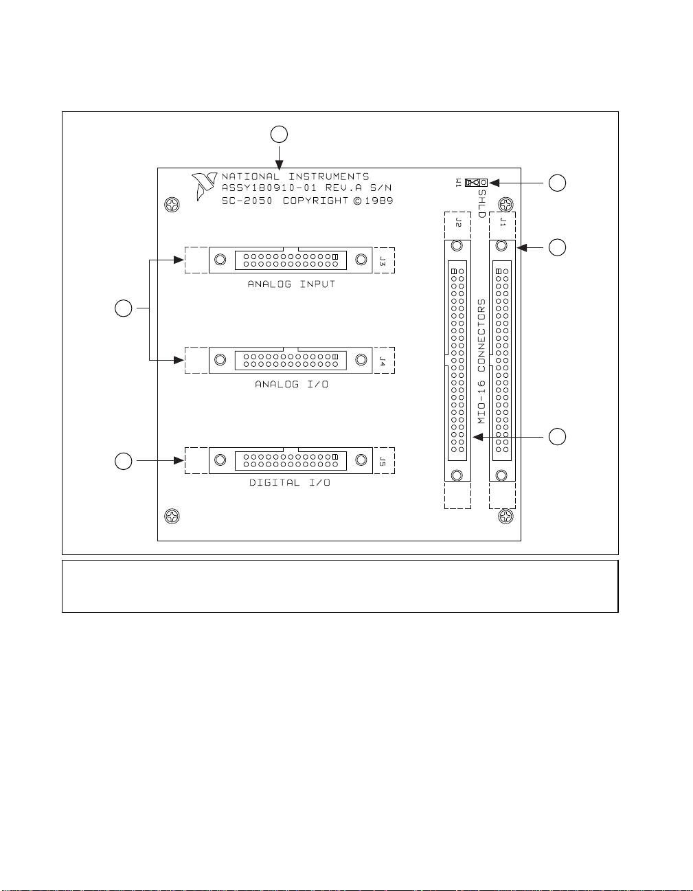
Figure 2-1 shows the SC-2050 parts locator diagram.
1
2
3
4
5
1 Product Name, Assembly Number, Revision Letter,
and Serial Number
2 Shield Jumper
3 To E Series device (MIO-16, etc.)
Figure 2-1. SC-2050 Parts Locator Diagram
SC-205X Series User Manual 2-2
4 To SC-207X, AMUX-64T, or CB-50
5 To SC-206X Series or SSR Series
6 To 5B Series
©
National Instruments Corporation
Page 20

SC-2050 Connection
Connect your SC-2050 to the DAQ device via an SH6850 cable or
PSHR68-50 cable (for DAQCards). Connect the SC-2050 to the 100-pin
AT-MIO-16DE-10 and PCI-6071E via a 100-pin R1005050 cable,
available separately. Make this connection with the host computer powered
off. Connect one end of the ribbon cable to the SC-2050 at either connector
J1 or J2. Connect the other end to the DAQ device installed in your
computer.
Chapter 2 SC-2050
Warning
Connectors
Do not connect the SC-2050 to a board for which it is not designed. Such
connection can damage the SC-2050 and any or all boards/accessories connected
NOT
to the SC-2050 and host computer. National instruments is
damages resulting from incorrect connections.
T o connect your SC-2050 to the signal conditioning accessories, use a type
NB7, 26-pin ribbon cable. This cable connects the SC-2050 to any of the
SC-206X Series boards or to the 5B Series backplane. An 8-channel SSR
Series backplane with a 26-conductor ribbon cable is also available for
connection to the SC-2050. For instructions on making these connections
to the proper signal conditioning accessories, refer to Cable Connections in
Chapter 10, Installation and Operation.
The SC-2050 has two 50-pin ribbon cable connectors that are connected
pin-by-pin to each other. You can use either of these connectors to attach
the SC-2050 to the DAQ device via a cable. You can daisy-chain the
second connector to other 50-pin accessories.
The SC-2050 also has three 26-pin ribbon cable connectors that you can use
to connect to the signal conditioning accessories. The analog ports have pin
connections that are compatible with the 5B Series of analog signal
conditioning modules. The digital ports are compatible with the SC-206X
Series digital signal conditioners as well as with the 8-channel SSR Series
solid-state relay board.
liable for any
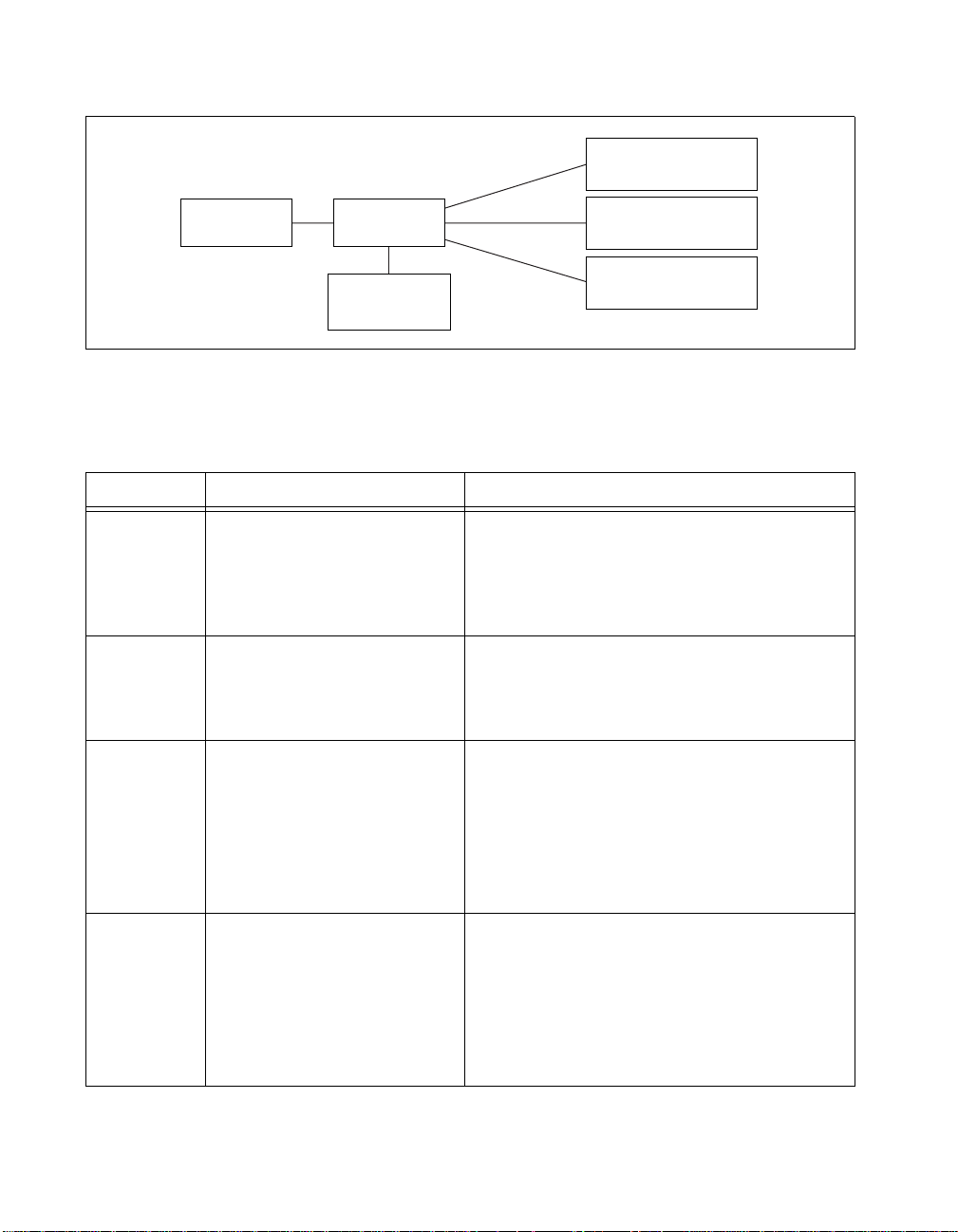
Figure 2-2 illustrates the connections between the SC-2050 and the
necessary accessories and devices.
©
National Instruments Corporation 2-3 SC-205X Series User Manual
Page 21
Chapter 2 SC-2050
J3
5B Series
E Series SC-2050
J1
J2
SC-2070,
AMUX-64T,
or CB-50
ANALOG INPUT
ANALOG I/O
DIGITAL I/O
Figure 2-2. SC-2050 Connections
J4
J5
5B Series
SC-206X Series or
8-Channel SSR Series
Table 2-1 describes the connectors on the SC-2050.
Table 2-1. SC-2050 Connectors
Connectors Connection Description
J1, J2 50-pin male ribbon cable
connectors; E Series
connection
J3 26-pin male connector; 5B
Series analog input connection
J4 26-pin male connector; 5B
Series analog I/O connection
J5 26-pin male connector; digital
I/O connection
Attach J1 or J2 to the DAQ device. The other
connector can attach to the SC-2070,
AMUX-64T , or CB-50. The connections at each
connector are identical so that you can
daisy-chain the E Series signals.
Attach J3 to the 5B Series backplane. This
connection takes analog input lines 0–15 on the
E Series to channels 0–15 of the 5B Series
backplane, in sequential order.
Attach J4 to the 5B Series backplane. This
connection takes analog input channels 0–13 on
the E Series to channels 0–3 of the 5B Series
backplane, in sequential order. It also connects
the voltage output signal DAC0OUT from the
E Series to channel 14 of the 5B Series and
DAC1OUT to channel 15.
Attach J5 to the SC-206X Series or SSR
8-channel boards. This connection takes the
eight digital I/O lines from the E Series to a
digital signal conditioning accessory with
compatible pin connections, such as the
SC-2060, SC-2061, SC-2062, or the 8-channel
SSR Series backplane.
SC-205X Series User Manual 2-4
©
National Instruments Corporation
Page 22
Chapter 2 SC-2050
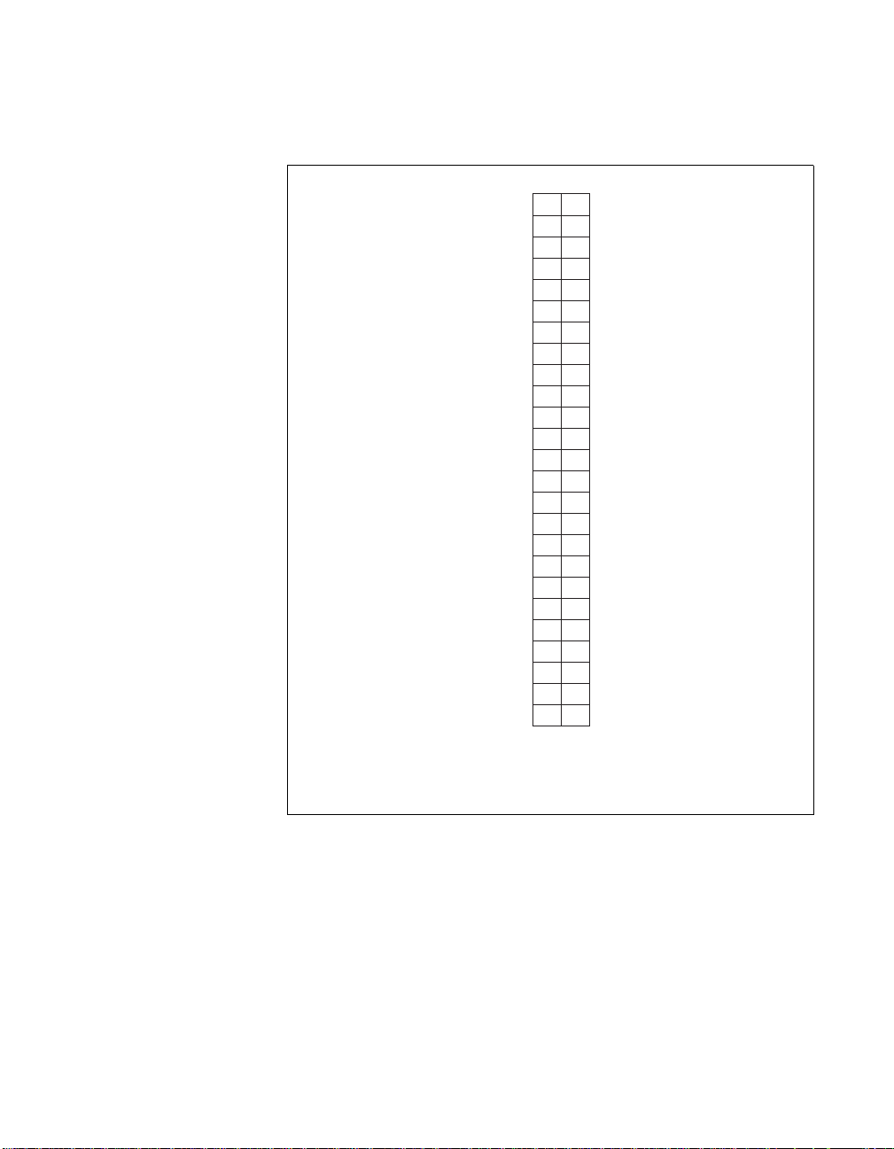
Figures 2-3 through 2-6 show the pin assignments for each I/O connector
on the SC-2050.
AIGND
ACH0
ACH1
ACH2
ACH3
ACH4
ACH5
ACH6
ACH7
AISENSE
DAC1OUT
AOGND
DIO0
DIO1
DIO2
DIO3
DGND
+5 V
EXSTROBE*
PFI1/TRIG2
PFI3/GPCTR1_SOURCE
GPCTR1_OUT
PFI6/WFTRIG
PFI8/GPCTR0_SOURCE
GPCTR0_OUT
1
12
34
56
78
910
11 12
13 14
15 16
17 18
19 20
21 22
23 24
25 26
27 28
29 30
31 32
33 34
35 36
37 38
39 40
41 42
43 44
45 46
47 48
49 50
AIGND
ACH8
ACH9
ACH10
ACH11
ACH12
ACH13
ACH14
ACH15
DAC0OUT
EXTREF
1
1
DGND
DIO4
DIO5
DIO6
DIO7
+5 V
SCANCLK
PFI0/TRIG1
PFI2/CONVERT*
PFI4/GPCTR1_GATE
PFI5/UPDATE*
PFI7/STARTSCAN
PFI9/GPCTR0_GATE
FREQ_OUT
1
Not available on all boards. Check your board's
documentation for these signals.
Figure 2-3. Pin Assignments for SC-2050 I/O Connectors J1 and J2
©
National Instruments Corporation 2-5 SC-205X Series User Manual
Page 23
Chapter 2 SC-2050
ACH0
AIGND
ACH1
ACH2
AIGND
ACH3
ACH4
AIGND
ACH5
ACH6
AIGND
ACH7
AISENSE
12
34
56
78
910
11 12
13 14
15 16
17 18
19 20
21 22
23 24
25 26
ACH8
ACH9
AIGND
ACH10
ACH11
AIGND
ACH12
ACH13
AIGND
ACH14
ACH15
AIGND
NC
Figure 2-4. Pin Assignments for SC-2050 Analog Input Connector J3
ACH0
AOGND
ACH1
ACH2
AOGND
ACH3
ACH4
AOGND
ACH5
ACH6
AOGND
ACH7
AISENSE
12
34
56
78
910
11 12
13 14
15 16
17 18
19 20
21 22
23 24
25 26
ACH8
ACH9
AOGND
ACH10
ACH11
AOGND
ACH12
ACH13
AOGND
DAC0OUT
DAC1OUT
AOGND
NC
Figure 2-5. Pin Assignments for SC-2050 Analog I/O Connector J4
SC-205X Series User Manual 2-6
©
National Instruments Corporation
Page 24
Chapter 2 SC-2050
Mounting
+5 V
+5 V
+5 V
+5 V
DIO7
DIO6
DIO5
DIO4
DIO3
DIO2
DIO1
DIO0
+5 V
12
34
56
78
910
11 12
13 14
15 16
17 18
19 20
21 22
23 24
25 26
GND
GND
GND
GND
GND
GND
GND
GND
GND
GND
GND
GND
GND
Figure 2-6. Pin Assignments for SC-2050 Digital I/O Connector J5
The SC-2050 adapter is equipped with metal standoffs so it can sit on a
workbench close to the host computer. A rack-mount chassis is also
available and can be fitted with a flat acrylic plastic cover, or a metal
wraparound cover. To ground the SC-2050 adapter to the chassis, set the
jumper on the adapter as described in Chapter 10, Installation and
Operation.
Cabling
You need a 50-pin ribbon cable to connect the SC-2050. Connections to the
SC-206X Series boards require a 26-pin ribbon cable. A 26-conductor
ribbon cable is needed for the 8-channel SSR backplane. Additional cables
are available from National Instruments for connection to other
accessories.
©
National Instruments Corporation 2-7 SC-205X Series User Manual
Page 25

SC-2051
3
This chapter describes the SC-2051 adapter in detail, including function,
connection, mounting, and cabling. Refer to Chapter 10, Installation and
Operation to install and use your adapter.
The SC-2051 converts 24 digital I/O signals to standard pin connections for
signal conditioning accessories. You can use the SC-2051 with DIO-24 and
6503 type devices. You can also use the SC-2051 with MIO devices having
24 additional digital channels, such as the AT-MIO-16DE-10. See
Table 1-1 for a complete list of DAQ devices that you can use with the
SC-2051.
©
National Instruments Corporation 3-1 SC-205X Series User Manual
Page 26
Chapter 3 SC-2051
5
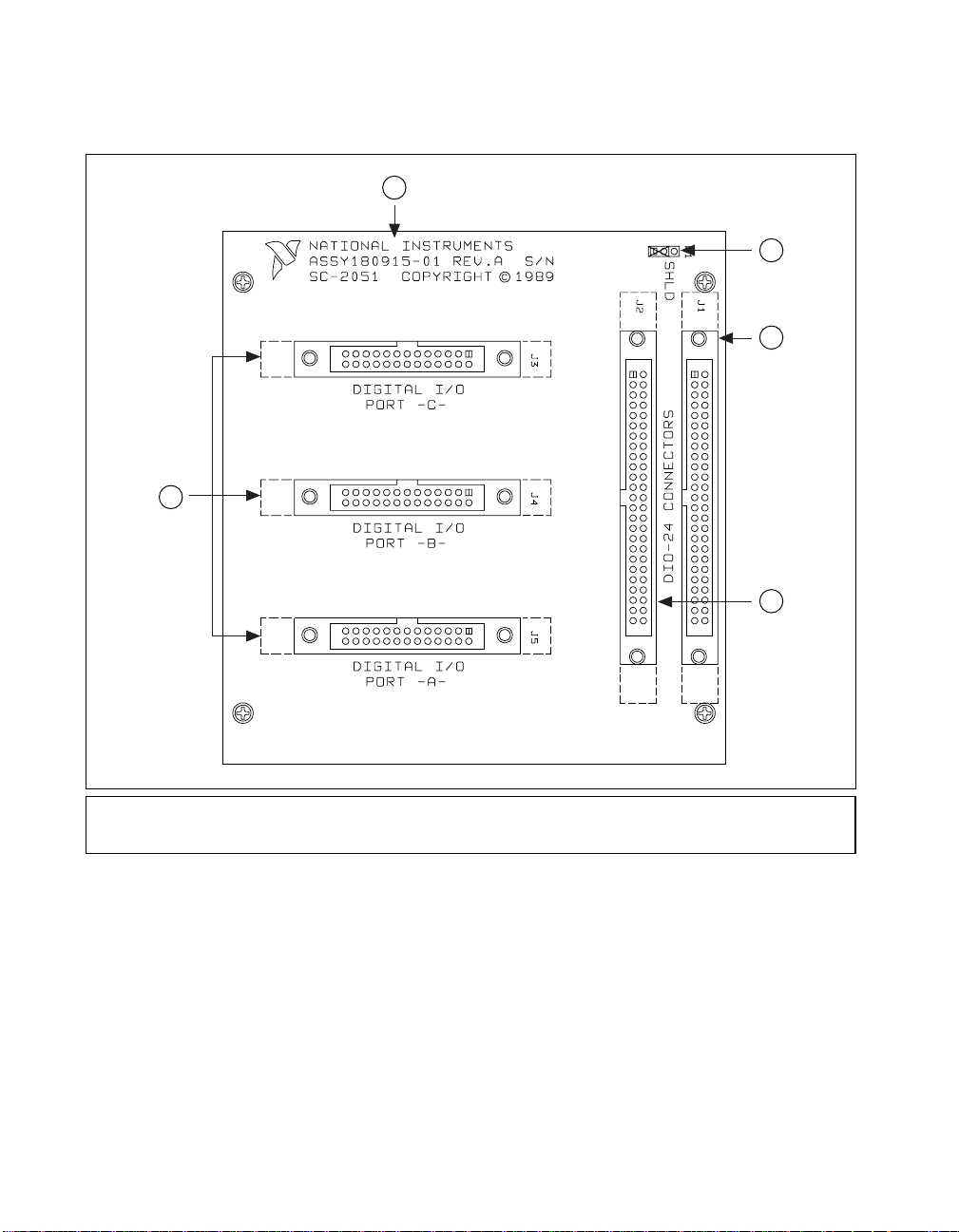
Figure 3-1 shows the SC-2051 parts locator diagram.
1
2
3
4
1 Product Name, Assembly Number, Revision Letter, and Serial Number
2 Shield Jumper
3 To DAQ device
Figure 3-1. SC-2051 Parts Locator Diagram
SC-205X Series User Manual 3-2
4 To CB-50
5 To SC-206X Series or SSR Series
©
National Instruments Corporation
Page 27

SC-2051 Connection
Connect your SC-2051 to a 50-pin DAQ board via a type NB1, 50-pin
ribbon cable. To connect the SC-2051 to the AT-MIO-16D or
AT-MIO-16DE-10, you will need a type NB5 cable; use a PR50-50F cable
for the DAQCard-DIO-24. Make this connection with the host computer
powered off. Connect one end of the ribbon cable to the SC-2051 at either
connector J1 or J2. Connect the other end to the DAQ device installed in
your computer.
Chapter 3 SC-2051
Warning
Connectors
Do not connect the SC-2051 to a board for which it is not designed. Such
connection can damage the SC-2051 and any or all boards/accessories connected
NOT
to the SC-2051 and host computer. National instruments is
damages resulting from incorrect connections.
T o connect your SC-2051 to the signal conditioning accessories, use a type
NB7, 26-pin ribbon cable. This cable connects the SC-2051 to any of the
SC-206X Series boards or to the 5B Series backplane. An 8-channel SSR
Series backplane with a 26-conductor ribbon cable is also available for
connection to the SC-2051. For instructions on making these connections
to the proper signal conditioning accessories, refer to Cable Connections in
Chapter 10, Installation and Operation.
The SC-2051 has two 50-pin ribbon cable connectors that are connected
pin-by-pin to each other. You can use either of these connectors to attach
the SC-2051 to the DAQ device via a cable. You can daisy-chain the
second connector to other 50-pin accessories.
The SC-2051 also has three 26-pin ribbon cable connectors that you can use
to connect to the signal conditioning accessories. The digital ports are
compatible with the SC-206X Series digital signal conditioners as well as
with the 8-channel SSR Series solid-state relay board.
liable for any
©
National Instruments Corporation 3-3 SC-205X Series User Manual
Page 28
Chapter 3 SC-2051
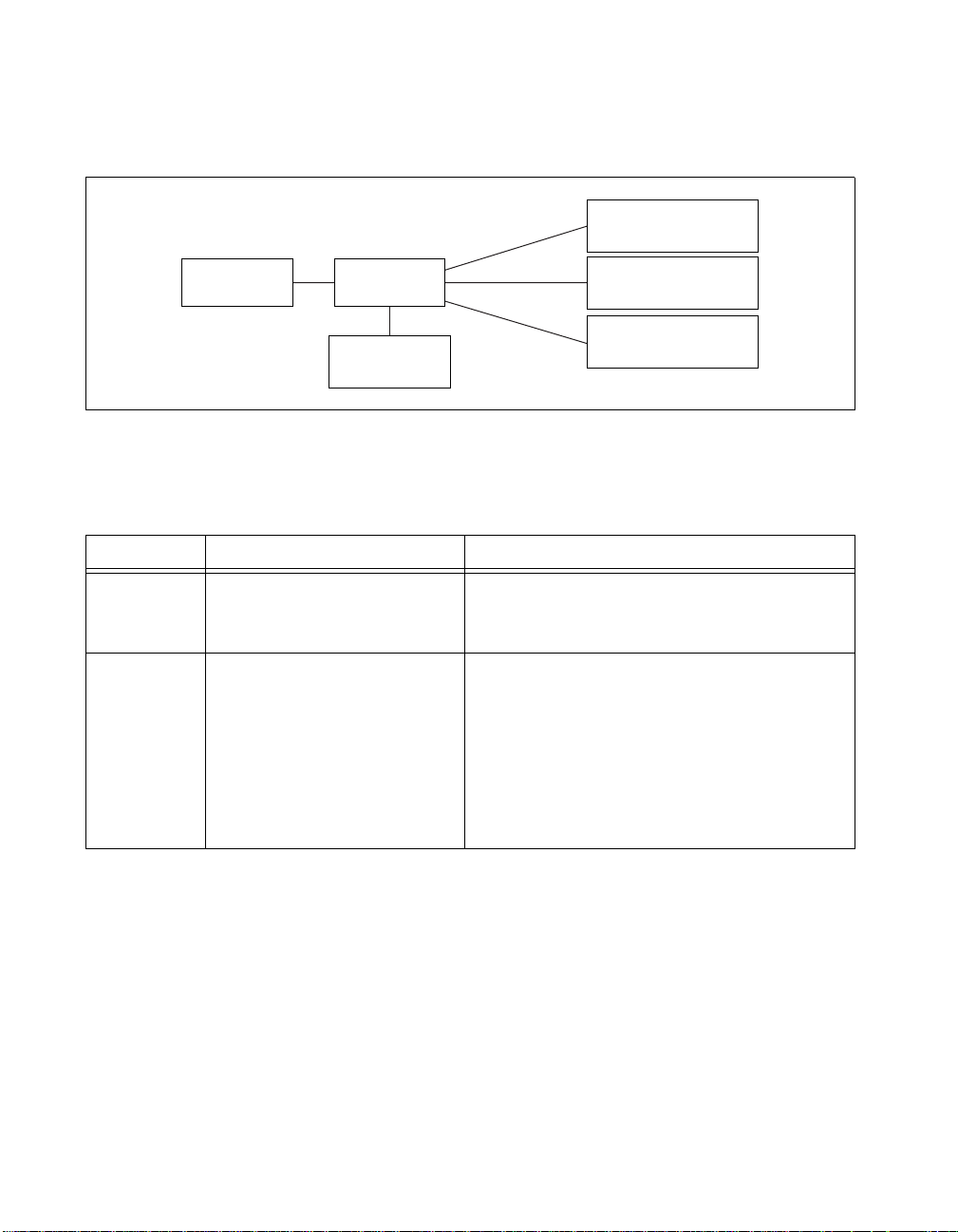
Figure 3-2 illustrates the connections between the SC-2051 and the
necessary accessories and devices.
J3
SC-206X Series or
8-Channel SSR Series
DIO-24 or 6503
J1
SC-2051
J2
CB-50
PORT C
BTROP
PORT A
Figure 3-2. SC-2051 Connections
J4
SC-206X Series or
8-Channel SSR Series
J5
SC-206X Series or
8-Channel SSR Series
Table 3-1 describes the connectors on the SC-2051.
Table 3-1. SC-2051 Connectors
Connectors Connection Description
J1, J2 50-pin male connectors; 24
DIO channel connection
J3
26-pin male connector; port C,
or 2, digital I/O connection
J4
26-pin male connector; port B,
or 1, digital I/O connection
J5
26-pin male connector; port A,
or 0, digital I/O connection
Attach J1 or J2 to the DAQ device. The other
connector can daisy-chain the board signals to
other 50-pin accessories such as a CB-50.
Attach each of these connectors to an SC-206X
Series board or to an 8-channel SSR Series
backplane. Connect the eight digital lines of the
port corresponding to the label below the
connector to the digital lines of the accessory.
SC-205X Series User Manual 3-4
©
National Instruments Corporation
Page 29
Chapter 3 SC-2051
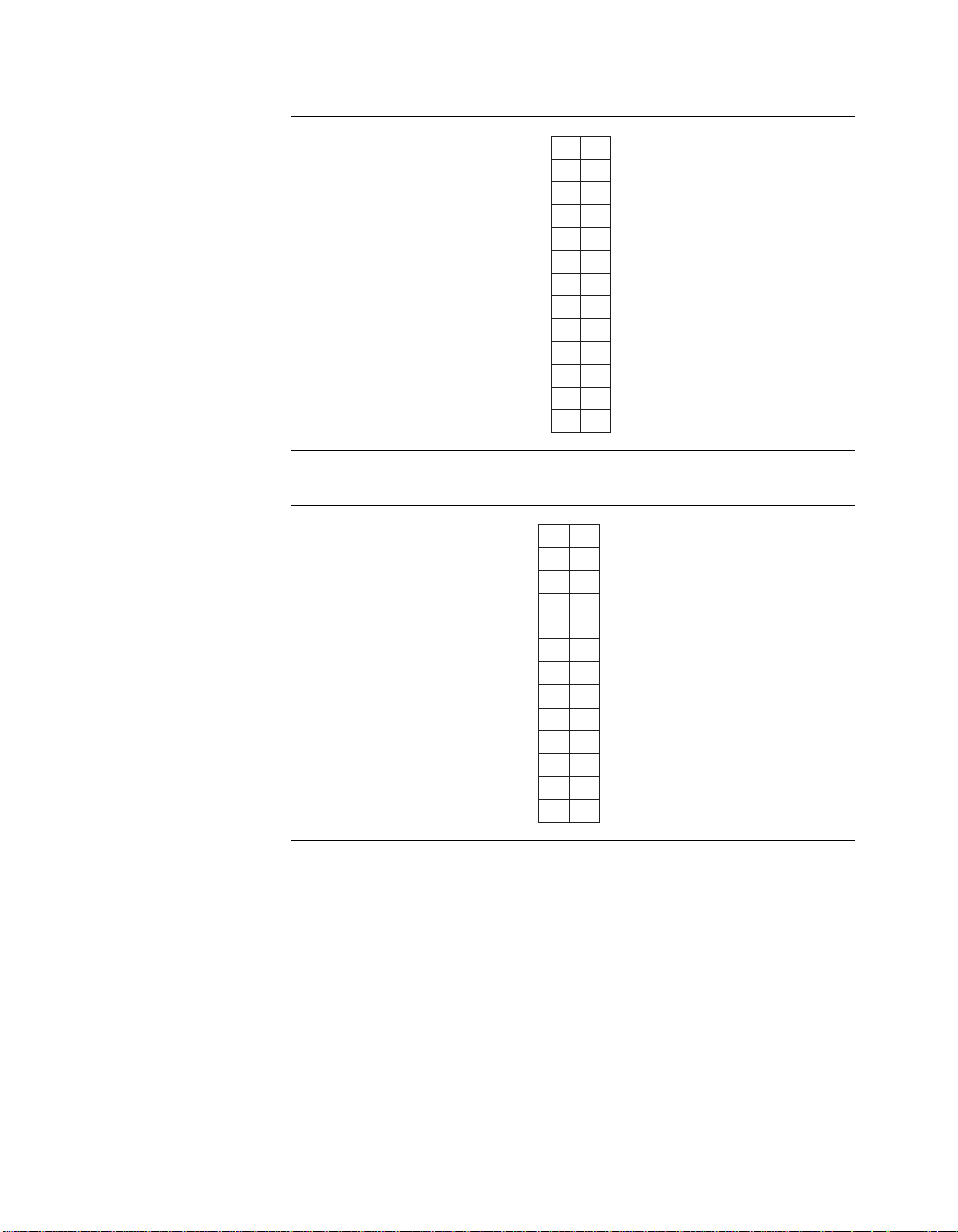
Figures 3-3 through 3-6 show the pin assignments for each I/O connector
on the SC-2051.
12
PC7
PC6
PC5
PC4
PC3
PC2
PC1
PC0
PB7
PB6
PB5
PB4
PB3
PB2
PB1
PB0
PA7
PA6
PA5
PA4
PA3
PA2
PA1
PA0
+5 V
34
56
78
910
11 12
13 14
15 16
17 18
19 20
21 22
23 24
25 26
27 28
29 30
31 32
33 34
35 36
37 38
39 40
41 42
43 44
45 46
47 48
49 50
GND
GND
GND
GND
GND
GND
GND
GND
GND
GND
GND
GND
GND
GND
GND
GND
GND
GND
GND
GND
GND
GND
GND
GND
GND
Figure 3-3. Pin Assignments for SC-2051 I/O Connectors J1 and J2
©
National Instruments Corporation 3-5 SC-205X Series User Manual
Page 30

Chapter 3 SC-2051
+5 V
+5 V
+5 V
+5 V
PC7
PC6
PC5
PC4
PC3
PC2
PC1
PC0
+5 V
12
34
56
78
910
11 12
13 14
15 16
17 18
19 20
21 22
23 24
25 26
GND
GND
GND
GND
GND
GND
GND
GND
GND
GND
GND
GND
GND
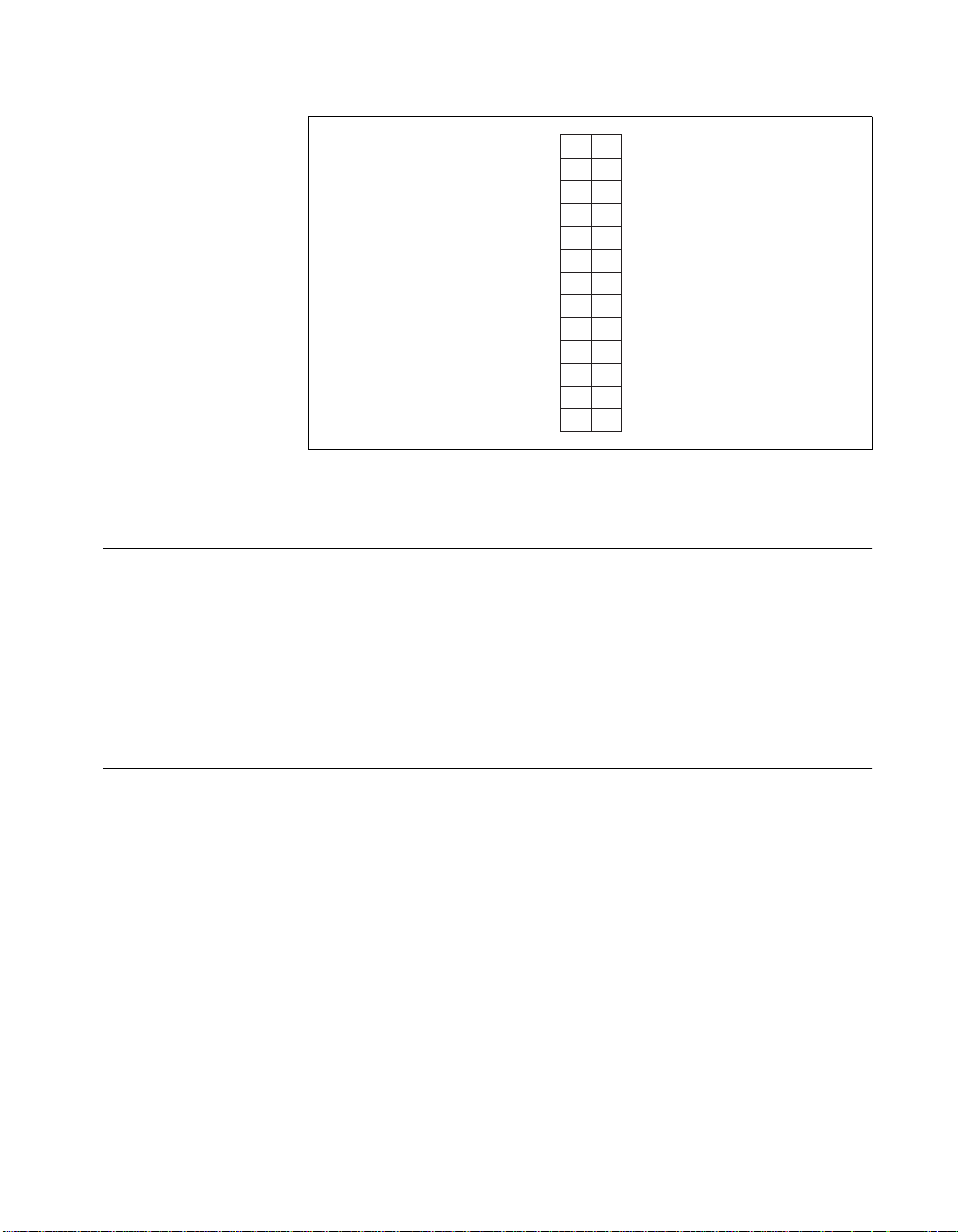
Figure 3-4. Pin Assignments for SC-2051 I/O Connector J3
PB7
PB6
PB5
PB4
PB3
PB2
PB1
PB0
12
34
56
78
910
11 12
13 14
15 16
17 18
19 20
21 22
23 24
25 26
GND
GND
GND
GND
GND
GND
GND
GND
GND
GND
GND
GND
GND
+5 V
+5 V
+5 V
+5 V
+5 V
Figure 3-5. Pin Assignments for SC-2051 I/O Connector J4
SC-205X Series User Manual 3-6
©
National Instruments Corporation
Page 31

Chapter 3 SC-2051
Mounting
PA7
PA6
PA5
PA4
PA3
PA2
PA1
PA0
12
34
56
78
910
11 12
13 14
15 16
17 18
19 20
21 22
23 24
25 26
GND
GND
GND
GND
GND
GND
GND
GND
GND
GND
GND
GND
GND
+5 V
+5 V
+5 V
+5 V
+5 V
Figure 3-6. Pin Assignments for SC-2051 I/O Connector J5
The SC-2051 adapter is equipped with metal standoffs so it can sit on a
workbench close to the host computer. A rack-mount is also available and
can be fitted with a flat acrylic plastic cover or metal wraparound cover. To
ground the SC-2051 adapter to the chassis, set the jumper on the adapter as
described in Chapter 10, Installation and Operation.
Cabling
You need a 50-pin ribbon cable to connect the SC-2051 to a DAQ device;
the cable needed depends on the DAQ device. Connections to the SC-206X
Series boards require a 26-pin ribbon cable. A 26-conductor ribbon cable is
needed for the 8-channel SSR backplane. Additional cables are available
from National Instruments for connection to other accessories.
©
National Instruments Corporation 3-7 SC-205X Series User Manual
Page 32

SC-2052
4
This chapter describes the SC-2052 adapter in detail, including function,
connection, mounting, and cabling. Refer to Chapter 10, Installation and
Operation to install and use your adapter.
The SC-2052 converts 32 digital I/O signals to standard pin connections for
signal conditioning accessories. You can use the SC-2052 with DIO-32 and
6533 type devices. See Table 1-1 for a complete list of DAQ devices that
you can use with the SC-2052.
©
National Instruments Corporation 4-1 SC-205X Series User Manual
Page 33

Chapter 4 SC-2052
5
Figure 4-1 shows the SC-2052 parts locator diagram.
1
2
3
1 Product Name, Assembly Number, Revision Letter, and Serial Number
2 Shield Jumper
3 To DIO-32 and 6533 devices
Figure 4-1. SC-2052 Parts Locator Diagram
4 To CB-50
5 To SC-206
4
X
Series or SSR Series
SC-205X Series User Manual 4-2
©
National Instruments Corporation
Page 34

SC-2052 Connection
Connect your SC-2052 to the DAQ device via an R6850-D1 or a type NB1,
50-pin ribbon cable (for the AT-DIO-32F). Make this connection with the
host computer powered off. Connect one end of the ribbon cable to the
SC-2052 at either connector J1 or J2. Connect the other end to the DAQ
device installed in your computer.
Chapter 4 SC-2052
Warning
Connectors
Do not connect the SC-2052 to a board for which it is not designed. Such
connection can damage the SC-2052 and any or all boards/accessories connected
NOT
to the SC-2052 and the host computer. National instruments is
damages resulting from incorrect connections.
T o connect your SC-2052 to the signal conditioning accessories, use a type
NB7, 26-pin ribbon cable. This cable connects the SC-2052 to any of the
SC-206X Series boards. An 8-channel SSR Series backplane with a
26-conductor ribbon cable is also available for connection to the SC-2052.
For instructions on making these connections to the proper signal
conditioning accessories, refer to Cable Connections in Chapter 10,
Installation and Operation.
The SC-2052 has two 50-pin ribbon cable connectors that are connected
pin-by-pin to each other. You can use either of these connectors to attach
the SC-2052 to the DAQ device via a cable. You can daisy-chain the
second connector to other 50-pin accessories.
The SC-2052 also has four 26-pin ribbon cable connectors that you can
connect to the signal conditioning accessories. The digital ports are
compatible with the SC-206X Series digital signal conditioners as well as
with the 8-channel SSR Series solid-state relay board.
liable for any
The SC-2052 has 2-pin screw terminals which are connected to auxiliary
digital input lines and digital output lines of the DAQ device. You can use
these screw terminals to attach these lines to appropriate external circuitry .
Figure 4-2 illustrates the connections between the SC-2052 and the
necessary accessories and devices.
©
National Instruments Corporation 4-3 SC-205X Series User Manual
Page 35

Chapter 4 SC-2052
DIO-32 or 6533 SC-2052
J1
J2
CB-50
Digital I/O
PORT D
PORT C
PORT B
PORT A
J3
SC-206X Series or
8-Channel SSR Series
J4
SC-206X Series or
8-Channel SSR Series
J5
SC-206X Series or
8-Channel SSR Series
J6
SC-206X Series or
8-Channel SSR Series
Figure 4-2. SC-2052 Connections
Table 4-1 describes the connectors on the SC-2052.
Table 4-1. SC-2052 Connectors
Connectors Connection Description
J1, J2 50-pin male connectors; DIO-32,
6533 connection
J3
J4
26-pin male connectors; port D, or 3,
digital I/O connection
26-pin male connectors; port C, or 2,
digital I/O connection
Attach J1 or J2 to the DAQ device. The other connector can
daisy-chain the DA Q device signals to other 50-pin accessories
such as a CB-50.
You can attach each of these connectors to an SC-206X Series
board or to an 8
J4, J5, and J6 connect the eight digital lines of the port
corresponding to the label below the connector to the digital
lines of the accessory.
-
channel SSR Series backplane. Connectors J3,
J5
J6
J7
J8
J9
26-pin male connectors; port B, or 1,
digital I/O connection
26-pin male connectors; port A, or 0,
digital I/O connection
Two-position screw terminal block;
grounded
Two-position screw terminal block;
digital lines STOPTRIG2 (IN2) and
PCLK2 (OUT2)
Two-position screw terminal block;
digital lines STOPTRIG1 (IN1) and
PCLK1(OUT1)
Screw terminals J8 and J9 are connected to the two auxiliary
digital input lines STOPTRIG1 (IN1) and STOPTRIG2 (IN2)
and two auxiliary digital output lines PCLK1(OUT1) and
PCLK2 (OUT2) of your DAQ de vice. You can insert wires in
the screw terminals to attach these lines to appropriate external
circuitry. Consult the user manual for your DAQ device for
further details on the correct connection of these
SC-205X Series User Manual 4-4
lines.
©
National Instruments Corporation
Page 36

Chapter 4 SC-2052
Figures 4-3 through 4-7 show the pin assignments for each I/O connector
on the SC-2052.
DIOD1
DIOD3
DIOD6
DIOD2
DIOC5
DIOC3
DIOC2
DIOC6
GND
GND
GND
GND
GND
ACK1
STOPTRIG1 (IN1)
PCLK1 (OUT1)
REQ1
DIOA4
DIOA0
DIOA1
DIOA7
DIOB5
DIOB7
DIOB0
DIOB4
12
34
56
78
910
11 12
13 14
15 16
17 18
19 20
21 22
23 24
25 26
27 28
29 30
31 32
33 34
35 36
37 38
39 40
41 42
43 44
45 46
47 48
49 50
DIOD4
DIOD0
DIOD7
DIOD5
DIOC7
DIOC1
DIOC0
DIOC4
ACK2
STOPTRIG2 (IN2)
PCLK2 (OUT2)
REQ2
GND
GND
GND
GND
GND
DIOA6
DIOA2
DIOA3
DIOA5
DIOB2
DIOB6
DIOB3
DIOB1
Figure 4-3. Pin Assignments for SC-2052 I/O Connectors J1 and J2
©
National Instruments Corporation 4-5 SC-205X Series User Manual
Page 37

Chapter 4 SC-2052
12
NC
NC
NC
NC
DIOD7
DIOD6
DIOD5
DIOD4
DIOD3
DIOD2
DIOD1
DIOD0
NC
34
56
78
910
11 12
13 14
15 16
17 18
19 20
21 22
23 24
25 26
GND
GND
GND
GND
GND
GND
GND
GND
GND
GND
GND
GND
GND
Figure 4-4. Pin Assignments for SC-2052 I/O Connector J3
12
NC
NC
NC
NC
DIOC7
DIOC6
DIOC5
DIOC4
DIOC3
DIOC2
DIOC1
DIOC0
NC
34
56
78
910
11 12
13 14
15 16
17 18
19 20
21 22
23 24
25 26
GND
GND
GND
GND
GND
GND
GND
GND
GND
GND
GND
GND
GND
Figure 4-5. Pin Assignments for SC-2052 I/O Connector J4
SC-205X Series User Manual 4-6
©
National Instruments Corporation
Page 38

Chapter 4 SC-2052
12
NC
NC
NC
NC
DIOB7
DIOB6
DIOB5
DIOB4
DIOB3
DIOB2
DIOB1
DIOB0
NC
34
56
78
910
11 12
13 14
15 16
17 18
19 20
21 22
23 24
25 26
GND
GND
GND
GND
GND
GND
GND
GND
GND
GND
GND
GND
GND
Figure 4-6. Pin Assignments for SC-2052 I/O Connector J5
12
NC
NC
NC
NC
DIOA7
DIOA6
DIOA5
DIOA4
DIOA3
DIOA2
DIOA1
DIOA0
NC
34
56
78
910
11 12
13 14
15 16
17 18
19 20
21 22
23 24
25 26
GND
GND
GND
GND
GND
GND
GND
GND
GND
GND
GND
GND
GND
Figure 4-7. Pin Assignments for SC-2052 I/O Connector J6
Mounting
The SC-2052 adapter is equipped with metal standoffs so it can sit on a
workbench close to the host computer. A rack-mount is also available and
can be fitted with a flat acrylic plastic cover or metal wraparound cover. To
ground the SC-2052 adapter to the chassis, set the jumper on the adapter as
described in Chapter 10, Installation and Operation.
©
National Instruments Corporation 4-7 SC-205X Series User Manual
Page 39

Chapter 4 SC-2052
Cabling
You need an R6850-D1 ribbon cable to connect the SC-2052 to a 68-pin
DAQ device. Connections to the SC-206X Series boards require a 26-pin
ribbon cable. A 26-conductor ribbon cable is needed for the 8-channel SSR
backplane. Additional cables are available from National Instruments for
connection to other accessories.
SC-205X Series User Manual 4-8
©
National Instruments Corporation
Page 40

SC-2053
5
This chapter describes the SC-2053 adapter in detail, including function,
connection, mounting, and cabling. Refer to Chapter 10, Installation and
Operation to install and use your adapter.
The SC-2053 converts the Lab/1200 Series board I/O connector signals to
standard pin connections for signal conditioning accessories. You can use
the SC-2053 with the Lab/1200 devices. See Table 1-1 for a complete list
of DAQ devices that you can use with the SC-2053.
©
National Instruments Corporation 5-1 SC-205X Series User Manual
Page 41

Chapter 5 SC-2053
6
5
Figure 5-1 shows the SC-2053 parts locator diagram.
1
2
3
1 Product Name, Assembly Number, Revision Letter, and Serial Number
2 Shield Jumper
3 To Lab-NB, Lab-PC, or 1200 device
Figure 5-1. SC-2053 Parts Locator Diagram
4 To CB-50 or SC-2701
5 To SC-206
6 To 5B Series
X
Series or SSR Series
4
SC-205X Series User Manual 5-2
©
National Instruments Corporation
Page 42

SC-2053 Connection
Connect your SC-2053 to the DAQ device via a type NB1, 50-pin ribbon
cable. Make this connection with the host computer powered off. Connect
one end of the ribbon cable to the SC-2053 at either connector J1 or J2.
Connect the other end to the DAQ device installed in your computer or to
the DAQPad-1200.
Chapter 5 SC-2053
Warning
Connectors
Do not connect the SC-2053 to a board for which it is not designed. Such
connection can damage the SC-2053 and any or all boards/accessories connected
NOT
to the SC-2053, and host computer. National instruments is
damages resulting from incorrect connections.
T o connect your SC-2053 to the signal conditioning accessories, use a type
NB7, 26-pin ribbon cable. This cable connects the SC-2053 to any of the
SC-206X Series boards or to the 5B Series backplane. An 8-channel SSR
Series backplane with a 26-conductor ribbon cable is also available for
connection to the SC-2053. For instructions on making these connections
to the proper signal conditioning accessories, refer to Cable Connections in
Chapter 10, Installation and Operation.
The SC-2053 has two 50-pin ribbon cable connectors that are connected
pin-by-pin to each other. You can use either of these connectors to attach
the SC-2053 to the DAQ device via a cable. You can daisy-chain the
second connector to other 50-pin accessories.
The SC-2053 also has four 26-pin ribbon cable connectors that you can use
to connect to the signal conditioning accessories. The analog ports have pin
connections that are compatible with the 5B Series of analog signal
conditioning modules. The digital ports are compatible with the SC-206X
Series digital signal conditioners as well as with the 8-channel SSR Series
solid-state relay board.
liable for any
Figure 5-2 illustrates the connections between the SC-2053 and the
necessary accessories and devices.
©
National Instruments Corporation 5-3 SC-205X Series User Manual
Page 43

Chapter 5 SC-2053
Lab/1200 SC-2053
J1
J2
SC-2071
or CB-50
Analog I/O
Digital I/O
PORT A
PORT C
Figure 5-2. SC-2053 Connections
J3
J4
J5
BTROP
J6
5B Series
SC-206X Series or
8-Channel SSR Series
SC-206X Series or
8-Channel SSR Series
SC-206X Series or
8-Channel SSR Series
Table 5-1 describes the connectors on the SC-2053.
Table 5-1. SC-2053 Connectors
Connectors Connection Description
J1, J2 50-pin male connectors;
Lab/1200 connection
Attach J1 or J2 to the DAQ device. The other
connector can daisy-chain the DAQ device
signals to other 50-pin accessories such as a
CB-50 or SC-2071.
J3 26-pin male connector; 5B
Series analog I/O connection
Attach J3 to the 5B Series backplane. This
connection takes analog input channels 0–7 on
the DA Q de vice to channels 0–7 of the 5B Series
backplane in sequential order. The voltage output
signal DAC0OUT from the DAQ device is
connected to channel 8 of the 5B Series and
DAC1OUT is connected to channel 9.
J4
26-pin male connector; port A
digital I/O connection
J5
26-pin male connector; port B
digital I/O connection
J6
26-pin male connector; port C
digital I/O connection
SC-205X Series User Manual 5-4
Attach each of these connectors to an SC-206X
Series board or to an 8-channel SSR Series
backplane. Connectors J4, J5, and J6 connect the
eight digital lines of the port corresponding to the
label below the connector to the digital lines of
the accessory .
©
National Instruments Corporation
Page 44

Chapter 5 SC-2053
Figures 5-3 through 5-7 show the pin assignments for each I/O connector
on the SC-2053.
ACH0
ACH2
ACH4
ACH6
AIGND
AOGND
DGND
PA1
PA3
PA5
PA7
PB1
PB3
PB5
PB7
PC1
PC3
PC5
PC7
EXTUPDATE
OUT0
OUT1
CLK1
GAT2
+5 V
12
34
56
78
910
11 12
13 14
15 16
17 18
19 20
21 22
23 24
25 26
27 28
29 30
31 32
33 34
35 36
37 38
39 40
41 42
43 44
45 46
47 48
49 50
ACH1
ACH3
ACH5
ACH7
DAC0OUT
DAC1OUT
PA0
PA2
PA4
PA6
PB0
PB2
PB4
PB6
PC0
PC2
PC4
PC6
EXTRIG
EXTCONV
GAT0
GAT1
OUT2
CLK2
DGND
Figure 5-3. Pin Assignments for SC-2053 I/0 Connectors J1 and J2
©
National Instruments Corporation 5-5 SC-205X Series User Manual
Page 45

Chapter 5 SC-2053
ACH0
AOGND
ACH1
ACH2
AIGND
ACH3
ACH4
AOGND
ACH5
ACH6
AOGND
ACH7
AISENSE
12
34
56
78
910
11 12
13 14
15 16
17 18
19 20
21 22
23 24
25 26
DAC0OUT
DAC1OUT
AOGND
NC
NC
AOGND
NC
NC
AOGND
NC
NC
AOGND
NC
Figure 5-4. Pin Assignments for SC-2053 I/O Connector J3
PA7
PA6
PA5
PA4
PA3
PA2
PA1
PA0
12
34
56
78
910
11 12
13 14
15 16
17 18
19 20
21 22
23 24
25 26
GND
GND
GND
GND
GND
GND
GND
GND
GND
GND
GND
GND
GND
+5 V
+5 V
+5 V
+5 V
+5 V
Figure 5-5. Pin Assignments for SC-2053 I/O Connector J4
SC-205X Series User Manual 5-6
©
National Instruments Corporation
Page 46

Chapter 5 SC-2053
PB7
PB6
PB5
PB4
PB3
PB2
PB1
PB0
12
34
56
78
910
11 12
13 14
15 16
17 18
19 20
21 22
23 24
25 26
GND
GND
GND
GND
GND
GND
GND
GND
GND
GND
GND
GND
GND
+5 V
+5 V
+5 V
+5 V
+5 V
Figure 5-6. Pin Assignments for SC-2053 I/O Connector J5
+5 V
+5 V
+5 V
+5 V
PC7
PC6
PC5
PC4
PC3
PC2
PC1
PC0
+5 V
12
34
56
78
910
11 12
13 14
15 16
17 18
19 20
21 22
23 24
25 26
GND
GND
GND
GND
GND
GND
GND
GND
GND
GND
GND
GND
GND
Figure 5-7. Pin Assignments for SC-2053 I/O Connector J6
Mounting
The SC-2053 adapter is equipped with metal standoffs so it can sit on a
workbench close to the host computer. A rack-mount chassis is also
available and can be fitted with a flat acrylic plastic cover or metal
wraparound cover. To ground the SC-2053 adapter to the chassis, set the
jumper on the adapter as described in Chapter 10, Installation and
Operation.
©
National Instruments Corporation 5-7 SC-205X Series User Manual
Page 47

Chapter 5 SC-2053
Cabling
You need a 50-pin ribbon cable to connect the SC-2053. Connections to the
SC-206X Series boards and 5B Series backplane require a 26-pin ribbon
cable. A 26-conductor ribbon cable is needed for the 8-channel SSR
backplane. Additional cables are available from National Instruments for
connection to other accessories.
SC-205X Series User Manual 5-8
©
National Instruments Corporation
Page 48

SC-2054
6
This chapter describes the SC-2054 adapter in detail, including function,
connection, mounting, and cabling. Refer to Chapter 10, Installation and
Operation to install and use your adapter.
The SC-2054 converts half of the 96 digital I/O connector signals from a 96
digital channel device to standard pin connections for signal conditioning
accessories.
Y ou can use the SC-2054 with DIO-96 and 6508 devices. The SC-2054 also
works with DIO-24 devices; however, the SC-2051 is a more appropriate
solution. See T able 1-1 for a complete list of DA Q devices that you can use
with the SC-2054.
©
National Instruments Corporation 6-1 SC-205X Series User Manual
Page 49

Chapter 6 SC-2054
3
Figure 6-1 shows the SC-2054 parts locator diagram.
4 5
6
12
1 Product Name, Assembly Number, Revision Letter, and Serial
Number
2 Shield Jumper
3 To DAQ Device
4 To CB-50
5 To 16-Channel or 24-Channel SSR
6To SC-206
SSR
Figure 6-1. SC-2054 Parts Locator Diagram
SC-2054 Connection
Your SC-2054 is connected to the 96-channel DAQ device via a type NB5,
100-pin ribbon cable or R1005050 ribbon cable depending on the device.
Make this connection with the host computer powered off. Connect one of
the 50-pin connector ends of the cable to the SC-2054 at connector J1.
Connect the 100-pin connector end of the cable to the DAQ device installed
in your computer.
Warning Do not connect the SC-2054 to a board for which it is not designed. Such
connection can damage the SC-2054 and any or all boards/accessories connected
to the SC-2054 and host computer. National instruments is
damages resulting from incorrect connections.
SC-205X Series User Manual 6-2
©
National Instruments Corporation
X
Series or 8-Channel
NOT
liable for any
Page 50

Connectors
Chapter 6 SC-2054
Connect your SC-2054 to the signal conditioning accessories via a type
NB7, 26-pin ribbon cable. This cable connects the SC-2054 to any of the
SC-206X Series boards. An 8-channel SSR Series backplane with a
26-conductor ribbon cable is available for connection to the SC-2054.
A 50-pin cable is also available to connect the SC-2054 to a 16-channel or
24-channel SSR Series backplane. For instructions on making these
connections to the proper signal conditioning accessories, refer to Cable
Connections in Chapter 10, Installation and Operation.
The SC-2054 has four 50-pin ribbon cable connectors. The first two are
connected pin-by-pin to each other. You can use either of the first two
connectors to attach the SC-2054 to the DAQ device via a type NB5 or
R1005050 cable. You can daisy-chain the second connector to 48-channel
digital I/O signals and other 50-pin accessories. Each of the other two
50-pin connectors has 24-channel digital I/O signals in a DIO-24-style
connector.
The SC-2054 also has six 26-pin ribbon cable connectors that you can use
to connect to the signal conditioning accessories. The digital ports are
compatible with the SC-206X Series digital signal conditioners as well as
with the 8-channel SSR Series solid-state relay board.
Figure 6-2 illustrates the connections between the SC-2054 and the
necessary accessories and devices.
Note
A single SC-2054 adapter has signal-conditioning compatible pin connections for
only half of the signals on a 96-channel DAQ device. Two SC-2054 adapters with
a type NB5 or R1005050 cable have signal-conditioning compatible pin
connections for all 96 signals on the DAQ device.
©
National Instruments Corporation 6-3 SC-205X Series User Manual
Page 51

Chapter 6 SC-2054
DIO-96 or 6508
J1 or J2
J1 or J2
Type NB5 Cable
or R1005050
CB-50
SC-2054
PPI A/C
SC-2054
PPI B/D
J3/J7
CB-50,
16-Channel or
24-Channel
SSR Series
Port C
J4
Port B
J5
Port A
J6
Port C
J8
Port B
J9
Port A
J10
SC-206X Series or
8-Channel SSR Series
SC-206X Series or
8-Channel SSR Series
SC-206X Series or
8-Channel SSR Series
SC-206X Series or
8-Channel SSR Series
SC-206X Series or
8-Channel SSR Series
SC-206X Series or
8-Channel SSR Series
Figure 6-2. SC-2054 Connections
Table 6-1 describes the connectors on the SC-2054.
Table 6-1. SC-2054 Connectors
Connectors Connection Description
J1, J2 50-pin male connectors Attach J1 or J2 to the DA Q device via a type NB5
or R1005050 cable. The other connector can
daisy-chain the 48-channel digital I/O signals to
other 50-pin accessories such as a CB-50.
J3, J7 50-pin male connectors
J3 is tied to PPI A (ports 0 to 2)
or PPI C (ports 6 to 8),
depending on which half of the
type NB5 or R1005050 cable is
attached to J1. J7 is tied to
PPI B (ports 3 to 5) or PPI D
(ports 9 to 11), depending on
which half of the type NB5
cable is attached to J1.
SC-205X Series User Manual 6-4
Connect J3 or J7 to any DIO-24 accessories or
daisy-chain the 24-channel digital I/O signals to
other 50-pin accessories such as a CB-50 or a
16-channel or 24-channel SSR Series board.
©
National Instruments Corporation
Page 52

Table 6-1. SC-2054 Connectors (Continued)
Connectors Connection Description
Chapter 6 SC-2054
J4, J8 26-pin male connectors
Port C digital I/O connection.
J4 is tied to port C of PPI A or
C (port number 2 or 8),
depending on which half of the
type NB5 cable is attached to
J1. J8 is tied to port C of PPI B
or D (port number 5 or 11),
depending on which half of the
type NB5 cable is attached to
J1.
J5, J9 26-pin male connectors
Port B digital I/O connection.
J5 is tied to port B of PPI A or
C (port number 1 or 7),
depending on which half of the
type NB5 cable is attached to
J1. J9 is tied to port B of PPI B
or D (port number 4 or 10),
depending on which half of the
type NB5 cable is attached to
J1.
Attach J4 or J8 connectors to an SC-206X Series
-
board or to an 8
channel SSR Series backplane.
The eight digital lines of the port corresponding
to the label below the connector are connected to
the digital lines of the accessory.
Attach J5 or J9 connectors to an SC-206X Series
-
board or to an 8
channel SSR Series backplane.
The eight digital lines of the port corresponding
to the label below the connector are connected to
the digital lines of the accessory.
J6, J10 26-pin male connectors
Port A digital I/O connection.
J6 is tied to port A of PPI A or
C (port number 0 or 6),
Attach J6 or J10 connectors to an SC-206X
-
Series board or to an 8
channel SSR Series
backplane. The eight digital lines of the port
corresponding to the label below the connector
are connected to the digital lines of the accessory.
depending on which half of the
type NB5 cable is attached to
J1. J10 is tied to port A of
PPI B or D (port number 3 or
9), depending on which half of
the type NB5 cable is attached
to J1.
©
National Instruments Corporation 6-5 SC-205X Series User Manual
Page 53

Chapter 6 SC-2054
Figures 6-3 through 6-7 show the pin assignments for each I/O connector
on the SC-2054.
APC7
APC6
APC5
APC4
APC3
APC2
APC1
APC0
APB7
APB6
APB5
APB4
APB3
APB2
APB1
APB0
APA7
APA6
APA5
APA4
APA3
APA2
APA1
APA0
+5 V
12
34
56
78
910
11 12
13 14
15 16
17 18
19 20
21 22
23 24
25 26
27 28
29 30
31 32
33 34
35 36
37 38
39 40
41 42
43 44
45 46
47 48
49 50
BPC7
BPC6
BPC5
BPC4
BPC3
BPC2
BPC1
BPC0
BPB7
BPB6
BPB5
BPB4
BPB3
BPB2
BPB1
BPB0
BPA7
BPA6
BPA5
BPA4
BPA3
BPA2
BPA1
BPA0
GND
CPC7
CPC6
CPC5
CPC4
CPC3
CPC2
CPC1
CPC0
CPB7
CPB6
CPB5
CPB4
CPB3
CPB2
CPB1
CPB0
CPA7
CPA6
CPA5
CPA4
CPA3
CPA2
CPA1
CPA0
+5 V
12
34
56
78
910
11 12
13 14
15 16
17 18
19 20
21 22
23 24
25 26
27 28
29 30
31 32
33 34
35 36
37 38
39 40
41 42
43 44
45 46
47 48
49 50
DPC7
DPC6
DPC5
DPC4
DPC3
DPC2
DPC1
DPC0
DPB7
DPB6
DPB5
DPB4
DPB3
DPB2
DPB1
DPB0
DPA7
DPA6
DPA5
DPA4
DPA3
DPA2
DPA1
DPA0
GND
a. Type NB5 or R1005050 cable
connector labeled pins 1-50
is attached to J1 or J2.
Figure 6-3. Pin Assignments for SC-2054 I/O Connectors J1 and J2
SC-205X Series User Manual 6-6
b. Type NB5 or R1005050 cable
connector labeled pins 51-100
is attached to J1 or J2.
©
National Instruments Corporation
Page 54

PC7
PC6
PC5
PC4
PC3
PC2
PC1
PC0
PB7
PB6
PB5
PB4
PB3
PB2
PB1
PB0
PA7
PA6
PA5
PA4
PA3
PA2
PA1
PA0
+5 V
12
34
56
78
910
11 12
13 14
15 16
17 18
19 20
21 22
23 24
25 26
27 28
29 30
31 32
33 34
35 36
37 38
39 40
41 42
43 44
45 46
47 48
49 50
Chapter 6 SC-2054
GND
GND
GND
GND
GND
GND
GND
GND
GND
GND
GND
GND
GND
GND
GND
GND
GND
GND
GND
GND
GND
GND
GND
GND
GND
Figure 6-4. Pin Assignments for SC-2054 I/O Connectors J3 and J7
©
National Instruments Corporation 6-7 SC-205X Series User Manual
Page 55

Chapter 6 SC-2054
PC7
PC6
PC5
PC4
PC3
PC2
PC1
PC0
12
34
56
78
910
11 12
13 14
15 16
17 18
19 20
21 22
23 24
25 26
GND
GND
GND
GND
GND
GND
GND
GND
GND
GND
GND
GND
GND
+5 V
+5 V
+5 V
+5 V
+5 V
Figure 6-5. Pin Assignments for SC-2054 I/O Connectors J4 and J8
PB7
PB6
PB5
PB4
PB3
PB2
PB1
PB0
12
34
56
78
910
11 12
13 14
15 16
17 18
19 20
21 22
23 24
25 26
GND
GND
GND
GND
GND
GND
GND
GND
GND
GND
GND
GND
GND
+5 V
+5 V
+5 V
+5 V
+5 V
Figure 6-6. Pin Assignments for SC-2054 I/O Connectors J5 and J9
SC-205X Series User Manual 6-8
©
National Instruments Corporation
Page 56

Chapter 6 SC-2054
Mounting
PA7
PA6
PA5
PA4
PA3
PA2
PA1
PA0
12
34
56
78
910
11 12
13 14
15 16
17 18
19 20
21 22
23 24
25 26
GND
GND
GND
GND
GND
GND
GND
GND
GND
GND
GND
GND
GND
+5 V
+5 V
+5 V
+5 V
+5 V
Figure 6-7. Pin Assignments for SC-2054 I/O Connectors J6 and J10
The SC-2054 adapter has metal standoffs so it can sit on a workbench close
to the host computer. A rack-mount is also available and can be fitted with
a flat acrylic plastic cover or metal wraparound cover. To ground the
SC-2054 adapter to the rack, set the jumper on the adapter as described in
Chapter 10, Installation and Operation.
Cabling
You need an NB5 or R1005050 ribbon cable to connect the SC-2054 to a
96-channel DAQ device, depending on the device. Connections to the
SC-206X Series boards require a 26-pin ribbon cable. A 26-conductor
ribbon cable is needed for the 8-channel SSR backplane. Additional cables
are available from National Instruments for connection to other
accessories.
©
National Instruments Corporation 6-9 SC-205X Series User Manual
Page 57

SC-2055
7
This chapter describes the SC-2055 adapter in detail, including function,
connection, mounting, and cabling. Refer to Chapter 10, Installation and
Operation to install and use your adapter.
The SC-2055 converts the DAQCard-700 and PC-LPM-16/PnP I/O
connector signals to standard pin connections for signal conditioning
accessories. See T able 1-1 for a complete list of DAQ devices that you can
use with the SC-2055.
Figure 7-1 shows the SC-2055 parts locator diagram.
1
2
3
456
1 Shield Jumper
2 PC-LPM-16/PnP or DAQCard-700
3 To CB-50 or SC-2702
©
National Instruments Corporation 7-1 SC-205X Series User Manual
4 Serial Number
5 Assembly Number and Revision Letter
6 Product Name
Figure 7-1.
SC-2055 Parts Locator Diagram
Page 58

Chapter 7 SC-2055
SC-2055 Connection
Connect your SC-2055 to the DAQ device via a type NB1, 50-pin ribbon
cable. Make this connection with the host computer powered off. Connect
one end of the ribbon cable to the SC-2055 at either connector J1 or J2.
Connect the other end to the DAQ device installed in your computer.
Warning
Connectors
Do not connect the SC-2055 to a board for which it is not designed. Such
connection can damage the SC-2055 and any or all boards/accessories connected
NOT
to the SC-2055 and host computer. National instruments is
damages resulting from incorrect connections.
T o connect your SC-2055 to the signal conditioning accessories, use a type
NB7, 26-pin ribbon cable. This cable connects the SC-2055 to any of the
SC-206X Series boards or to the 5B Series backplane. An 8-channel SSR
Series backplane with a 26-conductor ribbon cable is also available for
connection to the SC-2055. For instructions on making these connections
to the proper signal conditioning accessories, refer to Cable Connections in
Chapter 10, Installation and Operation.
The SC-2055 has two 50-pin ribbon-cable connectors that are connected
pin-by-pin to each other. You can use either of these connectors to attach
the SC-2055 to the DAQ device via a cable. You can daisy-chain the
second connector to other 50-pin accessories.
The SC-2055 also has four 26-pin ribbon-cable connectors that you can use
to connect to the signal conditioning accessories. The analog ports have pin
connections compatible with the 5B Series of analog signal conditioning
modules. The digital ports are compatible with the SC-206X Series digital
signal conditioners and with the 8-channel SSR Series solid-state relay
board.
liable for any
Figure 7-2 illustrates the connections between the SC-2055 and the
necessary accessories and devices.
SC-205X Series User Manual 7-2
©
National Instruments Corporation
Page 59

Chapter 7 SC-2055
DAQCard 700/
PC-LPM-16/PnP
J1
SC-2055
J2
SC-2072
or CB-50
J3 Analog Input
J4 Analog I/O
J5 Digital Input
J6 Digital Output
5B Series
5B Series
5B Series
SC-2061, SC-2062
SSR Series backplane
Figure 7-2. SC-2055 Connections
Table 7-1 describes the connectors on the SC-2055.
Table 7-1. SC-2055 Connectors
Connectors Connection Description
J1, J2 50-pin male ribbon cable connectors;
DAQCard-700 or PC-LPM-16/PnP
connection
J3 26-pin male connector; 5B Series
analog input connection
J4 26-pin male connector; 5B Series
analog I/O connection; pin 20 is
connected to channel 14 of the 5B
Series; pin 21 is connected to channel
15 of the 5B Series
Attach J1 or J2 to the DAQ device. You can attach the other
connector to the SC-2070 or CB-50. The connections at J1 and
J2 are identical so you can daisy-chain to the DAQ device
signals.
Attach J3 to the 5B Series backplane. This connection takes
analog input lines 0–15 on the DAQCard-700 or
PC-LPM-16/PnP to channels 0–15 of the 5B Series backplane,
in sequential order.
Attach J4 to the 5B Series backplane. This connection takes
analog input lines 0–13 on the DAQCard-700 or
PC-LPM-16/PnP to channels 0–13 of the 5B Series backplane,
in sequential order. Pin 20 of the DAQCard-700 or
PC-LPM-16/PnP is connected to channel 14 of the 5B Series
and pin 21 is connected to channel 15.
J5 26-pin male connector; digital input
J6 26-pin male connector; digital output
©
National Instruments Corporation 7-3 SC-205X Series User Manual
connection
connection
Attach J5 only to the SC-2060. This connection takes the eight
digital input lines from a DAQCard-700 or PC-LPM-16/PnP to
a digital signal conditioning accessory with a compatible pin
assignment, such as the SC-2060.
Attach J6 to the SC-2061, SC-2062, or 8-channel SSR Series
backplane. This connects the eight digital output lines from the
DAQCard-700 or PC-LPM-16/PnP to a digital signal
conditioning accessory with a compatible pin connections.
Page 60

Chapter 7 SC-2055
Caution If you are using a PC-LPM-16/PnP, do not use 5B Series analog output modules
!
in the last two slots of the 5B backplane connected to the connector because the
±12 VDC supply is routed to those slots. Doing so can damage the modules and
the PC-LPM-16/PnP.
Figures 7-3 through 7-7 show the pin assignments for each connector on
the SC-2055.
AIGND
ACH0
ACH1
ACH2
ACH3
ACH4
ACH5
ACH6
ACH7
DGND
NC*
DIN1
DIN3
DIN5
DIN7
DOUT1
DOUT3
DOUT5
DOUT7
EXTINT*
OUT0
OUT1
CLK1
GATE2
VCC
12
34
56
78
910
11 12
13 14
15 16
17 18
19 20
21 22
23 24
25 26
27 28
29 30
31 32
33 34
35 36
37 38
39 40
41 42
43 44
45 46
47 48
49 50
AIGND
ACH8
ACH9
ACH10
ACH11
ACH12
ACH13
ACH14
ACH15
NC*
DIN0
DIN2
DIN4
DIN6
DOUT0
DOUT2
DOUT4
DOUT6
OUT1*
EXTCONV*
GATE0
GATE1
OUT2
CLK2
DGND
* PC-LPM pin 20 is –12 V and pin 21 is +12 V.
* DAQCard-700 pins 20 and 21 are not connected.
Figure 7-3. Pin Assignments for SC-2055 I/O Connectors J1 and J2
SC-205X Series User Manual 7-4
©
National Instruments Corporation
Page 61

Chapter 7 SC-2055
ACH0
AIGND
ACH1
ACH2
AIGND
ACH3
ACH4
AIGND
ACH5
ACH6
AIGND
ACH7
AIGND
12
34
56
78
910
11 12
13 14
15 16
17 18
19 20
21 22
23 24
25 26
ACH8
ACH9
AIGND
ACH10
ACH11
AIGND
ACH12
ACH13
AIGND
ACH14
ACH15
AIGND
NC
Figure 7-4. Pin Assignments for SC-2055 Analog Input Connector J3
ACH0
AIGND
ACH1
ACH2
AIGND
ACH3
ACH4
AIGND
ACH5
ACH6
AIGND
ACH7
AIGND
12
34
56
78
910
11 12
13 14
15 16
17 18
19 20
21 22
23 24
25 26
ACH8
ACH9
AIGND
ACH10
ACH11
AIGND
ACH12
ACH13
AIGND
ACH14
DAC0
DAC1
NC
Figure 7-5. Pin Assignments for SC-2055 Analog I/O Connector J4
©
National Instruments Corporation 7-5 SC-205X Series User Manual
Page 62

Chapter 7 SC-2055
VCC
VCC
VCC
VCC
DIN7
DIN6
DIN5
DIN4
DIN3
DIN2
DIN1
DIN0
VCC
12
34
56
78
910
11 12
13 14
15 16
17 18
19 20
21 22
23 24
25 26
DGND
DGND
DGND
DGND
DGND
DGND
DGND
DGND
DGND
DGND
DGND
DGND
DGND
Figure 7-6. Pin Assignments for SC-2055 Digital Input Connector J5
VCC
VCC
VCC
VCC
DOUT7
DOUT6
DOUT5
DOUT4
DOUT3
DOUT2
DOUT1
DOUT0
VCC
12
34
56
78
910
11 12
13 14
15 16
17 18
19 20
21 22
23 24
25 26
DGND
DGND
DGND
DGND
DGND
DGND
DGND
DGND
DGND
DGND
DGND
DGND
DGND
Figure 7-7. Pin Assignments for SC-2055 Digital Output Connector J6
Mounting
The SC-2055 adapter has metal standoffs so it can sit on a workbench close
to the host computer. A rack-mount chassis is also available and can be
fitted with a flat acrylic plastic cover or metal wraparound cover. To ground
the SC-2055 adapter to the chassis, set the jumper on the adapter as
described in Chapter 10, Installation and Operation.
SC-205X Series User Manual 7-6
©
National Instruments Corporation
Page 63

Cabling
Chapter 7 SC-2055
You need a 50-pin ribbon cable to connect the SC-2055. Connections to the
SC-206X Series boards and 5B backplanes require a 26-pin ribbon cable. A
26-conductor ribbon cable is needed for the 8-channel SSR backplane.
Additional cables are available from National Instruments for connection
to other accessories.
©
National Instruments Corporation 7-7 SC-205X Series User Manual
Page 64

SC-2056
8
This chapter describes the SC-2056 adapter in detail, including function,
connection, mounting, and cabling. Refer to Chapter 10, Installation and
Operation to install and use your adapter.
The SC-2056 converts 64-channel E Series de vice I/O connector signals to
standard pin assignments for signal conditioning accessories. You can use
the SC-2056 with E Series devices such as the AT-MIO-64E-3 and
VXI-MIO-64E-1. See Table 1-1 for a complete list of DAQ devices that
you can use with the SC-2056.
©
National Instruments Corporation 8-1 SC-205X Series User Manual
Page 65

Chapter 8 SC-2056
1 543
1 To MIO (or other 64-channel E Series device)
2 To SC-2042, SC-2043, SC-2070, CB-50, or BNC-2080
3 Jumper W1
4 To SC-206
X
Series or 8-Channel SSR Series
2
5 To 5B Series
6 Serial Number
7 Assembly Number
8 Product Name
6
78
Figure 8-1. SC-2056 Parts Locator Diagram
SC-2056 Connection
Connect your SC-2056 to the DAQ device via an SH100100, R1005050, or
SH96-100 cable, available separately. Make this connection with the host
computer or VXI chassis powered off. Connect one end of the cable to the
SC-2056 at either connector J1, J2, or J3. Connect the other end to the
DAQ device installed in your host computer or VXI chassis.
Warning Do not connect the SC-2056 to a board for which it is not designed. Such
connection can damage the SC-2056 and any or all boards/accessories connected
to the SC-2056 and host computer. National instruments is
damages resulting from incorrect connections.
SC-205X Series User Manual 8-2
©
National Instruments Corporation
NOT
liable for any
Page 66

Connectors
Chapter 8 SC-2056
T o connect your SC-2056 to the signal conditioning accessories, use a type
NB7, 26-pin ribbon cable. This cable connects the SC-2056 to any of the
SC-206X Series boards or to the 5B Series backplane. An 8-channel SSR
Series backplane with a 26-conductor cable is also available for connection
to the SC-2056 board. For instructions on making these connections to the
proper signal conditioning accessories, refer to Cable Connections in
Chapter 10, Installation and Operation.
The SC-2056 has two 50-pin ribbon cable connectors (for use with the
R1005050 cable), and a 100-pin connector (for use with the SH100100 or
SH96-100 cable) that are used to connect the DAQ device to the SC-2056.
You can use either of these connectors to attach the SC-2056 to the DAQ
device via a cable. There are also four other 50-pin ribbon cable connectors
that are used to connect to other 50-pin accessories. These four connectors
have a standard MIO pin connector with analog channels 0–15, 16–31,
32–47, and 48–63 available for the 50-pin accessories.
Note
Because the four connectors’ digital signals are available, it is possible to double
drive these signals; that is, you can connect more than one digital output to the
same digital input of the DA Q device, which can damage the digital output source.
The SC-2056 also has six 26-pin ribbon cable connectors that you can use
to connect to the signal conditioning accessories. The five analog port
connectors have pin assignments that are compatible with the 5B Series of
analog signal conditioning modules. The digital port connector is
compatible with the SC-206X Series digital signal conditioners as well as
with the 8-channel SSR Series solid-state relay board.
©
National Instruments Corporation 8-3 SC-205X Series User Manual
Page 67

Chapter 8 SC-2056
Figure 8-2 illustrates the connections between the SC-2056 and the
necessary accessories and devices.
AT-MIO-64E-3
R1005050 Cable
SH100100 or SH96-100 Cable
J2
J1
J3
SC-2056
ANALOG IN CH 0-15
J4
J5
ANALOG IN CH 16-31
ANALOG IN CH 32-47
J6
ANALOG IN CH 48-63
J7
* Connectors J9–J12 are used with 5B Series analog input modules
Connector J13 is used with analog input and output modules.
ANALOG I/O
ANALOG IN CH 0-15
ANALOG IN CH 16-31
ANALOG IN CH 32-47
ANALOG IN CH 48-63
DIGITAL I/O
SC-2042, SC-2043,
SC-2070, CB-50,
or BNC-2080
SC-2042, SC-2043,
SC-2070, CB-50,
or BNC-2080
SC-2042, SC-2043,
SC-2070, CB-50,
or BNC-2080
SC-2042, SC-2043,
SC-2070, CB-50,
or BNC-2080
Figure 8-2. SC-2056 Connections
J13
J12
J11
J10
J9
J8
5B Series*
5B Series*
5B Series*
5B Series*
5B Series*
SC-206X Series
or 8-Channel
SSR Series
only
.
Note
When using an SC-2040 or SC-2043, you must apply external power to the
SC-204X Series boards.
You can use up to four SC-2042 or SC-2043 boards, but do not use both adapters
simultaneously while using the SC-2056.
SC-205X Series User Manual 8-4
©
National Instruments Corporation
Page 68

Table 8-1 describes the connectors on the SC-2056.
Table 8-1. SC-2056 Connectors
Connectors Connection Description
Chapter 8 SC-2056
J1 100-pin female ribbon cable
shielded connector; DAQ
device connection
J2 50-pin male ribbon cable
connector; DAQ device
connection (pins 1–50)
J3 50-pin male ribbon cable
connector; DAQ device
connection (pins 51–100)
J4 50-pin male ribbon cable
connector; analog input
channels 0–15
J5 50-pin male ribbon cable
connector; analog input
channels 16–31
J6 50-pin male ribbon cable
connector; analog input
channels 32–47
J7 50-pin male ribbon cable
connector; analog input
channels 48–63
Attach J1 to the DAQ device when using the
SH100-100 or SH96-100 cable.
Attach J2 to the DAQ device pins 1–50 when
using the R1005050 cable.
Attach J3 to the DAQ device pins 51–100 when
using the R1005050 cable.
Attach J4 to the 50-pin accessories as shown in
Figure 8-2.
Attach J5 to the 50-pin accessories as shown in
Figure 8-2. 50-pin accessories are labeled
channels 0–15. This connector uses channels
16–31 of the DAQ device.
Attach J6 to the 50-pin accessories as shown in
Figure 8-2. 50-pin accessories are labeled
channels 0-15. This connector uses channels
32–47 of the DAQ device.
Attach J7 to the 50-pin accessories as shown in
Figure 8-2. 50-pin accessories are labeled
channels 0–15. This connector uses channels
48-63 of the DAQ device.
J8 26-pin male ribbon cable
connector; digital I/O
connection
Attach J8 to the SC-206X Series or SSR
8-channel boards. This connection takes the
eight digital I/O lines from the DAQ device to a
digital signal conditioning accessory with
compatible pin connections, as shown in Figure
8-2.
©
National Instruments Corporation 8-5 SC-205X Series User Manual
Page 69

Chapter 8 SC-2056
Table 8-1. SC-2056 Connectors (Continued)
Connectors Connection Description
J9 26-pin male ribbon cable
connector; 5B Series analog
input connection; channels
48–63
J10 26-pin male ribbon cable
connector; 5B Series analog
input connection; channels
32–47
J11 26-pin male ribbon cable
connector; 5B Series analog
input connection; channels
16–31
J12 26-pin male ribbon cable
connector; 5B Series analog
input connection; channels
0–15
J13 26-pin male ribbon cable
connector; 5B Series analog
I/O connection
Attach J9 to the 5B Series backplane. This
connection takes analog input channels 48–63 on
the DAQ device to channels 0–15 of the 5B
Series backplane in sequential order.
Attach J10 to the 5B Series backplane. This
connection takes analog input channels 32–47 on
the DAQ device to channels 0–15 of the 5B
Series backplane in sequential order.
Attach J11 to the 5B Series backplane. This
connection takes analog input channels 16–31 on
the DAQ device to channels 0–15 of the 5B
Series backplane in sequential order.
Attach J12 to the 5B Series backplane. This
connection takes analog input channels 0–15 on
the DAQ device to channels 0–15 of the 5B
Series backplane in sequential order.
Attach J13 to the 5B Series backplane. This
connection takes analog input channels 0–13 on
the DAQ device to channels 0–13 of the 5B
Series backplane in sequential order. It also
connects the voltage output signal DAC0OUT
from the DAQ device to channel 14 of the 5B
Series, and DAC1OUT to channel 15.
SC-205X Series User Manual 8-6
©
National Instruments Corporation
Page 70

Chapter 8 SC-2056
Figures 8-3 through 8-15 show the pin assignments for each I/O connector
on the SC-2056.
AIGND ACH16
AIGND ACH24
AIGND ACH17
ACH10 ACH27
ACH11 ACH28
ACH12 ACH29
ACH13 ACH30
ACH14 ACH31
ACH15 ACH40
AISENSE ACH33
DAC0OUT ACH41
DAC1OUT ACH34
EXTREF ACH42
AOGND ACH35
DGND ACH43
DGND ACH39
SCANCLK ACH56
EXSTROBE* ACH49
PFI0/TRIG1 ACH57
PFI1/TRIG2 ACH50
PFI2/CONV* ACH58
PFI3/GPCTR1SOURCE ACH51
PFI4/GPCTR1GATE ACH59
GPCTR1OUT ACH52
PFI5/UPDATE* ACH60
PFI6/WFTRIG ACH53
PFI7/STARTSCAN ACH61
PFI8/GPCTR0SOURCE ACH54
PFI9/GPCTR0GATE ACH62
GPCTR0OUT ACH55
151
252
353
454
ACH0 ACH25
555
ACH1 ACH18
ACH9 ACH26
656
ACH2 ACH19
757
858
ACH3 ACH20
959
10 60
11 61
ACH4 ACH21
12 62
ACH5 ACH22
13 63
14 64
15 65
ACH6 ACH23
16 66
17 67
ACH7 ACH32
18 68
19 69
20 70
21 71
22 72
23 73
24 74
DIO0 AISENSE2
25 75
DIO4 AIGND
26 76
DIO1 ACH36
27 77
DIO5 ACH44
28 78
29 79
DIO2 ACH37
DIO6 ACH45
30 80
DIO3 ACH38
31 81
DIO7 ACH46
32 82
33 83
+5 V ACH47
34 84
+5 V ACH48
35 85
36 86
37 87
38 88
39 89
40 90
41 91
42 92
43 93
44 94
45 95
46 96
47 97
48 98
49 99
FOUT ACH63
50 100
Figure 8-3. Pin Assignments for SC-2056 I/O Connector J1
©
National Instruments Corporation 8-7 SC-205X Series User Manual
Page 71

Chapter 8 SC-2056
AIGND
ACH0
ACH1
ACH2
ACH3
ACH4
ACH5
ACH6
ACH7
AISENSE
DAC1OUT
AOGND
DIO0
DIO1
DIO2
DIO3
DGND
+5 V
EXSTROBE*
PFI1/TRIG2
PFI3/GPCTR1SOURCE
GPCTR1OUT
PFI6/WFTRIG
PFI8/GPCTR0SOURCE
GPCTR0OUT
12
34
56
78
910
11 12
13 14
15 16
17 18
19 20
21 22
23 24
25 26
27 28
29 30
31 32
33 34
35 36
37 38
39 40
41 42
43 44
45 46
47 48
49 50
AIGND
ACH8
ACH9
ACH10
ACH11
ACH12
ACH13
ACH14
ACH15
DAC0OUT
EXTREF
DGND
DIO4
DIO5
DIO6
DIO7
+5 V
SCANCLK
PFI0/TRIG1
PFI2/CONV*
PFI4/GPCTR1GATE
PFI5/UPDATE*
PFI7/STARTSCAN
PFI9/GPCTR0GATE
FOUT
Figure 8-4. Pin Assignments for SC-2056 I/O Connector J2
SC-205X Series User Manual 8-8
©
National Instruments Corporation
Page 72

Chapter 8 SC-2056
ACH16
ACH17
ACH18
ACH19
ACH20
ACH21
ACH22
ACH23
ACH32
ACH33
ACH34
ACH35
AISENSE2
ACH36
ACH37
ACH38
ACH39
ACH48
ACH49
ACH50
ACH51
ACH52
ACH53
ACH54
ACH55
12
34
56
78
910
11 12
13 14
15 16
17 18
19 20
21 22
23 24
25 26
27 28
29 30
31 32
33 34
35 36
37 38
39 40
41 42
43 44
45 46
47 48
49 50
ACH24
ACH25
ACH26
ACH27
ACH28
ACH29
ACH30
ACH31
ACH40
ACH41
ACH42
ACH43
AIGND
ACH44
ACH45
ACH46
ACH47
ACH56
ACH57
ACH58
ACH59
ACH60
ACH61
ACH62
ACH63
Figure 8-5. Pin Assignments for SC-2056 I/O Connector J3
©
National Instruments Corporation 8-9 SC-205X Series User Manual
Page 73

Chapter 8 SC-2056
AIGND
ACH0
ACH1
ACH2
ACH3
ACH4
ACH5
ACH6
ACH7
AISENSE
DAC1OUT
AOGND
DIO0
DIO1
DIO2
DIO3
DIGGND
+5 V
EXSTROBE*
PFI1/TRIG2
PFI3/GPCTR1SOURCE
GPCTR1OUT
PFI6/WFTRIG
PFI8/GPCTR0SOURCE
GPCTR0OUT
12
34
56
78
910
11 12
13 14
15 16
17 18
19 20
21 22
23 24
25 26
27 28
29 30
31 32
33 34
35 36
37 38
39 40
41 42
43 44
45 46
47 48
49 50
AIGND
ACH8
ACH9
ACH10
ACH11
ACH12
ACH13
ACH14
ACH15
DAC0OUT
EXTREF
DGND
DIO4
DIO5
DIO6
DIO7
+5 V
SCANCLK
PFI0/TRIG1
PFI2/CONV*
PFI4/GPCTR1GATE
PFI5/UPDATE*
PFI7/STARTSCAN
PFI9/GPCTR0GATE
FOUT
Figure 8-6. Pin Assignments for SC-2056 I/O Connector J4
SC-205X Series User Manual 8-10
©
National Instruments Corporation
Page 74

Chapter 8 SC-2056
AIGND
ACH16
ACH17
ACH18
ACH19
ACH20
ACH21
ACH22
ACH23
AISENSE
DAC1OUT
AOGND
DIO0
DIO1
DIO2
DIO3
DGND
+5 V
EXSTROBE*
PFI1/TRIG2
PFI3/GPCTR1SOURCE
GPCTR1OUT
PFI6/WFTRIG
PFI8/GPCTR0SOURCE
GPCTR0OUT
12
34
56
78
910
11 12
13 14
15 16
17 18
19 20
21 22
23 24
25 26
27 28
29 30
31 32
33 34
35 36
37 38
39 40
41 42
43 44
45 46
47 48
49 50
AIGND
ACH24
ACH25
ACH26
ACH27
ACH28
ACH29
ACH30
ACH31
DAC0OUT
EXTREF
DGND
DIO4
DIO5
DIO6
DIO7
+5 V
SCANCLK
PFI0/TRIG1
PFI2/CONV*
PFI4/GPCTR1GATE
PFI5/UPDATE*
PFI7/STARTSCAN
PFI9/GPCTR0GATE
FOUT
Figure 8-7. Pin Assignments for SC-2056 I/O Connector J5
©
National Instruments Corporation 8-11 SC-205X Series User Manual
Page 75

Chapter 8 SC-2056
AIGND
ACH32
ACH33
ACH34
ACH35
ACH36
ACH37
ACH38
ACH39
AISENSE
DAC1OUT
AOGND
DIO0
DIO1
DIO2
DIO3
DIGGND
+5 V
EXSTROBE*
PFI1/TRIG2
PFI3/GPCTR1SOURCE
GPCTR1OUT
PFI6/WFTRIG
PFI8/GPCTR0SOURCE
GPCTR0OUT
12
34
56
78
910
11 12
13 14
15 16
17 18
19 20
21 22
23 24
25 26
27 28
29 30
31 32
33 34
35 36
37 38
39 40
41 42
43 44
45 46
47 48
49 50
AIGND
ACH40
ACH41
ACH42
ACH43
ACH44
ACH45
ACH46
ACH47
DAC0OUT
EXTREF
DGND
DIO4
DIO5
DIO6
DIO7
+5 V
SCANCLK
PFI0/TRIG1
PFI2/CONV*
PFI4/GPCTR1GATE
PFI5/UPDATE*
PFI7/STARTSCAN
PFI9/GPCTR0GATE
FOUT
Figure 8-8. Pin Assignments for SC-2056 I/O Connector J6
SC-205X Series User Manual 8-12
©
National Instruments Corporation
Page 76

Chapter 8 SC-2056
AIGND
ACH48
ACH49
ACH50
ACH51
ACH52
ACH53
ACH54
ACH55
AISENSE
DAC1OUT
AOGND
DIO0
DIO1
DIO2
DIO3
DIGGND
+5 V
EXSTROBE*
PFI1/TRIG2
PFI3/GPCTR1SOURCE
GPCTR1OUT
PFI6/WFTRIG
PFI8/GPCTR0SOURCE
GPCTR0OUT
12
34
56
78
910
11 12
13 14
15 16
17 18
19 20
21 22
23 24
25 26
27 28
29 30
31 32
33 34
35 36
37 38
39 40
41 42
43 44
45 46
47 48
49 50
AIGND
ACH56
ACH57
ACH58
ACH59
ACH60
ACH61
ACH62
ACH63
DAC0OUT
EXTREF
DIGGND
DIO4
DIO5
DIO6
DIO7
+5 V
SCANCLK
PFI0/TRIG1
PFI2/CONV*
PFI4/GPCTR1GATE
PFI5/UPDATE*
PFI7/STARTSCAN
PFI9/GPCTR0GATE
FOUT
Figure 8-9. Pin Assignments for SC-2056 I/O Connector J7
©
National Instruments Corporation 8-13 SC-205X Series User Manual
Page 77

Chapter 8 SC-2056
+5 V
+5 V
+5 V
+5 V
DIO7
DIO6
DIO5
DIO4
DIO3
DIO2
DIO1
DIO0
+5 V
12
34
56
78
910
11 12
13 14
15 16
17 18
19 20
21 22
23 24
25 26
DGND
DGND
DGND
DGND
DGND
DGND
DGND
DGND
DGND
DGND
DGND
DGND
DGND
Figure 8-10. Pin Assignments for SC-2056 I/O Connector J8
ACH48
AIGND
ACH49
ACH50
AIGND
ACH51
ACH52
AIGND
ACH53
ACH54
AIGND
ACH55
AISENSE2
12
34
56
78
910
11 12
13 14
15 16
17 18
19 20
21 22
23 24
25 26
ACH56
ACH57
AIGND
ACH58
ACH59
AIGND
ACH60
ACH61
AIGND
ACH62
ACH63
AIGND
NC
Figure 8-11. Pin Assignments for SC-2056 I/O Connector J9
SC-205X Series User Manual 8-14
©
National Instruments Corporation
Page 78

Chapter 8 SC-2056
ACH32
AIGND
ACH33
ACH34
AIGND
ACH35
ACH36
AIGND
ACH37
ACH38
AIGND
ACH39
AISENSE2
12
34
56
78
910
11 12
13 14
15 16
17 18
19 20
21 22
23 24
25 26
ACH40
ACH41
AIGND
ACH42
ACH43
AIGND
ACH44
ACH45
AIGND
ACH46
ACH47
AIGND
NC
Figure 8-12. Pin Assignments for SC-2056 I/O Connector J10
ACH16
AIGND
ACH17
ACH18
AIGND
ACH19
ACH20
AIGND
ACH21
ACH22
AIGND
ACH23
AIGND
12
34
56
78
910
11 12
13 14
15 16
17 18
19 20
21 22
23 24
25 26
ACH24
ACH25
AIGND
ACH26
ACH27
AIGND
ACH28
ACH29
AIGND
ACH30
ACH31
AIGND
NC
Figure 8-13. Pin Assignments for SC-2056 I/O Connector J11
©
National Instruments Corporation 8-15 SC-205X Series User Manual
Page 79

Chapter 8 SC-2056
ACH0
AIGND
ACH1
ACH2
AIGND
ACH3
ACH4
AIGND
ACH5
ACH6
AIGND
ACH7
AIGND
12
34
56
78
910
11 12
13 14
15 16
17 18
19 20
21 22
23 24
25 26
ACH8
ACH9
AIGND
ACH10
ACH11
AIGND
ACH12
ACH13
AIGND
ACH14
ACH15
AIGND
NC
Figure 8-14. Pin Assignments for SC-2056 I/O Connector J12
ACH0
AOGND
ACH1
ACH2
AOGND
ACH3
ACH4
AOGND
ACH5
ACH6
AOGND
ACH7
AOGND
12
34
56
78
910
11 12
13 14
15 16
17 18
19 20
21 22
23 24
25 26
ACH8
ACH9
AOGND
ACH10
ACH11
AOGND
ACH12
ACH13
AOGND
DAC0OUT
DAC1OUT
AOGND
NC
Figure 8-15. Pin Assignments for SC-2056 I/O Connector J13
Mounting
The SC-2056 adapter is equipped with metal standoffs so it can sit on a
workbench close to the host computer. A rack-mount chassis is also
available and can be fitted with a flat acrylic plastic cover or metal
wraparound cover. To ground the SC-2056 adapter to the chassis, set the
jumper on the adapter as described in Chapter 10, Installation and
Operation.
SC-205X Series User Manual 8-16
©
National Instruments Corporation
Page 80

Cabling
Chapter 8 SC-2056
You need an R1005050 ribbon cable, SH100100 shielded cable, or
SH96-100 shielded cable to connect to the SC-2056. Connections to the
SC-206X Series boards and 5B backplane require a 26-pin ribbon cable. A
26-conductor ribbon cable is needed for the 8-channel SSR backplane.
Additional cables are available from National Instruments for connection
to other accessories.
©
National Instruments Corporation 8-17 SC-205X Series User Manual
Page 81

SC-2057
9
This chapter describes the SC-2057 adapter in detail, including function,
connection, mounting, and cabling. Refer to Chapter 10, Installation and
Operation to install and use your adapter.
The SC-2057 converts VXI-DIO-128 I/O connector signals to A T -DIO-32F
connectors, which can connect to standard signal conditioning accessories.
You can use the SC-2057 with the National Instruments VXI-DIO-128
board. See Table 1-1 for a complete list of DAQ devices that you can use
with the SC-2057.
Note
The two 50-pin connectors on the SC-2057 are standard AT-DIO-32F pin
connectors WITHOUT the two sets of handshaking lines.
©
National Instruments Corporation 9-1 SC-205X Series User Manual
Page 82

Chapter 9 SC-2057
5
6
7
8
9
10
4
3
1
2
1 To VXI-DIO-128
2 Jumper W1
3 To SC-206X, SCXI-116X, SSR Series, or ER-8/16
4 To SC-206X, SCXI-116X, SSR Series, or ER-8/16
5 Product Name
Figure 9-1. SC-2057 Parts Locator Diagram
SC-2057 Connection
Connect the SC-2057 to the VXI-DIO-128 via a SH96-96, available
separately. Make this connection with the VXI-DIO-128 powered off.
Connect one end of the SH96-96 to either of the 96-pin connectors, P1 or
P2, on the SC-2057 and connect the other end to one of the 96-pin
connectors on the VXI-DIO-128.
The VXI-DIO-128 has a 96-pin connector labeled OUTPUT. The digital
lines from this connector are digital outputs. The VXI-DIO-128 has a
96-pin connector labeled INPUT . The digital lines from this connector are
digital inputs.
SC-205X Series User Manual 9-2
6 Assembly Number
7 +24 V, 0.5 A Source
8 +12 V, 0.5 A Source
9 +5 V, 1 A Source
10 Serial Number
©
National Instruments Corporation
Page 83

Chapter 9 SC-2057
If the SC-2057 is connected to the VXI-DIO-128 connector labeled INPUT,
the accessories connected to the SC-2057 will need to supply only digital
inputs. If the SC-2057 is connected to the VXI-DIO-128 connector labeled
OUTPUT, the accessories connected to the SC-2057 will need to accept a
digital input from the VXI-DIO-128 board.
Use a type NB1 cable to connect the SC-2057 and your signal conditioning
accessories. When using SCXI modules with the SC-2057, you will need
to use the SCXI-1348 cable adapter in addition to the type NB1 cable. See
the SCXI-1348 Cable Adapter Installation section for specific information
on using the SCXI-1348 cable adapter.
Connect one end of the type NB1 or SCXI-1348 cable to one of the 50-pin
connectors on the SC-2057; the other end will be connected to the signal
conditioning accessory. Make this connection with the VXI-DIO-128 and
the signal conditioning accessories powered off, see Figures 9-2
through 9-8.
Warning Do not connect the SC-2057 to a board for which it is not designed. Such
connection can damage the SC-2057 and any or all boards/accessories connected
NOT
to the SC-2057 and VXI-DIO-128. National instruments is
liable for any
damages resulting from incorrect connections.
Connectors
The SC-2057 has two 96 pin connectors, P1 and P2, that you can use to
connect the VXI-DIO-128 to the SC-2057. Only one connector is needed
to connect the SC-2057 to the VXI-DIO-128; the other connector is a
feedthrough of the signals from the VXI-DIO-128. You can use this
feedthrough connector to access data lines not being used by the
accessories connected to the SC-2057.
The SC-2057 has two 50-pin ribbon cable connectors that you can use to
connect with signal conditioning accessories. The first 50-pin connector,
J1, provides ports 0–3 or 8–11 from the VXI-DIO-128, depending on which
96-pin connector on the VXI-DIO-128 is connected to the SC-2057. The
second 50-pin connector, J2, provides ports 4–7 or 12–15 from the
VXI-DIO-128, depending on which 96-pin connector on the VXI-DIO-128
is connected to the SC-2057.
J1 and J2 are set up with a DIO-32F pin connector, which allows the
VXI-DIO-128 to be connected to the same signal conditioning accessories
available to the DIO-32F boards, provided that no handshaking is needed
between the VXI-DIO-128 and the accessory.
©
National Instruments Corporation 9-3 SC-205X Series User Manual
Page 84

Chapter 9 SC-2057
If the SH96-96 is connected to the VXI-DIO-128 connector labeled
INPUT, the SC-2057 will pro vide access to ports 0–7. If the SH96-96 cable
is connected to the VXI-DIO-128 connector labeled OUTPUT, the
SC-2057 will provide access to ports 8–15.
Note The two 50-pin connectors on the SC-2057 do
NOT
supply the two sets of
handshaking lines normally found on a DIO-32F connector. The VXI-DIO-128
board does not have the handshaking circuitry that is available on the DIO-32F
NOT
boards. Therefore, these lines are
needing these handshaking lines will
provided by the SC-2057. Any accessories
NOT
work connected to the VXI-DIO-128 via
the SC-2057.
There are also four voltage supply connectors on the SC-2057: J3, a +24 V
connector, which can supply +24 V ±10% at 0.5 A; J4, a +12 V connector,
which can supply +12 V at 0.5 Amps, and J5 and J6, two +5 V connectors,
which can supply +5 V at 1 Amp. The total current draw fr om either or
both of the +5 V connectors must not exceed 1 A.
Warning Under no circumstances should you connect these +5 V, +12 V, or +24 V pins
directly to ground or to any other voltage source on the VXI-DIO-128, SC-2057,
or any other device. Doing so can damage the VXI-DIO-128, SC-2057, and your
NOT
VXIbus system. National Instruments is
liable for damage resulting from such
a connection.
Figures 9-2 through 9-5 illustrate the output connections of the signal
conditioning accessories to the VXI-DIO-128 and SC-2057 and the
necessary cables and accessories.
VXI-DIO-128
OUTPUT
SC-2057
J1 Ports 8–11
J2 Ports 12–15
SCXI-1163 (R)*
SCXI-1163 (R)*
SH96-96
Figure 9-2. Output Connections with the SCXI-1163/R
For output connections with the SCXI-1163, SCXI boards must be in
parallel mode to operate with the VXI-DIO-128.
SC-205X Series User Manual 9-4
SCXI-1348
©
National Instruments Corporation
Page 85

J5 or J6 +5 V, 1 A
Chapter 9 SC-2057
VXI-DIO-128
OUTPUT
SH96-96
SC-2057
J1 Ports 8–11
J2 Ports 12–15
NB 1
ER-16
ER-16
+5 V, 2 A
Ports 10–11
Ports 14–15
NB 7
ER-16
ER-16
Figure 9-3. Output Connections with the ER-16
The VXI-DIO-128 can power a maximum of 16 ER channels. The
VXI-DIO-128 supplies +5 V to these ER channels via the +5 V connectors
(J5 or J6). Set the power source switch for the ER-16 that is connected to
J5 or J6 to external. Also, set the power source switches for the ER-16
boards connected to ports 10–11 and 12–15 to external, and externally
supply them with +5 V. The ER-16 connected to ports 14–15 needs to have
its power source switch set to internal. This board is supplied +5 V through
the NB7 cable.
SSR Series *
(32 Channel)
SSR Series *
(32 Channel)
VXI-DIO-128
OUTPUT
J5 or J6
SH96-96
SC-2057
+5 V Supply *
J1 Ports 8–11
J2 Ports 12–15
NB1
Figure 9-4. Output Connections with the 32 Channel SSR Backplane
* An external power supply is needed if more than 1 A of current is required
to power the SSR backplanes. The current requirements for the SSR
modules are as follows: SSR-OA C-5: 18 mA, SSR-O AC-5A: 19 mA, and
SSR-ODC-5: 16 mA.
©
National Instruments Corporation 9-5 SC-205X Series User Manual
Page 86

Chapter 9 SC-2057
VXI-DIO-128
OUTPUT
J5 or J6
SH96-96
SC-2057
+5 V Supply
J1 Ports 8–11
J2 Ports12–15
NB1
SC-2052
SC-2052
SC-2061 *
SC-2062 *
Port 8
ER- 8*
SSR Series
(8 channel)
Port 9
SC-2061 *
SC-2062 *
ER-8 *
SSR Series
Port 10
Port 11
Port 12
Port 13
(8 channel)
SC-2061 *
SC-2062 *
ER-8 *
SSR Series
(8 channel)
Port 14
SC-2061 *
SC-2062 *
ER-8 *
SSR Series
(8 channel)
Port 15
(NB8 for SSR Series)
SC-2061 *
SC-2062 *
ER- 8*
SSR Series
(8 channel)
SC-2061 *
SC-2062 *
ER-8 *
SSR Series
(8 channel)
SC-2061 *
SC-2062 *
ER-8 *
SSR Series
(8 channel)
SC-2061 *
SC-2062 *
ER-8 *
SSR Series
(8 channel)
NB7
Figure 9-5. Output Connections with the SC-2061/2, ER-8,
* The VXI-DIO-128 supplies 1 A of current. If the combination of boards
or SSR modules attached to the SC-2052 adapters require more than 1 A,
use an external power supply . Set the power source switch on these boards
to external. The board current requirements are as follows: SC-2061:
130 mA, SC-2062: 630 mA, and ER-8: 500 mA. The current
requirements for the SSR modules are as follows: SSR-OAC-5: 18 mA,
SSR-OAC-5A: 19 mA, and SSR-ODC-5: 16 mA.
SC-205X Series User Manual 9-6
or 8-Channel SSR Backplane
©
National Instruments Corporation
Page 87

Chapter 9 SC-2057
Figures 9-6 through 9-8 illustrate the input connections of th e signal
conditioning accessories to the VXI-DIO-128 and SC-2057 and the
necessary cables and accessories.
VXI-DIO-128
INPUT
SH96-96
J1 Ports 0–3
SC-2057
J2 Ports 4–7
SCXI-1348
SCXI-1163/HV*
SCXI-1163/HV*
Figure 9-6. Input Connections with the SCXI-1162/HV
* For input connections with the SCXI-1163/HV, SCXI modules must be
in parallel mode to operate with the VXI-DIO-128.
SSR Series *
(32 Channel)
SSR Series *
(32 Channel)
VXI-DIO-128
INPUT
SH96-96
SC-2057
J5 or J6
+5 V Supply *
J1 Ports 0–3
J2 Ports 4–7
NB1
Figure 9-7. Input Connections with the 32-Channel SSR Backplane
* If more than 1 A of current is required to power the SSR backplanes, an
external power supply is needed, see Figure 9-7. The current
requirements for the SSR modules are as follows: SSR-IAC-5: 16 mA,
SSR-IAC-5A: 16 mA, and SSR-IDC-5: 16 mA.
©
National Instruments Corporation 9-7 SC-205X Series User Manual
Page 88

Chapter 9 SC-2057
Port 0
SC-2060
SSR Series
(8 channel)
VXI-DIO-128
INPUT
J5 or J6
SH96-96
SC-2057
+5 V Supply*
J1 Ports 0–3
J2 Ports 4–7
NB1
SC-2052
SC-2052
Port 1
SC-2060
SSR Series
(8 channel)
Port 2
Port 3
Port 4
Port 5
SC-2060
SSR Series
(8 channel)
Port 6
SC-2060
SSR Series
(8 channel)
Port 7
(NB8 for SSR Series)
SC-2060
SSR Series
(8 channel)
SC-2060
SSR Series
(8 channel)
SC-2060
SSR Series
(8 channel)
SC-2060
SSR Series
(8 channel)
NB7
Figure 9-8. Input Connections with SC-2060 and 8-channel SSR Backplane
The VXI-DIO-128 can supply 1 A of current. If the combination of boards
or SSR modules attached to the SC-2052 boards require more than 1 A, use
an external power supply . The board current requirement is 210 mA for the
SC-2060. The current requirements for the SSR modules are as follows:
SSR-IAC-5: 18 mA, SSR-IAC-5A: 19 mA, and SSR-IDC-5: 16 mA. Set
the power switch on the SC-2060 boards to external.
SC-205X Series User Manual 9-8
©
National Instruments Corporation
Page 89

Chapter 9 SC-2057
Table 9-1 describes the connectors on the SC-2057.
Table 9-1. SC-2057 Connectors
Connectors Connection Description
P1 96-pin male DIN connector;
VXI-DIO-128 connection
P2 96-pin male DIN connector;
VXI-DIO-128 connection
J1 50-pin male ribbon cable connector;
Digital Ports 0–3 or 8–11
J2 50-pin male ribbon cable connector;
Digital Ports 4–7 or 12–15
J3 2-position terminal block; +24 V at
0.5 A connection
J4 2-position terminal block; +12 V at
0.5 A connection
J5 2-position terminal block; +5 V at 1 A
connection
J6 2-position terminal block; +5 V at 1 A
connection
Attach P1 or P2 to VXI-DIO-128.
Attach P1 or P2 to VXI-DIO-128.
Attach J1 to 50-pin accessories as
shown in Figure 9-2.
Attach J2 to 50-pin accessories as
shown in Figure 9-2.
Use J3 when +24 V is needed.
Use J4 when +12 V is needed.
Attach J5 to accessories if possible or
when +5 V is needed.
Attach J6 to accessories if possible or
when +5 V is needed.
©
National Instruments Corporation 9-9 SC-205X Series User Manual
Page 90

Chapter 9 SC-2057
Figures 9-9 through 9-11 show the pin assignments for each I/O connector
on the SC-2057.
GND
GND
Port 0/8_Line0
Port 0/8_Line3
Port 0/8_Line6
Port 1/9_Line1
Port 1/9_Line4
Port 1/9_Line7
GND
GND
Port 2/10_Line0
Port 2/10_Line3
Port 2/10_Line6
Port 3/11_Line1
Port 3/11_Line4
Port 3/11_Line7
GND
GND
Port 4/12_Line0
Port 4/12_Line3
Port 4/12_Line6
Port 5/13_Line1
Port 5/13_Line4
Port 5/13_Line7
GND
GND
Port 6/14_Line0
Port 6/14_Line3
Port 6/14_Line6
Port 7/15_Line1
Port 7/15_Line4
Port 7/15_Line7
A
32
31
30
29
28
27
26
25
24
23
22
21
20
19
18
17
16
15
14
13
12
11
10
9
8
7
6
5
4
3
2
1
GND
GND
+5 V
Port 0/8_Line2
Port 0/8_Line5
Port 1/9_Line0
Port 1/9_Line3
Port 1/9_Line6
GND
GND
+24 V
Port 2/10_Line2
Port 2/10_Line5
Port 3/11_Line0
Port 3/11_Line3
Port 3/11_Line6
GND
GND
+12 V
Port 4/12_Line2
Port 4/12_Line5
Port 5/13_Line0
Port 5/13_Line3
Port 5/13_Line6
GND
GND
+5 V
Port 6/14_Line2
Port 6/14_Line5
Port 7/15_Line0
Port 7/15_Line3
Port 7/15_Line6
B
32
31
30
29
28
27
26
25
24
23
22
21
20
19
18
17
16
15
14
13
12
11
10
9
8
7
6
5
4
3
2
1
GND
GND
GND
Port 0/8_Line1
Port 0/8_Line4
Port 1/9_Line7
Port 1/9_Line2
Port 1/9_Line5
GND
GND
GND
Port 2/10_Line1
Port 2/10_Line4
Port 2/10_Line7
Port 3/11_Line2
Port 3/11_Line5
GND
GND
GND
Port 4/12_Line1
Port 4/12_Line4
Port 4/12_Line7
Port 5/13_Line2
Port 5/13_Line5
GND
GND
GND
Port 6/14_Line1
Port 6/14_Line4
Port 6/14_Line7
Port 7/15_Line2
Port 7/15_Line5
C
32
31
30
29
28
27
26
25
24
23
22
21
20
19
18
17
16
15
14
13
12
11
10
9
8
7
6
5
4
3
2
1
Figure 9-9. Pin Assignments for SC-2057 I/O Connector P1 and P2
SC-205X Series User Manual 9-10
©
National Instruments Corporation
Page 91

Chapter 9 SC-2057
Port 3/11_Line1
Port 3/11_Line3
Port 3/11_Line6
Port 3/11_Line2
Port 2/10_Line5
Port 2/10_Line3
Port 2/10_Line2
Port 2/10_Line6
GND
GND
GND
GND
GND
NC
NC
NC
NC
Port 0/8_Line4
Port 0/8_Line0
Port 0/8_Line1
Port 0/8_Line7
Port 0/9_Line5
Port 1/9_Line7
Port 1/9_Line0
Port 1/9_Line4
12
34
56
78
910
11 12
13 14
15 16
17 18
19 20
21 22
23 24
25 26
27 28
29 30
31 32
33 34
35 36
37 38
39 40
41 42
43 44
45 46
47 48
49 50
Port 3/11_Line4
Port 3/11_Line0
Port 3/11_Line7
Port 3/11_Line5
Port 2/10_Line5
Port 2/10_Line1
Port 2/10_Line0
Port 2/10_Line4
NC
NC
NC
NC
GND
GND
GND
GND
GND
Port 0/8_Line6
Port 0/8_Line2
Port 0/8_Line3
Port 0/8_Line5
Port 1/9_Line2
Port 1/9_Line6
Port 1/9_Line3
Port 1/9_Line1
Figure 9-10. Pin Assignments for SC-2057 I/O Connector J1
©
National Instruments Corporation 9-11 SC-205X Series User Manual
Page 92

Chapter 9 SC-2057
Port 7/15_Line1
Port 7/15_Line3
Port 7/15_Line6
Port 7/15_Line2
Port 6/14_Line5
Port 6/14_Line3
Port 6/14_Line2
Port 6/14_Line6
GND
GND
GND
GND
GND
NC
NC
NC
NC
Port 4/12_Line4
Port 4/12_Line0
Port 4/12_Line1
Port 4/12_Line7
Port 5/13_Line5
Port 5/13_Line7
Port 5/13_Line0
Port 5/13_Line4
12
34
56
78
910
11 12
13 14
15 16
17 18
19 20
21 22
23 24
25 26
27 28
29 30
31 32
33 34
35 36
37 38
39 40
41 42
43 44
45 46
47 48
49 50
Port 7/15_Line4
Port 7/15_Line0
Port 7/15_Line7
Port 7/15_Line5
Port 6/14_Line5
Port 6/14_Line1
Port 6/14_Line0
Port 6/14_Line4
NC
NC
NC
NC
GND
GND
GND
GND
GND
Port 4/12_Line6
Port 4/12_Line2
Port 8/4_Line3
Port 4/12_Line5
Port 5/13_Line2
Port 5/13_Line6
Port 5/13_Line3
Port 5/13_Line1
Figure 9-11. Pin Assignments for SC-2057 I/O Connector J2
Mounting
The SC-2057 adapter is equipped with metal standoffs so it can sit on a
workbench close to the host computer. A rack-mount chassis is also
available and can be fitted with a flat acrylic plastic cover. To rack mount
your SC-2057, see the Rack Mounting section in Chapter 10, Installation
and Operation. To ground the SC-2057 adapter to the chassis, set the
jumper on the adapter as described in Chapter 10, Installation and
Operation.
SC-205X Series User Manual 9-12
©
National Instruments Corporation
Page 93

Cabling
You need an SH96-96 shielded cable to connect to the SC-2057.
Connections to the signal conditioning accessories require an NB1 50-pin
ribbon cable. In addition to an NB1 cable, you will need an SCXI-1348
cable adapter to connect to SCXI modules. Additional adapters and cables
may be required for certain accessories.
SCXI-1348 Cable Adapter Installation
This section gives instructions for installing the SCXI-1348 cable adapter.
Figure 9-12 shows how to connect the SCXI-1348 to the SC-2057 and
SCXI module.
1 2
Chapter 9 SC-2057
J2 J1
J2
J1
4
3
1 SCXI-1348 cable adapter
2 NB1 ribbon cable
Figure 9-12.
©
National Instruments Corporation 9-13 SC-205X Series User Manual
Connecting the SCXI-1348 to the SC-2057 and SCXI Module
3 SC-2057
4 SCXI chassis
Page 94

Chapter 9 SC-2057
Perform the following steps to install the SCXI-1348 cable adapter:
1. Turn off the power to the VXI Chassis and the SCXI chassis.
2. Inst all yo ur SCXI m odu le in the SCXI chassis, following the
instructions in your module user manual.
3. Plug the front conn ector of the SCXI-134 8 into the rear signal
connector of the SCXI module. A corner of the adapter board will enter
the upper board guide of the chassis.
4. Secure the SCXI-1348 adapter board by screwing the two screws
through the rear panel of the adapter board and into the threaded strips
in the rear of the SCXI chassis.
5. Connect one end of the 50-pin ribbon cable to the adapter board rear
connector.
6. Connect the loose end of the ribbon cable to either of the 50-pin
connectors, J1 or J2, on the SC-2057.
SC-205X Series User Manual 9-14
©
National Instruments Corporation
Page 95

Chapter 9 SC-2057
Table 9-2 explains the way the SCXI-1348 translates pins from the
SC-2057 to the SCXI module.
Table 9-2. SCXI-1348 Pin Translations
SC-2057 Connector Pin SC-2057 Signal Name Module Connector Pin
1
2
3
4
5
6
7
8
9
10
11
12
13
14
15
16
17, 19*
21, 23*
25, 26*
28, 30*
32, 34*
18
20
22
24
27
29
31
33
35
36
37
38
39
40
41
42
43
44
45
46
47
48
49
50
Port 3/7_Line1
Port 3/7_Line4
Port 3/7_Line3
Port 3/7_Line0
Port 3/7_Line6
Port 3/7_Line7
Port 3/7_Line2
Port 3/7_Line5
Port 2/6_Line5
Port 2/6_Line7
Port 2/6_Line3
Port 2/6_Line1
Port 2/6_Line2
Port 2/6_Line0
Port 2/6_Line6
Port 2/6_Line4
GND
GND
GND
GND
GND
NC
NC
NC
NC
NC
NC
NC
NC
Port 0/4_Line4
Port 0/4_Line6
Port 0/4_Line0
Port 0/4_Line2
Port 0/4_Line1
Port 0/4_Line3
Port 0/4_Line7
Port 0/4_Line5
Port 1/5_Line5
Port 1/5_Line2
Port 1/5_Line7
Port 1/5_Line6
Port 1/5_Line0
Port 1/5_Line3
Port 1/5_Line4
Port 1/5_Line1
46
40
42
48
36
34
44
38
5
1
9
13
11
15
3
7
2, 4*
6, 8*
10, 12*
14, 16*
50*
26
28
30
32
18
20
22
24
39
35
47
43
45
41
33
37
21
27
17
19
31
25
23
29
*All GND pins are connected to each other on the SCXI-1348 adapter board.
©
National Instruments Corporation 9-15 SC-205X Series User Manual
Page 96

Installation and Operation
This chapter describes the installation and operation of your SC-205X
adapter, including configuration and cable connections.
Hardware Installation
The following are general instructions for installing your SC-205X Series
adapter in your DAQ system. Consult your computer user manual or
technical reference manual for specific instructions and warnings. Notice
that the installation instructions are the same for each SC-205X Series
adapter.
10
Note
Turn off the host computer before making any connections.
Rack Mounting
1. Mount your board in the 19-in. rack (optional).
2. Set the shield selection jump er for ap propriate ground ing .
3. Install the signal conditioning accessories you are using with your
SC-205X Series adapter.
4. Connect your SC-205X Series adapter to the accessories and to the host
computer DAQ device using the appropriate cables.
5. Attach the appropriate cover on the rack (optional).
6. Turn on the computer.
The sections that follow explain each step in more detail.
You can mount all of your SC-205X Series adapters in a 19-in. rack but you
must mount your SC-2056 at the far left or far right of the rack to facilitate
cable entry at the side of the chassis, as shown in Figure 10-1.
When using the SC-2057, you cannot route the SH96-96 cable through the
cable access slots in the sides of the rack-mount kit. The SH96-96 will hav e
to be routed from the top or bottom of the 19-in. rack. Since the SH96-96
cable will need to be routed from the top or bottom of the rack, the metal
wraparound cover cannot be used with the SC-2057.
©
National Instruments Corporation 10-1 SC-205X Series User Manual
Page 97

Chapter 10 Installation and Operation
The acrylic plastic cover can be used with SC-2057 in a single-height
rack-mount kit (not the double-height rack-mount kit) because it allows
access through the top and bottom of the kit.
Figure 10-1. SC-2056 Adapter Mounted in a 19-in. Rack
Mount the SC-205X Series adapter in the chassis by unscrewing the screws
on the bottoms of the standoffs attached to the adapter and using those same
screws to attach the adapter to the mounting rack. Be sure to put the
washers around the screws when attaching your adapter to the rack, as
shown in Figure 10-2.
Top Washer and Screw
Metal Standoff
Washer
Screw
Figure 10-2. Attaching a Mountable Board to a Chassis
SC-205X Series User Manual 10-2
Circuit Board
Mounting Rack Mount
©
National Instruments Corporation
Page 98

Shield Selection
Chapter 10 Installation and Operation
The SC-2050, SC-2051, SC-2052, SC-2053, SC-2054, and SC-2055
adapters have one jumper, W1, shown in Figure 10-3, for an optional
connection from the board ground to the rack-mount chassis.
W1
SHLD
Shield Jumper
J2
Figure 10-3.
J1
Shield Jumper Location
Setting jumper W1 to the position labeled SHLD connects the SC-2050,
SC-2051, SC-2052, SC-2053, SC-2054, and SC-2055 ground to the four
metal standoffs. If the adapter is installed in the 19-in. rack, this setting
grounds the adapter to the rack. Setting jumper W1 away from the position
labeled SHLD disconnects shielding and isolates the ground from the rack.
The SC-2050, SC-2051, SC-2052, SC-2053, SC-2054, and SC-2055 are
shipped from the factory with the jumper W1 set to the position away from
SHLD, so shielding is disabled. Jumper W1 settings are shown in
Figure 10-4.
SHLD
Shield Disconnected
Figure 10-4.
©
National Instruments Corporation 10-3 SC-205X Series User Manual
Ground Settings for Jumper W1
Shield Connected
SHLD
Page 99

Chapter 10 Installation and Operation
SC-2056
The SC-2056 has one jumper, W1, shown in Figure 10-5. Jumper W1
connects the shield of the SH100100 cable to the mounting rack or the
digital ground of the AT-MIO-64E-3 to the mounting rack.
Shield Jumper
Figure 10-5.
SC-2056 Shield Jumper Location
Setting jumper W1 to the position between the two labels SH100100
CABLE SHIELD and CHASSIS GROUND connects the shield of the
SH100100 cable to the four metal standoffs. If the adapter is installed in the
19-in. rack, this setting grounds the shield of the SH100100 to the rack. If
jumper W1 is positioned between the two labels CHASSIS GROUND and
MIO DIGITAL GROUND, the digital ground of the AT-MIO-64 E-3 is
connected to the four metal standoffs. If the adapter is installed in the 19-in.
rack, this setting grounds the digital ground of the AT-MIO-64 E-3 to the
rack. If the jumper W1 is removed, the shield of the SH100100 and the
digital ground of the AT-MIO-64 E-3 from the rack are isolated.
The SC-2056 is shipped from the factory with jumper W1 set to the position
between the MIO DIGITAL GROUND and CHASSIS GROUND.
Figure 10-6 shows the ground settings for SC-2056 jumper W1.
SH100100 Cable Shield
Chassis Ground
MIO Digital Ground
Factory Default
SH100100 Cable Shield
Chassis Ground
MIO Digital Ground
Figure 10-6.
SC-205X Series User Manual 10-4
Ground Settings for SC-2056 Jumper W1
©
National Instruments Corporation
Page 100

Chapter 10 Installation and Operation
SC-2057
The SC-2057 has one jumper, W1, shown in Figure 10-5. Jumper W1
connects the shield of the SH96-96 cable to the mounting rack or the digital
ground of the VXI-DIO-128 to the mounting rack.
Shield Jumper
Figure 10-7.
SC-2057 Shield Jumper Location
Setting jumper W1 to the position between the two labels CABLE SHIELD
and CHASSIS GND connects the shield of the SH96-96 cable to the four
metal standoffs. If the board is installed in the 19-in. rack, this setting
grounds the shield of the SH96-96 to the rack. If jumper W1 is positioned
between the two labels CHASSIS GND and DIGITAL GND, the digital
ground of the VXI-DIO-128 is connected to the four metal standoffs. If the
adapter is installed in the 19-in. rack, this setting grounds the digital ground
of the VXI-DIO-128 to the rack. Removing jumper W1 will isolate the
shield of the SH96-96 and the digital ground of the VXI-DIO-128 from the
rack.
The SC-2057 is shipped from the factory with the jumper W1 set to the
position between the CABLE SHIELD and CHASSISGND. Figure 10-8
shows the ground settings for SC-2057 jumper W1.
©
National Instruments Corporation 10-5 SC-205X Series User Manual
 Loading...