


 Loading...
FIELDPOINT OPERATING INSTRUCTIONS AND SPECIFICATIONS
cFP-2200/2210/2220
Intelligent Real-Time Controllers for Compact FieldPoint
Contents
What You Need to Install the cFP-22xx.................................................. |
2 |
Safety Guidelines .................................................................................... |
3 |
Mounting the Compact FieldPoint Backplane ........................................ |
4 |
Installing the cFP-22xx on the Backplane............................................... |
15 |
Installing I/O Modules on the Backplane ............................................... |
16 |
Installing Connector Blocks on the Backplane ....................................... |
17 |
Connecting the cFP-22xx to a Network .................................................. |
18 |
Wiring Power to the cFP-22xx ................................................................ |
19 |
Powering On the cFP-22xx ..................................................................... |
22 |
Connecting Serial Devices to the cFP-22xx............................................ |
22 |
External Digital Inputs and Outputs (cFP 2220 Only)............................ |
25 |
Connecting USB Flash Drives to the cFP-2220...................................... |
26 |
Using the Internal Real-Time Clock ....................................................... |
26 |
Configuring DIP Switches ...................................................................... |
27 |
Using the Reset Button ........................................................................... |
29 |
Understanding LED Indications.............................................................. |
29 |
Removable CompactFlash (cFP-2220 Only) .......................................... |
30 |
File Transfer Capability .......................................................................... |
30 |
Remote Front Panels ............................................................................... |
31 |
Resetting the Network Configuration of the cFP-22xx........................... |
31 |
Troubleshooting ...................................................................................... |
32 |
Specifications .......................................................................................... |
33 |
Where to Go for Support......................................................................... |
40 |
3
2
1
4 5
6
MANUAL |
7 |
|
USER |
|
|
|
|
|
SEE |
|
|
CAUTION – |
8 |
|
|
|
|
|
|
13 |
|
9 |
|
|
|
14 |
|
|
12 |
|
10 |
15 |
|
|
|
|
11 |
|
Front |
|
Bottom |
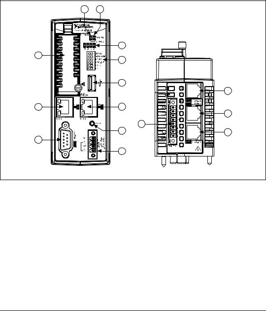
1 |
RS-232 Serial Port |
9 |
RJ-45 Ethernet Port 2 (cFP-2220 Only) |
|
2 |
RJ-45 Ethernet Port 1 |
10 |
Reset Button |
|
3 |
Removable Compact Flash (cFP-2220 Only) |
11 |
Power Connector |
|
4 |
Status LED |
12 |
Digital Input/Output Terminals (cFP-2220 Only) |
|
5 |
Power LED |
13 |
RS-485 |
Serial Port (cFP-2220 Only) |
6 |
User-Configurable LEDs |
14 |
RS-232 |
Serial Port (cFP-2220 Only) |
7 |
DIP Switches |
15 |
RS-232 |
Serial Port (cFP-2210 and cFP-2220 Only) |
8 |
USB Port (cFP-2220 Only) |
|
|
|
|
|
|
|
|
Figure 1. cFP-22xx, Front and Bottom Views
This document describes how to mount the cFP-2200/2210/2220 controllers, how to connect the controllers to networks, and how to use the features of the controllers. This document also contains specifications for the controllers. In this document, the cFP-2200/2210/2220 controllers are referred to inclusively as the cFP-22xx.
What You Need to Install the cFP-22xx
cFP-22xx intelligent real-time controller
cFP-BP-4 or cFP-BP-8 Compact FieldPoint backplane
Compact FieldPoint I/O modules
cFP-2200/2210/2220 |
2 |
ni.com |

Compact FieldPoint connector blocks and/or cables
Ethernet cable
Mounting hardware (DIN rail, panel-mount, or rack-mount accessory)
Two M4 or number 10 panhead screws (for panel mounting only)
Number 2 Phillips screwdriver
14 AWG (1.6 mm) wire with ring lug to fit #8 screw
11–30 VDC Power supply
PC running Windows
FieldPoint software 6.0.1 or later
LabVIEW Real-Time Module 8.5.1 or later
Safety Guidelines
Operate the cFP-22xx only as described in these operating instructions.
Safety Guidelines for Hazardous Locations
The cFP-22xx is suitable for use in Class I, Division 2, Groups A, B, C, D, T4 hazardous locations; Class 1, Zone 2, AEx nL IIC T4 and Ex nL IIC T4 hazardous locations; and nonhazardous locations only. Follow these guidelines if you are installing the cFP-22xx in a potentially explosive environment. Not following these guidelines may result in serious injury or death.
Caution Do not disconnect the power supply wires and connectors from the controller unless power has been switched off.
Caution You must connect the protective earth (PE) ground terminal on the cFP-BP-x backplane to the system safety ground. The backplane PE ground terminal has the following symbol stamped beside it:  . Connect the backplane PE ground terminal to safety ground using 14 AWG (1.6 mm) wire with a ring lug. Use the 5/16 in. panhead screw shipped with the backplane to secure the ring lug to the backplane PE ground terminal.
Caution Substitution of components may impair suitability for Class I, Division 2.
Caution For Zone 2 applications, install the Compact FieldPoint system in an enclosure rated to at least IP 54 as defined by IEC 60529 and EN 60529.
© National Instruments Corporation |
3 |
cFP-2200/2210/2220 |

Caution For Zone 2 applications, install a protection device across the external power supply and the COM terminal. The device must prevent the external power supply voltage from exceeding 42 V if there is a transient overvoltage condition.
Caution The USB port on the cFP-2220 has been tested with the following USB flash drives: SanDisk™ Cruzer® Micro, PNY™ Optima Pro Attaché®, and Swissbit® Swissmemory ™ USB Minitwist. Use only these USB flash drives with the cFP-2220.
Special Conditions for Hazardous Locations Use in Europe
The cFP-22xx has been evaluated as Ex nL IIC T4 equipment under DEMKO Certificate No. 08 ATEX 0724339X. Each controller is marked  II 3G and is suitable for use in Zone 2 hazardous locations. If you are using the cFP-22xx in Gas Group IIC hazardous locations, you must ensure that the ambient temperature is within the range –40 ≤ Ta ≤ 70 °C, and you must use the controller in an NI backplane that has been evaluated as EEx nC IIC T4, Ex nA IIC T4, or Ex nL IIC T4 equipment.
Mounting the Compact FieldPoint Backplane
You can mount the cFP-BP-x backplane on a 35 mm DIN rail, on a panel, or in a standard 19 in. rack. NI recommends DIN rail mounting for the cFP-BP-4 only. Use panel mounting or rack mounting for the cFP-BP-8. Use the panel mounting method for high shock and vibration applications. Before using any mounting method, record the serial number from the back of the backplane. You will be unable to read the serial number after you have mounted the backplane.
cFP-2200/2210/2220 |
4 |
ni.com |
Compact FieldPoint
cFP-2220
POWER
STATUS
A B C D
MANUAL |
IP RESET |
SAFE MODE |
|
|
NO APP |
USER |
CONS OUT |
USER2 |
|
SEE |
USER1 |
|
|
CAUTION – |
|
LINK/ |
|
ACTIVITY |
|
1 |
2 |
10/100 10/100
RESET
-232 |
|
|
|
S |
V1 |
INPUT V03-11 |
MAXA1.5 |
1/R |
|||
|
C |
|
|
|
V2 |
|
|
|
C |
|
|
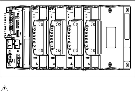
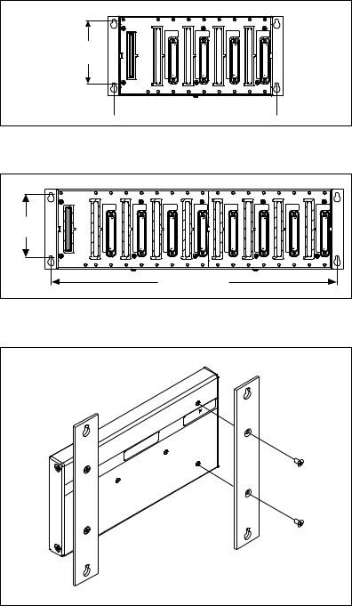
To ensure maximum cooling efficiency, mount the Compact FieldPoint system so that the I/O module vents are at the top and bottom, as shown in the following figure:
POWER |
POWER |
POWER |
POWER |
READY |
READY |
READY |
READY |
28 29 30 31 |
28 29 30 31 |
28 29 30 31 |
28 29 30 31 |
cFP-DI-304 |
cFP-DI-304 |
cFP-DI-304 |
cFP-DI-304 |
Figure 2. cFP-22xx Installed on cFP-BP-4 Mounted Upright
Caution Your installation must meet the following requirements for space and cabling clearance:
•Allow at least 51 mm (2 in.) all around the backplane for air circulation.
•Allow 38 mm (1.5 in.) below and 51 mm (2 in.) above the controller.
© National Instruments Corporation |
5 |
cFP-2200/2210/2220 |

182 mm (7.18 in.) |
|
|
|
|
|
||
in.) |
|||
Min. |
(4.18 |
||
|
|
106 mm |
|
|
|
|
|
Cabling
 Clearance
C
O2
C
O1
C 12 C 11
DI / DO
 4 / RS-485
  3 / RS-232
 2 / RS-232
4 slots = 246 mm (9.68 in.) 8 slots = 441 mm (17.4 in.)
Cooling Outline 51 mm (2 in.) |
Cooling Outline 51 mm (2 in.) |
Figure 3. cFP-22xx Installed on cFP-BP-x, Bottom View with Dimensions
|
|
|
|
|
|
|
4 slots = 246 mm (9.68 in.) |
|
|
|
|
|
|
|
8 slots = 441 mm (17.4 in.) |
|
|
|
Compact FieldPoint |
|
|
|
|
|
|
|
cFP-2220 |
|
|
|
|
|
|
|
|
POWER |
|
POWER |
|
|
|
|
|
STATUS |
|
|
|
|
|
|
|
|
|
READY |
|
|
|
|
A B C D |
|
|
|
|
|
|
|
MANUAL |
IP RESET |
0 |
1 |
2 3 |
|
|
|
SAFE MODE |
|
|
|
|
|
|
|
NO APP |
|
|
|
|
|
|
|
USER |
CONS OUT |
|
|
|
|
|
|
USER2 |
4 |
5 |
6 7 |
|
|
|
|
SEE |
||||
|
|
|
USER1 |
|
|
|
|
|
|
|
CAUTION – |
|
8 |
9 10 11 |
|
|
|
|
|
|
12 13 14 15 |
||
|
|
|
LINK/ |
|
|
|
|
|
|
|
ACTIVITY |
|
|
|
|
|
|
|
|
|
16 17 18 19 |
||
|
|
|
|
|
20 21 22 23 |
||
|
|
10/100 |
10/100 |
|
|
|
|
Min.165mm (6.50in.) |
127mm |
(5.00in.) |
|
RESET |
24 25 26 27 |
||
V1 |
INPUT 11-30 V 1.5 A MAX |
28 29 30 31 |
|||||
|
|
|
|||||
C |
|
|
|
||||
V2 |
|
|
|
||||
C |
|
|
|
||||
|
|
|
|
|
cFP-DI-304 |
||
Cabling Clearance |
|
|
|
|
Cooling Outline 51 mm (2 in.) All Around |
||
Figure 4. cFP-22xx Installed on cFP-BP-4, Front View with Dimensions
cFP-2200/2210/2220 |
6 |
ni.com |
|
104.78 mm |
|
|
|
|
|
|
|
|
|
|
(4.1 in.) |
|
|
|
|
|
|
|
|
|
127.00 mm |
63.50 mm |
|
|
|
|
|
|
|
|
|
(5.0 in.) |
(2.5 in.) |
|
|
|
|
|
|
|
|
|
|
|
|
|
|
|
|
|
|
|
|
|
22.23 mm |
|
|
|
|
|
|
|
|
|
|
(0.9 in.) |
|
|
|
|
|
|
|
|
|
|
33.15 mm |
(1.3 in.) |
129.54 mm |
(5.1 in.) |
311.40 mm |
(12.3 in.) |
387.60 mm |
(15.3 in.) |
407.80 mm |
(16.1 in.) |
|
|
|
|
|
440.94 mm |
|
|
|
|
|
|
|
|
|
|
(17.4 in.) |
|
|
|
|
|
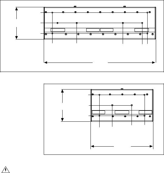
Figure 5. cFP-BP-8, Back View with Dimensions
|
104.74 mm |
|
|
|
|
|
|
|
|
(4.1 in.) |
|
|
|
|
|
|
|
127.00 mm |
63.46 mm |
|
|
|
|
|
|
|
(5.0 in.) |
(2.5 in.) |
|
|
|
|
|
|
|
|
22.19 mm |
|
|
|
|
|
|
|
|
(0.9 in.) |
|
|
|
|
|
|
|
|
34.04 mm |
(1.3 in.) |
84.84 mm |
(3.3 in.) |
161.04 mm |
(6.3 in.) |
211.84 mm |
(8.3 in.) |
|
|
|
|
245.87 mm |
|
|
|
|
|
|
|
|
|
(9.6 in.) |
|
|
|
Figure 6. cFP-BP-4, Back View with Dimensions
Caution Make sure that no I/O modules are in the backplane before mounting it.
© National Instruments Corporation |
7 |
cFP-2200/2210/2220 |
Mounting the Backplane on a DIN Rail
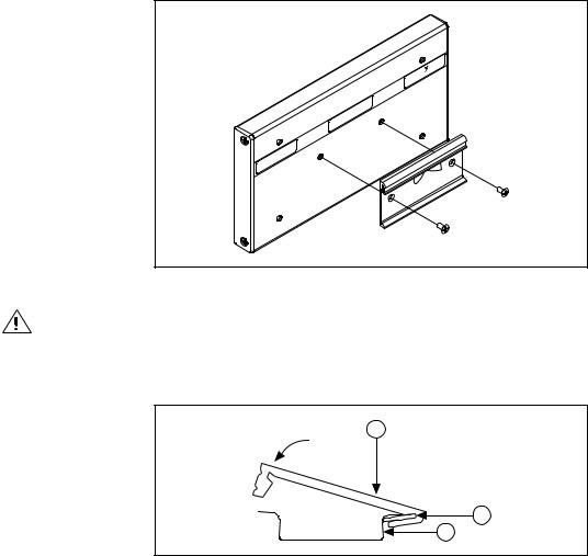
The DIN rail mounting kit is NI part number 778614-01. You need one kit to mount the cFP-BP-4 on a standard 35 mm DIN rail. Complete the following steps to mount the backplane on a DIN rail.
1.Fasten the DIN rail clip to the cFP-BP-4 using a number 2 Phillips screwdriver and the 8-32 × 5/16 in. countersink screws shipped with the mounting kit.
|
L |
|
NA NTS |
NA |
TIOME |
RU |
|
INST |
|
Figure 7. Installing the DIN Rail Clip on the cFP-BP-4
Caution Do not use screws longer than 5/16 in. to fasten the DIN rail clip to the backplane.
2.Insert one edge of the DIN rail into the deeper opening of the DIN rail clip, as shown in Figure 8.
1
2
3
1 DIN Rail Clip |
2 DIN Rail Spring |
3 DIN Rail |
|
|
|
Figure 8. One Edge of DIN Rail Inserted in Clip
cFP-2200/2210/2220 |
8 |
ni.com |
3.Press down firmly on the backplane to compress the spring until the clip locks in place on the DIN rail.
4.Connect the PE ground terminal on the backplane to safety ground.
Caution Disconnect power and make sure that no I/O modules are in the backplane before removing it from the DIN rail.
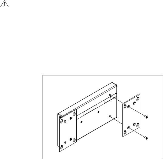
Mounting the Backplane on a Panel
The horizontal panel-mount kit has mounting holes on the sides of the backplane and is NI part number 778616-01. The vertical panel-mount kit has mounting holes on the top and bottom of the backplane and is NI part number 778688-01. Complete the following steps to mount the system on a flat surface.
1.Fasten the panel-mount plates to the back of the cFP-BP-x using a number 2 Phillips screwdriver and the 8-32 × 5/16 in. countersink screws shipped with the kit. You must use these screws because they are the correct depth and thread for the plates and backplane.
NATIONAL |
TS |
INSTRUMEN |
|
Figure 9. Installing the Horizontal Panel-Mount Kit on the cFP-BP-4
© National Instruments Corporation |
9 |
cFP-2200/2210/2220 |
102 mm (4 in.)
 260 mm (10.25 in.)
Figure 10. cFP-BP-4 with Horizontal Panel Mount Kit Installed, Front View with Dimensions
102 mm |
(4 in.) |
457 mm (18 in.) |
Figure 11. cFP-BP-8 with Horizontal Panel-Mount Kit Installed, Front View with Dimensions
|
N |
AL |
S |
|
|
|
NT |
|
|
NA |
TIOME |
|
|
|
RU |
|
|
|
|
INST |
|
|
|
|
Figure 12. Installing the Vertical Panel-Mount Kit on the cFP-BP-4
cFP-2200/2210/2220 |
10 |
ni.com |
34.0 mm (1.34 in.)
7.6 mm (0.30 in.) |
178 mm (7.0 in.) |
178 mm (7 in.) |
152 mm (6 in.) |
17.8 mm (0.70 in.) |
246 mm (9.7 in.) |
Figure 13. cFP-BP-4 with Vertical Panel-Mount Kit Installed,
Front View with Dimensions
33.1 mm (1.31 in.) |
|
7.6 mm |
374 mm (14.7 in.) |
(0.30 in.) |
|
178 mm (7 in.) |
152 mm (6 in.) |
17.8 mm |
457 mm (18 in.) |
(0.70 in.) |
|
Figure 14. cFP-BP-8 with Vertical Panel-Mount Kit Installed,
Front View with Dimensions
2.Bolt or screw the plates to a panel.
3.Connect the PE ground terminal on the cFP-BP-x to safety ground.
Caution Disconnect power and make sure that no I/O modules are in the backplane before removing it from the panel.
© National Instruments Corporation |
11 |
cFP-2200/2210/2220 |
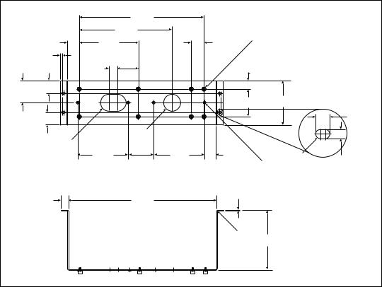
Mounting the Backplane in a Standard 19 in. Rack
The rack-mount kit for Compact FieldPoint is NI part number 778615-01.
The following figure shows the dimensions of the rack-mount kit.
|
|
|
374.65 mm |
|
|
|
|
|
|
|
|
(14.750 in.) |
|
|
|
|
|
|
|
|
278.89 mm |
|
|
|
|
|
|
2× |
|
(10.980 in.) |
|
|
8× Diameter |
|
|
|
177.8 mm |
|
38.1 mm |
|
||||
|
34.93 mm |
|
|
+0.07 mm |
|
|||
|
(1.375 in.) |
(7.000 in.) |
|
(1.500 in.) |
7.92 mm |
|
||
|
2× |
|
|
|
|
|
0 mm |
|
|
|
|
|
|
(0.312 in. |
+0.003 in. |
|
|
|
6.91 mm |
|
|
|
|
–0.000 in. ) |
|
|
|
(0.272 in.) |
25.4 mm |
|
|
|
|
|
|
|
|
|
|
|
|
|
|
|
|
|
(1.000 in.) |
63.07 mm |
|
|
25.02 mm |
(0.985 in.) |
|
|
|
|
|
|
|
|||
|
|
|
(2.483 in.) |
|
|
|
|
|
66.29 mm |
37.69 mm |
|
|
|
|
|
|
|
(1.484 in.) |
|
|
|
|
|
|
|
|
(2.610 in.) |
|
|
|
|
|
|
|
|
|
|
|
|
|
82.52 mm |
132.56 mm |
|
|
|
|
|
|
|
(5.219 in.) |
|
||
|
|
|
|
|
(3.249 in.) |
4× |
||
|
|
|
|
|
|
|||
|
37.72 mm |
|
|
|
|
|
|
10.59 mm |
|
(1.485 in.) |
|
|
|
|
|
|
(0.417 in.) |
|
|
|
Diameter |
|
|
|
|
|
|
|
|
50.8 mm |
|
|
|
|
|
|
2× Radius |
|
(2.00 in.) |
|
|
|
|
|
|
25.4 mm |
|
|
|
|
|
|
|
|
(1.000 in.) |
152.15 mm |
|
152.4 mm |
33.15 mm |
|
Full Radius |
|
|
|
(5.990 in.) |
76.2 mm |
(6.000 in.) |
(1.305 in.) |
|
7.06 mm |
|
|
|
|
|
|||||
|
|
|
(3.000 in.) |
|
|
Diameter |
+0.07 mm |
(0.278 in.) |
|
|
|
|
|
|
6.35 mm |
|
|
|
|
|
|
|
|
–0.02 mm |
|
|
|
|
|
|
|
|
(0.250 in. |
+0.003 in. |
|
|
|
|
|
|
|
–0.001 in. ) |
|
|
|
2× |
|
|
|
2.29 mm |
|
|
|
|
|
444.5 mm |
|
(0.090 in.) |
|
|
|
|
|
21.34 mm |
|
|
|
|
|
|
|
|
|
(17.500 in.) |
|
|
|
|
|
|
|
(0.840 in.) |
|
|
|
|
|
|
|
|
|
|
|
|
|
|
|
|
|
|
|
|
|
4× Radius |
179.32 mm |
|
|
|
|
|
|
|
2.29 mm |
|
||
|
|
|
|
|
(7.060 in.) |
|
||
|
|
|
|
|
(0.090 in.) |
|
||
|
|
|
|
|
|
|
|
|
Figure 15. Dimensions of Rack-Mount Kit
Complete the following steps to mount the system in a rack.
1.Fasten the rack-mount bracket to the back of the cFP-BP-x using the captive screws on the bracket.
cFP-2200/2210/2220 |
12 |
ni.com |
Loading...