

Page 1
GETTING STARTED GUIDE
2
3
1
cRIO-9803
SSD Expansion Module for CompactRIO
This document provides information to help you get started with the cRIO-9803, including
installing the SSD, connecting the module to a controller, and formatting the drive.
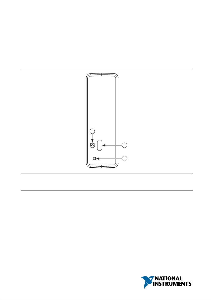
Figure 1. cRIO-9803 Front Panel
1. USB retention screw
2. USB Type-C upstream-facing (device) port
3. Power/Status LED
Page 2

Table 1. LED Indications
LED Color Behavior Indication
Solid Drive is powered on and idle.
Flashing, 10 Hz Drive is connected at USB High Speed and active.
Power/Status
Blue
Flashing, 20 Hz Drive is connected at USB SuperSpeed and active.
Fading Drive is suspended by operating system.
— Off Device is powered off.
Unpacking the Kit
Notice To prevent electrostatic discharge (ESD) from damaging the device, ground
yourself using a grounding strap or by holding a grounded object, such as your
computer chassis.
1. Touch the antistatic package to a metal part of the computer chassis.
2. Remove the device from the package and inspect the device for loose components or any
other sign of damage.
Notice Never touch the exposed pins of connectors.
Note Do not install a device if it appears damaged in any way.
3. Unpack any other items and documentation from the kit.
Store the device in the antistatic package when the device is not in use.
What You Need to Get Started
Kit Contents
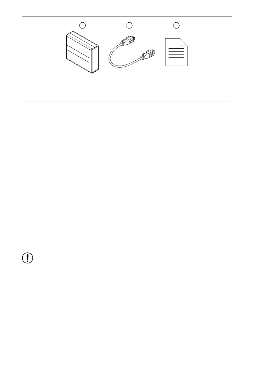
Verify that the following items are included in the cRIO-9803 kit.
2 | ni.com | cRIO-9803 Getting Started Guide
Page 3
1
3
2
1. cRIO-9803
2. Type-C to Type-C USB cable
3. Safety, Environmental, and Regulatory Information document
Required Components
• CompactRIO Controller or host computer
Recommended Components
• Type-C to Type-A USB cable, user-provided
Installing the SSD on the cRIO-9803
If the cRIO-9803 does not come with the solid-state drive (SSD) installed, refer to the
following steps for installation procedures.
What to Use
• cRIO-9803 empty drive, 785921-01
• Thermal pad, included with the 785921-01
• Screwdriver, Torx T10
• Screwdriver, Phillips #1
• mSATA full-size SSD, user-provided
What to Do
Notice The performance of this product can be disrupted if subjected to
Electrostatic Discharge (ESD) during operation. To prevent damage, industrystandard ESD prevention measures must be employed during installation,
maintenance, and operation.
1. Use the Torx screwdriver to remove the four side screws from the module.
2. Remove the module cover and locate the drive socket.
3. Remove the liner from the thermal pad and affix it to the bottom of the drive with the
pink side facing away from the drive.
cRIO-9803 Getting Started Guide | © National Instruments | 3
Page 4

Figure 2. Affixing the Thermal Pad
4. Use the Phillips screwdriver to remove the two SSD mounting screws.
5. Insert the drive into the drive socket.
Figure 3. Inserting the SSD into the Drive Socket
6. Secure the drive using the two SSD mounting screws, gently compressing the thermal
pad.
4 | ni.com | cRIO-9803 Getting Started Guide
Page 5

Figure 4. Securing the Drive
7. Replace the module cover and secure it using the four side screws.
Mounting the cRIO-9803
You can mount the cRIO-9803 with a CompactRIO chassis. For instructions and guidelines
about the various chassis mounting configurations, refer to the Expansion Module for
CompactRIO User Manual on ni.com/manuals.
You can also use the cRIO-9803 with a variety of hardware systems and configurations. For
more information about using the module with non-CompactRIO systems, contact NI.
Grounding the cRIO-9803
For information about grounding the cRIO-9803, refer to the Expansion Module for
CompactRIO User Manual on ni.com/manuals.
Connecting the cRIO-9803 to a CompactRIO Controller
Complete the following steps to connect the cRIO-9803 to a cRIO Controller using the USB
upstream-facing port
What to Use
• cRIO-9803
• CompactRIO controller
• One of the following USB cables:
– Type-C to Type-C USB cable, provided in the shipping kit
– Type-C to Type-A USB cable, user-provided
cRIO-9803 Getting Started Guide | © National Instruments | 5
Page 6

What to do
cRIO-904
cRIO-9803
Figure 5. Connecting the Module to a Controller
1. Power off the CompactRIO controller.
2. Connect one end of the USB cable to any available USB Type-C host port on the
CompactRIO controller.
3. Secure the USB connector to the CompactRIO controller using the retention screw.
4. Connect the other end of USB cable to the USB Type-C upstream-facing port on the
module.
5. Secure the USB connector to the module using the retention screw.
6. Power on the CompactRIO controller.
7. Verify the Power/Status LED is on, solid or flashing, indicating drive activity.
Formatting the cRIO-9803
You must format the drive with the appropriate file system based on system and application
requirements.
Note For more information about using mass storage devices with LabVIEW Real-
Time targets, go to ni.com/info and enter Info Code rtstorage.
6 | ni.com | cRIO-9803 Getting Started Guide
Page 7

Table 2. File System Formatting
Native
File System Type
ext4 Journaling Linux
fat32 Non-journaling Windows
Operating
System Notes
Drives formatted as ext4 may require a file
system driver to access from a Windows
system.
Drives formatted as fat32 can be accessed
from both Linux and Windows systems.
Maximum available storage may be
limited to 32 GB.
NTFS — Windows
exFAT — Windows
Note National Instruments recommends ext4 for applications that require the
maximum reliability and for drives larger than 32 GB.
Note Linux commands fdisk and mkfs may be used to partition and format the
drive. For more information about selecting and setting up file systems in LabVIEW
Real-Time, go to ni.com/info and enter Info Code rtfilesys.
NTFS file systems are not supported by
CompactRIO.
exFAT file systems are not supported by
CompactRIO.
Accessing the cRIO-9803
The CompactRIO system automatically mounts the formatted cRIO-9803 starting with drive
U. You can access this drive using file path /u/.../.
If more than one drive is present, including multiple cRIO-9803 modules or an SD card, the
CompactRIO system mounts additional drives alphabetically as V, W, and so on.
Note Drive order may change based on the presence and connection order of
external mass storage drives.
Worldwide Support and Services
The NI website is your complete resource for technical support. At ni.com/support, you have
access to everything from troubleshooting and application development self-help resources to
email and phone assistance from NI Application Engineers.
Visit ni.com/services for information about the services NI offers.
Visit ni.com/register to register your NI product. Product registration facilitates technical
support and ensures that you receive important information updates from NI.
cRIO-9803 Getting Started Guide | © National Instruments | 7
Page 8

NI corporate headquarters is located at 11500 North Mopac Expressway, Austin, Texas,
78759-3504. NI also has offices located around the world. For support in the United States,
create your service request at ni.com/support or dial 1 866 ASK MYNI (275 6964). For
support outside the United States, visit the Worldwide Offices section of ni.com/niglobal to
access the branch office websites, which provide up-to-date contact information.
Information is subject to change without notice. Refer to the NI Trademarks and Logo Guidelines at ni.com/trademarks for
information on NI trademarks. Other product and company names mentioned herein are trademarks or trade names of their
respective companies. For patents covering NI products/technology, refer to the appropriate location: Help»Patents in your
software, the patents.txt file on your media, or the National Instruments Patent Notice at ni.com/patents. You can find
information about end-user license agreements (EULAs) and third-party legal notices in the readme file for your NI product. Refer
to the Export Compliance Information at ni.com/legal/export-compliance for the NI global trade compliance policy and how
to obtain relevant HTS codes, ECCNs, and other import/export data. NI MAKES NO EXPRESS OR IMPLIED WARRANTIES AS
TO THE ACCURACY OF THE INFORMATION CONTAINED HEREIN AND SHALL NOT BE LIABLE FOR ANY ERRORS. U.S.
Government Customers: The data contained in this manual was developed at private expense and is subject to the applicable
limited rights and restricted data rights as set forth in FAR 52.227-14, DFAR 252.227-7014, and DFAR 252.227-7015.
© 2018—2019 National Instruments. All rights reserved.
377727B-01 August 2, 2019
 Loading...