

Page 1
USER MANUAL AND SPECIFICATIONS
NI cRIO-907x
1
3
5
2
4
6
7
8
POWER
FPGA
STATUS
USER1
DO NOT SEPARATE CABLES WHEN
ENERGIZED IN HAZARDOUS LOCATIONS
SAFE MODE
CONSOLE OUT
IP RESET
NO APP
USER1
NO FPGA
LINK
LINK
10/
100
10/
100
RESET
INPUT
19-30 V
20 W MAX
TRIGGER
V
C
NC
C
NI cRIO-9072/9073/9074
Reconfigurable Embedded Chassis with Integrated Intelligent RealTime Controller for CompactRIO
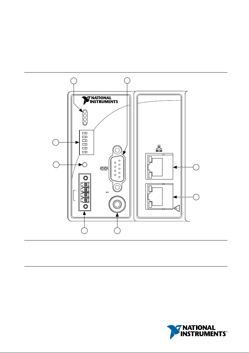
Figure 1. CompactRIO cRIO-9072/9073/9074
1. LEDs
2. RS-232 Serial Port
3. RJ-45 Ethernet Port 2 (cRIO-9074 Only)
This document describes how to connect the cRIO-9072/9073/9074 to a network and how to
use the features of the cRIO-9072/9073/9074.
4. RJ-45 Ethernet Port 1
5. SMB Connector (cRIO-9074 Only)
6. Power Connector
7. Reset Button
8. DIP Switches
Page 2
Safety Guidelines
Operate the cRIO-9072/9073/9074 only as described in this document.
Caution Do not operate the cRIO-9072/9073/9074 in a manner not specified in
this document. Product misuse can result in a hazard. You can compromise the
safety protection built into the product if the product is damaged in any way. If the
product is damaged, return it to NI for repair.
Safety Guidelines for Hazardous Locations
The cRIO-9072/9073/9074 is suitable for use in Class I, Division 2, Groups A, B, C, D, T4
hazardous locations; Class I, Zone 2, AEx nA IIC T4 and Ex nA IIC T4 hazardous locations;
and nonhazardous locations only. Follow these guidelines if you are installing the
cRIO-9072/9073/9074 in a potentially explosive environment. Not following these guidelines
may result in serious injury or death.
Caution Do not disconnect the power supply wires and connectors from the
controller unless power has been switched off.
Caution Do not disconnect I/O-side wires or connectors unless power has been
switched off or the area is known to be nonhazardous.
Caution Do not remove modules unless power has been switched off or the area is
known to be nonhazardous.
Caution Substitution of components may impair suitability for Class I, Division 2.
Caution For Division 2 and Zone 2 applications, install the system in an enclosure
rated to at least IP54 as defined by IEC/EN 60079-15.
Special Conditions for Hazardous Locations Use in Europe and Internationally
The cRIO-9072/9073/9074 has been evaluated as Ex nA IIC T4 Gc equipment under DEMKO
Certificate No. 07 ATEX 0626664X and is IECEx UL 14.0089X certified. Each device is
marked
of -20 °C ≤ Ta ≤ 55 °C.
2 | ni.com | NI cRIO-9072/9073/9074 User Manual and Specifications
II 3G and is suitable for use in Zone 2 hazardous locations, in ambient temperatures
Caution You must make sure that transient disturbances do not exceed 140% of
the rated voltage.
Caution The system shall only be used in an area of not more than Pollution
Degree 2, as defined in IEC 60664-1.
Caution The system shall be mounted in an ATEX/IECEx-certified enclosure with
a minimum ingress protection rating of at least IP54 as defined in IEC/EN 60079-15.
Page 3

Caution The enclosure must have a door or cover accessible only by the use of a
tool.
Electromagnetic Compatibility Guidelines
This product was tested and complies with the regulatory requirements and limits for
electromagnetic compatibility (EMC) stated in the product specifications. These requirements
and limits provide reasonable protection against harmful interference when the product is
operated in the intended operational electromagnetic environment.
This product is intended for use in industrial locations. However, harmful interference may
occur in some installations, when the product is connected to a peripheral device or test object,
or if the product is used in residential or commercial areas. To minimize interference with
radio and television reception and prevent unacceptable performance degradation, install and
use this product in strict accordance with the instructions in the product documentation.
Furthermore, any changes or modifications to the product not expressly approved by National
Instruments could void your authority to operate it under your local regulatory rules.
Special Conditions for Marine Applications
Some products are Lloyd’s Register (LR) Type Approved for marine (shipboard) applications.
To verify Lloyd’s Register certification for a product, visit ni.com/certification and search for
the LR certificate, or look for the Lloyd’s Register mark on the product.
Caution In order to meet the EMC requirements for marine applications, install the
product in a shielded enclosure with shielded and/or filtered power and input/output
ports. In addition, take precautions when designing, selecting, and installing
measurement probes and cables to ensure that the desired EMC performance is
attained.
What You Need to Install CompactRIO Reconfigurable Embedded Hardware
• CompactRIO reconfigurable embedded chassis with integrated intelligent real-time
controller
• C Series I/O modules
• DIN rail mount kit (for DIN rail mounting only)
• Two M4 or number 10 panhead screws (for panel mounting only)
• A number 2 Phillips screwdriver
• Power supply
Note Visit ni.com/info and enter the Info Code rdsoftwareversion to
determine which software you need to use the cRIO-9072/9073/9074.
NI cRIO-9072/9073/9074 User Manual and Specifications | © National Instruments | 3
Page 4
Note The cRIO-9072/9073/9074 may be shipped with a clear protective film cover
29.0 mm
(1.14 in.)
58.9 mm
(2.32 in.)
3.3 mm
(0.13 in.)
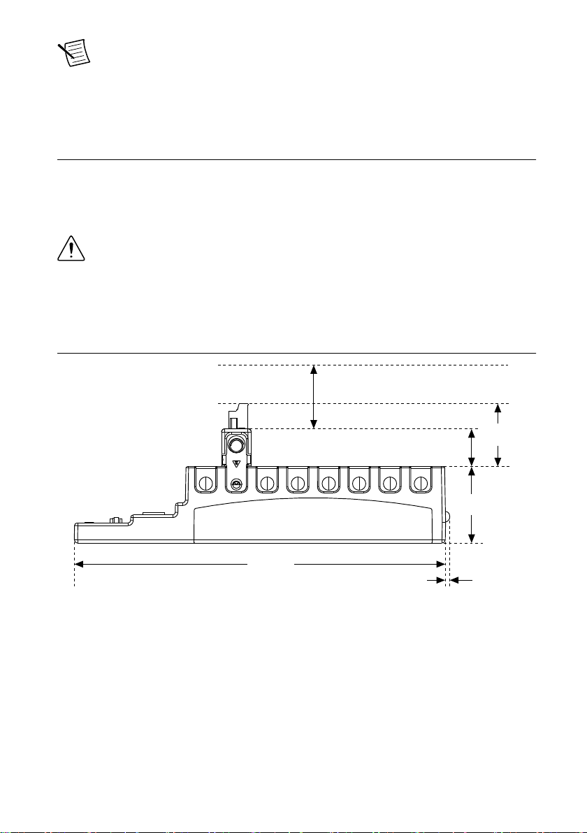
Cabling Clearance
50.8 mm (2.00 in.)
48.4 mm
(1.91 in.)
286.4 mm
(11.28 in.)
on the front panel. You can remove the film cover before installing the
cRIO-9072/9073/9074.
Mounting the CompactRIO Reconfigurable Embedded Chassis
You can mount the chassis in any orientation on a 35 mm DIN rail or on a panel. Use the DIN
rail mounting method if you already have a DIN rail configuration or if you need to be able to
quickly remove the CompactRIO chassis. Use the panel mount method for high shock and
vibration applications.
Caution Your installation must meet the following requirements for space and
cabling clearance:
• Allow 25.4 mm (1 in.) on the top and the bottom of the chassis for air
circulation.
• Allow 50.8 mm (2 in.) in front of modules for cabling clearance for common
connectors, such as the 10-terminal, detachable screw terminal connector.
Figure 2. cRIO-9072/9073/9074 Bottom View with Dimensions
4 | ni.com | NI cRIO-9072/9073/9074 User Manual and Specifications
Page 5

Figure 3. cRIO-9072/9073/9074 Front View with Dimensions
165.1 mm
(6.50 in.)
3.1 mm
(0.12 in.)
51.1 mm
(2.04 in.)
36.4 mm
(1.43 in.)
19.0 mm
(0.75 in.)
NI cRIO-907x
88.1 mm
(3.47 in.)
1
3X M4X0.7
25 mm
(0.98 in.)
44 mm
(1.73 in.)
23.7 mm
(0.94 in.)
63.1 mm
(2.48 in.)
44.1 mm
(1.74 in.)
1. Chassis grounding terminal
Figure 4. cRIO-9072/9073/9074 Side View with Dimensions
The following sections contain instructions for the mounting methods. Before using any of
these mounting methods, record the serial number from the back of the chassis. You will be
unable to read the serial number after you have mounted the chassis.
Caution Make sure that no I/O modules are in the chassis before mounting it.
NI cRIO-9072/9073/9074 User Manual and Specifications | © National Instruments | 5
Page 6
Mounting the Chassis on a Panel
NI cRIO-9074
31.8 mm
(1.25 in.)
NI cRIO-9074
15.5 mm
(0.61 in.)
9.5 mm
(0.38 in.)
28.1 mm
(1.11 in.)
63.5 mm
(2.50 in.)
88.1 mm
(3.47 in.)
311.2 mm
(12.25 in.)
330.2 mm
(13.00 in.)
Panel or wall mounting is the best method for applications that are subject to high shock and
vibration. You can use the NI 9905 panel mount kit to mount the cRIO-9072/9073/9074 on a
flat surface. Complete the following steps.
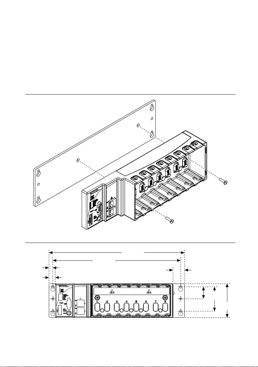
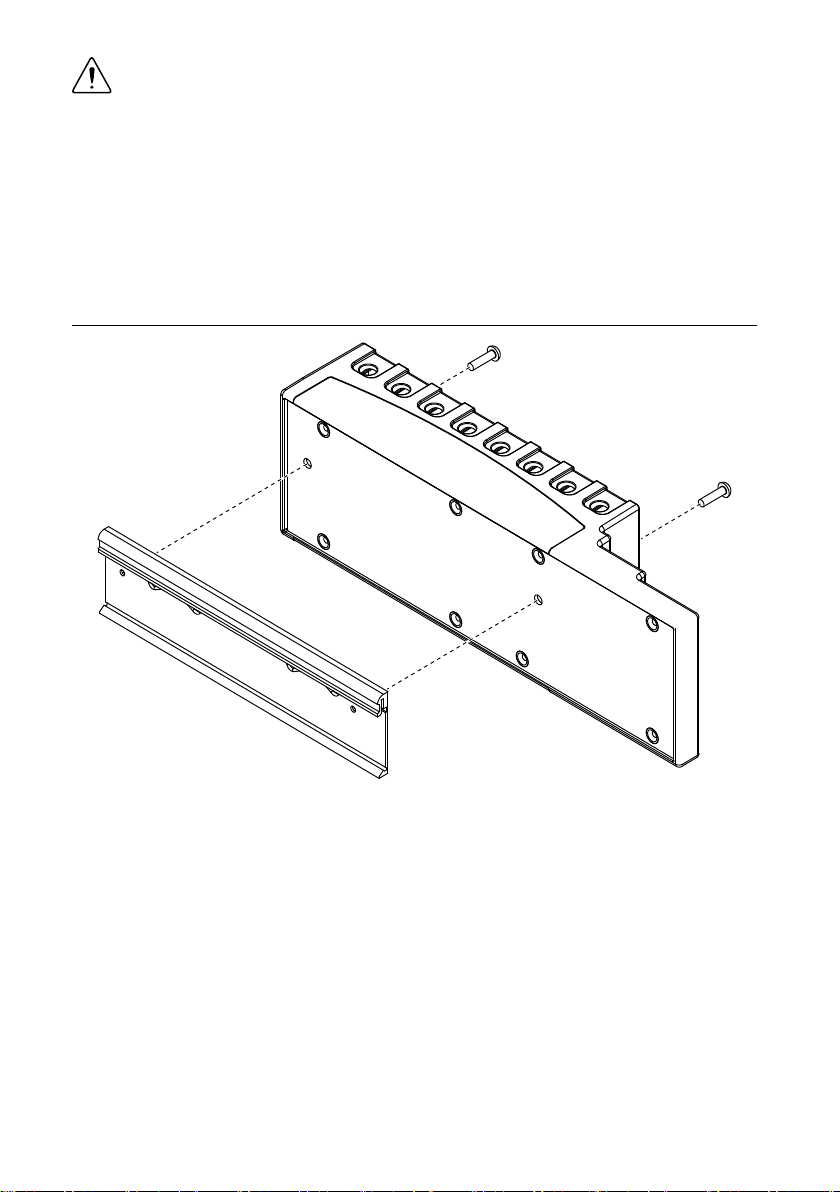
1. Fasten the chassis to the panel mount kit using a number 2 Phillips screwdriver and two
M4 × 16 screws. NI provides these screws with the panel mount kit. You must use these
screws because they are the correct depth and thread for the panel. Tighten the screws to a
maximum torque of 1.3 N · m (11.5 lb · in.).
Figure 5. Installing the Panel Mount Accessory on the cRIO-9072/9073/9074
Figure 6. Dimensions of cRIO-9072/9073/9074 with Panel Mount Accessory Installed
2. Fasten the NI 9905 panel to the wall using the screwdriver and screws that are
appropriate for the wall surface. The maximum screw size is M4 or number 8.
6 | ni.com | NI cRIO-9072/9073/9074 User Manual and Specifications
Page 7
Caution Make sure that no I/O modules are in the chassis before removing it from
the panel.
Mounting the Chassis on a DIN Rail
You can order the NI 9915 DIN rail mount kit if you want to mount the chassis on a DIN rail.
You need one clip for mounting the chassis on a standard 35 mm DIN rail. Complete the
following steps to mount the chassis on a DIN rail.
1. Fasten the DIN rail clip to the chassis using a number 2 Phillips screwdriver and two
M4 × 16 screws. NI provides these screws with the DIN rail mount kit. Tighten the
screws to a maximum torque of 1.3 N · m (11.5 lb · in.).
Figure 7. Installing the DIN Rail Clip on the cRIO-9072/9073/9074
2. Insert one edge of the DIN rail into the deeper opening of the DIN rail clip.
NI cRIO-9072/9073/9074 User Manual and Specifications | © National Instruments | 7
Page 8
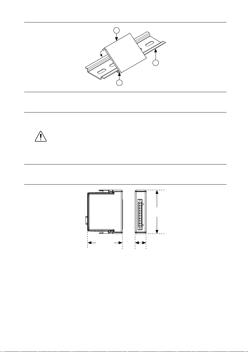
Figure 8. One Edge of the DIN Rail Inserted in a Clip
3
2
1
88.1 mm
(3.47 in.)
70.7 mm
(2.78 in.)
22.9 mm
(0.90 in.)
1. DIN Rail Clip
2. DIN Rail
3. DIN Rail Spring
3. Press down firmly on the chassis to compress the spring until the clip locks in place on
the DIN rail.
Caution Make sure that no I/O modules are in the chassis before removing it
from the DIN rail.
Installing C Series I/O Modules in the Chassis
The following figure shows the mechanical dimensions of C Series I/O modules.
Figure 9. C Series I/O Module, Front and Side View with Dimensions
Complete the following steps to install a C Series I/O module in the chassis.
1. Make sure that no I/O-side power is connected to the I/O module. If the system is in a
nonhazardous location, the chassis power can be on when you install I/O modules.
2. Align the I/O module with an I/O module slot in the chassis. The module slots are labeled
1 to 8, left to right.
8 | ni.com | NI cRIO-9072/9073/9074 User Manual and Specifications
Page 9

Figure 10. Installing an I/O Module in the Chassis
NI cRIO-9074
1
2
1. Insertion Groove
2. Latch
3. Squeeze the latches and insert the I/O module into the module slot.
4. Press firmly on the connector side of the I/O module until the latches lock the I/O module
into place.
5. Repeat these steps to install additional I/O modules.
Removing I/O Modules from the Chassis
Complete the following steps to remove a C Series I/O module from the chassis.
1. Make sure that no I/O-side power is connected to the I/O module. If the system is in a
nonhazardous location, the chassis power can be on when you remove I/O modules.
2. Squeeze the latches on both sides of the module and pull the module out of the chassis.
Connecting the Chassis to a Network
Connect the chassis to an Ethernet network using the RJ-45 Ethernet port on the controller
front panel. Use a standard Category 5 (CAT-5) or better shielded, twisted-pair Ethernet cable
to connect the chassis to an Ethernet hub, or use an Ethernet crossover cable to connect the
chassis directly to a computer.
NI cRIO-9072/9073/9074 User Manual and Specifications | © National Instruments | 9
Page 10

Caution To prevent data loss and to maintain the integrity of your Ethernet
installation, do not use a cable longer than 100 m.
If you need to build your own cable, refer to the Cabling section for more information about
Ethernet cable wiring connections.
The first time you power up the chassis, the BIOS network settings determine the initial IP
settings and other network behavior. After powerup, you must install software on the chassis
and configure the network settings in NI Measurement & Automation Explorer (MAX).
Note Installing software may change the network behavior of the chassis. For
information about network behavior by installed software version, go to ni.com/info
and enter the Info Code ipconfigcrio.
The BIOS network settings of the cRIO-9072/9073/9074 depend on the part number of the
chassis. The part number is located on the bottom of the chassis.
BIOS Network Settings of cRIO-9072/9073/9074 with Part Number Beginning 192172
If the part number of the cRIO-9072/9073/9074 begins with 192172, the IP address, subnet
mask, DNS address, gateway, and Time Server IP are all set to 0.0.0.0 at powerup.
The host computer communicates with the chassis over a standard Ethernet connection. If the
host computer is on a network, you must configure the chassis on the same subnet as the host
computer. If neither the host computer nor the chassis is connected to a network, you can
connect the two directly using a crossover cable.
If you want to use the chassis on a subnet other than the one the host computer is on, first
connect the chassis on the same subnet as the host computer. Use DHCP to assign an IP
address or reassign a static IP address for the subnet where you want it to be and physically
move it to the other subnet.
BIOS Network Settings of cRIO-9072/9073/9074 with Part Number Beginning 198944
If the part number of the cRIO-9072/9073/9074 begins with 198944, the chassis attempts to
initiate a DHCP network connection at powerup. If the chassis is unable to initiate a DHCP
connection, it connects to the network with a link-local IP address with the form
169.254.x.x.
The host computer communicates with the chassis over a standard Ethernet connection. If
neither the host computer nor the chassis is connected to a network, you can connect the two
directly using a crossover cable.
Connecting the Chassis to Earth Ground
You must connect the chassis grounding screw to earth ground. Complete the following steps
to connect to earth ground.
1. Attach a ring lug to a 1.6 mm2 (14 AWG) or larger wire.
10 | ni.com | NI cRIO-9072/9073/9074 User Manual and Specifications
Page 11

2. Remove the grounding screw from the grounding terminal on the right side of the chassis.
C
NC
C
V
2
1
2
3. Attach the ring lug to the grounding terminal.
4. Tighten the grounding screw to 0.5 N · m (4.4 lb · in.) of torque.
5. Attach the other end of the wire to the grounding electrode system of your facility using a
method appropriate for the application.
Caution If you use shielded cabling to connect to a C Series I/O module with
a plastic connector, you must attach the cable shield to the chassis grounding
terminal using 1.3 mm2 (16 AWG) or larger wire. Attach a ring lug to the wire
and attach the wire to the chassis grounding terminal. Solder the other end of
the wire to the cable shield. Use shorter wire for better EMC performance.
For more information about ground connections, go to ni.com/info and enter the Info
Code emcground.
Wiring Power to the Chassis
The cRIO-9072/9073/9074 requires an external power supply that meets the specifications in
the Power Requirements section. The cRIO-9072/9073/9074 filters and regulates the supplied
power and provides power for all of the I/O modules. The cRIO-9072/9073/9074 has one layer
of reverse-voltage protection. Complete the following steps to connect a power supply to the
chassis.
1. Connect the positive lead of the power supply to the V terminal of the power connector
shipped with the cRIO-9072/9073/9074, and tighten the terminal screw. The following
figure shows the terminal screws, which secure the wires in the screw terminals, and the
connector screws, which secure the power connector on the front panel.
Figure 11. Power Connector
1. Terminal Screws
2. Connector Screws
2. Connect the negative lead of the power supply to one of the C terminals of the power
connector and tighten the terminal screw.
3. Optionally, you can connect the positive lead of another power supply to the other V
terminal and the negative lead to one of the C terminals.
4. Install the power connector on the front panel of the cRIO-9072/9073/9074 and tighten
the connector screws.
NI cRIO-9072/9073/9074 User Manual and Specifications | © National Instruments | 11
Page 12

Caution The C terminals are internally connected to each other.
Powering On the cRIO-9072/9073/9074
When you apply power to the cRIO-9072/9073/9074, the controller runs a power-on self test
(POST). During the POST, the Power and Status LEDs turn on. The Status LED turns off,
indicating that the POST is complete. If the LEDs do not behave in this way when the system
powers on, refer to the Understanding LED Indications section.
You can configure the cRIO-9072/9073/9074 to launch an embedded stand-alone LabVIEW
RT application each time you boot the controller. Refer to the LabVIEW Help for more
information.
Chassis Reset Options
The following table lists the reset options available on CompactRIO systems such as the
cRIO-9072/9073/9074. These options determine how the chassis behaves when the controller
is reset in various conditions. Use the RIO Device Setup utility to select reset options. Access
the RIO Device Setup utility by selecting Start»All Programs»National Instruments»NI-
RIO»RIO Device Setup.
Table 1. CompactRIO Reset Options
Chassis Reset Option Behavior
Do not autoload VI Does not load the FPGA bit stream from flash memory.
Autoload VI on device
powerup
Autoload VI on device reboot Loads the FPGA bit stream from flash memory to the FPGA
Loads the FPGA bit stream from flash memory to the FPGA
when the controller powers on.
when you reboot the controller either with or without
cycling power.
Chassis Sleep Mode
The cRIO-9072/9073/9074 supports a low-power sleep mode. Refer to the software
documentation for information about enabling sleep mode.
Connecting Serial Devices to the cRIO-9072/9073/9074
The cRIO-9072/9073/9074 has an RS-232 serial port to which you can connect devices such
as displays or input devices. Use the Serial VIs to read from and write to the serial port from a
LabVIEW RT application. For more information about the Serial VIs, refer to the LabVIEW
Help.
12 | ni.com | NI cRIO-9072/9073/9074 User Manual and Specifications
Page 13

Figure 12. Controller Serial Port
Pin 1
Pin 5
Pin 6
Pin 9
Table 2. DB-9 Pin Descriptions
Pin Signal
1 DCD
2 RXD
3 TXD
4 DTR
5 GND
6 DSR
7 RTS
8 CTS
9 RI
Using the Internal Real-Time Clock
The system clock of the cRIO-9072/9073/9074 is synchronized with the internal highprecision real-time clock at startup. This synchronization provides timestamp data to the
controller. You can also use the internal real-time clock to correct drift of the system clock.
Refer to the Internal Real-Time Clock Specifications for the accuracy specifications of the
real-time clock.
Using the SMB Connector for Digital I/O (cRIO-9074 only)
You can use the SMB connector of the cRIO-9072/9073/9074 to connect digital devices to the
controller. For example, if you connect the pulse-per-second output of a GPS device to the
SMB connector of the cRIO-9072/9073/9074, you can use the GPS device to correct for drift
of the system clock.
For software that supports GPS drift-correction and other digital I/O through the SMB
connector, go to ni.com/info and enter the Info Code criosmb.
NI cRIO-9072/9073/9074 User Manual and Specifications | © National Instruments | 13
Page 14

Configuring DIP Switches
1 65432
SAFE MODE
CONSOLE OUT
IP RESET
NO APP
USER1
NO FPGA
OFF
Figure 13. DIP Switches
All of the DIP switches are in the OFF position when the chassis is shipped from National
Instruments.
SAFE MODE Switch
The position of the SAFE MODE switch determines whether the embedded LabVIEW RealTime engine launches at startup. If the switch is in the OFF position, the LabVIEW Real-Time
engine launches. Keep this switch in the OFF position during normal operation. If the switch is
in the ON position at startup, the cRIO-9072/9073/9074 launches only the essential services
required for updating its configuration and installing software. The LabVIEW Real-Time
engine does not launch.
If the software on the controller is corrupted, you must put the controller into safe mode and
reformat the controller drive. You can put the controller into safe mode by powering it up
either with the SAFE MODE switch in the ON position or with no software installed on the
drive. Refer to the Measurement & Automation Explorer Help for more information about
installing software on a controller and reformatting the drive on the controller.
CONSOLE OUT Switch
With a serial-port terminal program, you can use the CONSOLE OUT switch to read the IP
address and firmware version of the controller. Use a null-modem cable to connect the serial
port on the chassis to a computer. Push the switch to the ON position. Make sure that the
serial-port terminal program is configured to the following settings:
• 9,600 bits per second
• Eight data bits
• No parity
• One stop bit
• No flow control
The serial-port terminal program displays the IP address and firmware version of the chassis.
Keep this switch in the OFF position during normal operation.
14 | ni.com | NI cRIO-9072/9073/9074 User Manual and Specifications
Page 15

IP RESET Switch
Push the IP RESET switch to the ON position and reboot the controller to reset the IP address
and other TCP/IP settings of the controller to the factory defaults. Refer to the Troubleshooting
Network Communication section for more information about resetting the IP address. You also
can push this switch to the ON position to unlock a chassis that was previously locked in
MAX.
NO APP Switch
Push the NO APP switch to the ON position to prevent a LabVIEW RT startup application
from running at startup. If you want to permanently disable a LabVIEW RT application from
running at startup, you must disable it in LabVIEW. To run an application at startup, push the
NO APP switch to the OFF position, create an application using the LabVIEW Application
Builder, and configure the application in LabVIEW to launch at startup. If you already have an
application configured to launch at startup and you push the NO APP switch from ON to OFF,
the startup application is automatically enabled. For more information about automatically
launching VIs at startup and disabling VIs from launching at startup, refer to the LabVIEW
Help.
USER1 Switch
You can define the USER1 switch for your application. To define the purpose of this switch in
your embedded application, use the RT Read Switch VI in your LabVIEW RT embedded VI.
For more information about the RT Read Switch VI, refer to the LabVIEW Help.
NO FPGA Switch
Push the NO FPGA switch to the ON position to prevent a LabVIEW FPGA application from
loading at startup. The NO FPGA switch overrides the CompactRIO reset options described in
the Chassis Reset Options section. After startup you can download to the FPGA from software
regardless of switch position.
Using the RESET Button
Pressing the RESET button resets the processor in the same manner as cycling power.
Note The FPGA continues to run unless you select the Autoload on Any Device
Reset boot option. Refer to the Chassis Reset Options section for more information.
NI cRIO-9072/9073/9074 User Manual and Specifications | © National Instruments | 15
Page 16

Understanding LED Indications
POWER
FPGA
STATUS
USER1
Figure 14. cRIO-9072/9073/9074 LEDs
POWER LED
The POWER LED is lit while the cRIO-9072/9073/9074 is powered on. This LED indicates
that the power supply connected to the chassis is adequate.
FPGA LED
You can use the FPGA LED to help debug your application or easily retrieve application
status. Use the LabVIEW FPGA Module and NI-RIO software to define the FPGA LED to
meet the needs of your application. Refer to LabVIEW Help for information about
programming this LED.
STATUS LED
The STATUS LED is off during normal operation. The cRIO-9072/9073/9074 indicates
specific error conditions by flashing the STATUS LED a certain number of times every few
seconds, as shown in the following table
Number of
Flashes Every
Few Seconds Indication
The chassis is unconfigured. Use MAX to configure the chassis. Refer
1
2
3
to the Measurement & Automation Explorer Help for information about
configuring the chassis.
The chassis has detected an error in its software. This usually occurs
when an attempt to upgrade the software is interrupted. Reinstall
software on the chassis. Refer to the Measurement & Automation
Explorer Help for information about installing software on the chassis.
The chassis is in safe mode because the SAFE MODE DIP switch is in
the ON position or there is no software installed on the chassis. Refer to
the Configuring DIP Switches section for information about the SAFE
MODE DIP switch.
16 | ni.com | NI cRIO-9072/9073/9074 User Manual and Specifications
Page 17

Number of
Flashes Every
Few Seconds Indication
The software has crashed twice without rebooting or cycling power
4
between crashes. This usually occurs when the chassis runs out of
memory. Review your RT VI and check the memory usage. Modify the
VI as necessary to solve the memory usage issue.
Continuously
blinking
Continuously
blinking or solid
The chassis has detected an unrecoverable error. Contact National
Instruments.
The device may be configured for DHCP but unable to get an IP address
because of a problem with the DHCP server. Check the network
connection and try again. If the problem persists, contact National
Instruments.
USER1 LED
You can define the USER1 LED to meet the needs of your application. To define the LED, use
the RT LEDs VI in LabVIEW. For more information about the RT LEDs VI, refer to the
LabVIEW Help.
Troubleshooting Network Communication
If the cRIO-9072/9073/9074 cannot communicate with the network, you can perform the
following troubleshooting steps.
1. Move the IP RESET switch to the ON position.
2. Push the RESET button to cycle power to the chassis.
3. Configure the IP and other network settings in MAX.
4. Move the IP RESET switch to the OFF position.
Note The network behavior of the chassis after powering up with the IP
RESET switch on depends on the version of LabVIEW RT installed. Visit
ni.com/info and enter the Info Code ipconfigcrio for information about the
different network behaviors with different software versions.
Restoring the BIOS Network Settings
If you are unable to fix network communication with the LabVIEW RT network settings
restored, you can restore the BIOS network settings of the chassis. Refer to the Connecting the
Chassis to a Network section of this document for information about the BIOS network
settings for different chassis revisions. Complete the following steps to restore the BIOS
network settings of the chassis.
1. Move the IP RESET and SAFE MODE switches to the ON position.
NI cRIO-9072/9073/9074 User Manual and Specifications | © National Instruments | 17
Page 18

2. Push the RESET button to cycle power to the chassis.
3. Configure the IP and other network settings in MAX.
4. Move the IP RESET and SAFE MODE switches to the OFF position.
Note If the chassis is restored to the BIOS network settings, the LabVIEW
run-time engine does not load. You must reconfigure the network settings and
restart the chassis for the LabVIEW run-time engine to load.
cRIO-9072/9073/9074 Specifications
The following specifications are typical for the range -20 °C to 55 °C unless otherwise noted.
Caution Do not operate the cRIO-9072/9073/9074 in a manner not specified in
this document. Product misuse can result in a hazard. You can compromise the
safety protection built into the product if the product is damaged in any way. If the
product is damaged, return it to NI for repair.
Network
Network interface 10Base-T and 100Base-TX Ethernet
Compatibility IEEE 802.3
Communication rates 10 Mbps, 100 Mbps, auto-negotiated
Maximum cabling distance 100 m/segment
RS-232 Serial Port
Maximum baud rate 115,200 bps
Data bits 5, 6, 7, 8
Stop bits 1, 2
Parity Odd, Even, Mark, Space
Flow control RTS/CTS, XON/XOFF, DTR/DSR
SMB Connector (cRIO-9074 only)
Output Characteristics
Minimum high-level output voltage
With -100 µA output current 2.9 V
With -16 mA output current 2.4 V
With -24 mA output current 2.3 V
18 | ni.com | NI cRIO-9072/9073/9074 User Manual and Specifications
Page 19

Maximum low-level output voltage
With 100 µA output current 0.10 V
With 16 mA output current 0.40 V
With 24 mA output current 0.55 V
Driver type CMOS
Maximum sink/source current ±24 mA
Maximum 3-state output leakage
current
Input Characteristics
Minimum input voltage 0 V
Minimum low-level input voltage 0.94 V
Maximum high-level input voltage 2.43 V
Maximum input voltage 5.5 V
Typical input capacitance 2.5 pF
Typical resistive strapping 1 kΩ to 3.3 V
±5 µA
Memory
cRIO-9072, cRIO-9073
Nonvolatile 128 MB minimum
DRAM 64 MB
cRIO-9074
Nonvolatile 256 MB minimum
DRAM 128 MB
For information about the life span of the nonvolatile memory and about best practices for
using nonvolatile memory, go to ni.com/info and enter the Info Code SSDBP.
Reconfigurable FPGA
cRIO-9072
FPGA type Xilinx Spartan-3 1M
Number of flip-flops 15,360
Number of 4-input LUTs 15,360
Number of multipliers 24
Available block RAM 432 kbits
Number of DMA channels 3
NI cRIO-9072/9073/9074 User Manual and Specifications | © National Instruments | 19
Page 20

cRIO-9073, cRIO-9074
FPGA type Xilinx Spartan-3 2M
Number of flip-flops 40,960
Number of 4-input LUTs 40,960
Number of multipliers 40
Available block RAM 720 kbits
Number of DMA channels 3
For information about the life span of the nonvolatile memory and about best practices for
using nonvolatile memory, go to ni.com/info and enter the Info Code SSDBP.
Internal Real-Time Clock
Accuracy 200 ppm; 35 ppm at 25 °C
Power Requirements
Caution You must use a UL Listed ITE power supply marked LPS with the
cRIO-9072/9073/9074.
Recommended power supply 48 W, 24 VDC
Power consumption 20 W maximum
Power supply input range 19 V to 30 V
Physical Characteristics
If you need to clean the module, wipe it with a dry towel.
Tip For two-dimensional drawings and three-dimensional models of the C Series
module and connectors, visit ni.com/dimensions and search by module number.
Screw-terminal wiring
Gauge 0.13 mm 2 to 2.1 mm2 (26 AWG to 14 AWG)
copper conductor wire
Wire strip length 6 mm (0.24 in.) of insulation stripped from the
end
Temperature rating 85 °C
Torque for screw terminals 0.20 N · m to 0.25 N · m (1.8 lb · in. to
2.2 lb · in.)
Wires per screw terminal One wire per screw terminal
Ferrules 0.25 mm2 to 1.5 mm
20 | ni.com | NI cRIO-9072/9073/9074 User Manual and Specifications
2
Page 21

Connector securement
Securement type Screw flanges provided
Torque for screw flanges 0.3 N · m to 0.4 N · m (2.7 lb · in. to
3.5 lb · in.)
Dimensions (unloaded) 286.4 mm × 87.3 mm × 58.9 mm
(11.3 in. × 3.4 in. × 2.3 in.)
Weight 929 g (32.7 oz)
Safety Voltages
Connect only voltages that are within the following limits:
V terminal to C terminal 35 VDC maximum, Measurement Category I
Measurement Category I is for measurements performed on circuits not directly connected to
the electrical distribution system referred to as MAINS voltage. MAINS is a hazardous live
electrical supply system that powers equipment. This category is for measurements of voltages
from specially protected secondary circuits. Such voltage measurements include signal levels,
special equipment, limited-energy parts of equipment, circuits powered by regulated lowvoltage sources, and electronics.
Caution Do not connect the cRIO-9072/9073/9074 to signals or use for
measurements within Measurement Categories II, III, or IV.
Note Measurement Categories CAT I and CAT O are equivalent. These test and
measurement circuits are not intended for direct connection to the MAINS building
installations of Measurement Categories CAT II, CAT III, or CAT IV.
Hazardous Locations
U.S. (UL) Class I, Division 2, Groups A, B, C, D, T4;
Class I, Zone 2, AEx nA IIC T4
Canada (C-UL) Class I, Division 2, Groups A, B, C, D, T4;
Class I, Zone 2, Ex nA IIC T4
Europe (ATEX) and International (IECEx) Ex nA IIC T4 Gc
Safety and Hazardous Locations Standards
This product is designed to meet the requirements of the following electrical equipment safety
standards for measurement, control, and laboratory use:
• IEC 61010-1, EN 61010-1
• UL 61010-1, CSA 61010-1
• EN 60079-0:2012, EN 60079-15:2010
• IEC 60079-0: Ed 6, IEC 60079-15; Ed 4
NI cRIO-9072/9073/9074 User Manual and Specifications | © National Instruments | 21
Page 22

• UL 60079-0; Ed 5, UL 60079-15; Ed 3
• CSA 60079-0:2011, CSA 60079-15:2012
Note For UL and other safety certifications, refer to the product label or the Online
Product Certification section.
Electromagnetic Compatibility
This product meets the requirements of the following EMC standards for electrical equipment
for measurement, control, and laboratory use:
• EN 61326 (IEC 61326): Class A emissions; Industrial immunity
• EN 55011 (CISPR 11): Group 1, Class A emissions
• AS/NZS CISPR 11: Group 1, Class A emissions
• FCC 47 CFR Part 15B: Class A emissions
• ICES-001: Class A emissions
Note For EMC declarations and certifications, and additional information, refer to
the Online Product Certification section.
Note For EMC compliance, operate this product according to the documentation.
CE Compliance
This product meets the essential requirements of applicable European Directives, as follows:
• 2014/35/EU; Low-Voltage Directive (safety)
• 2014/30/EU; Electromagnetic Compatibility Directive (EMC)
• 94/9/EC; Potentially Explosive Atmospheres (ATEX)
Online Product Certification
Refer to the product Declaration of Conformity (DoC) for additional regulatory compliance
information. To obtain product certifications and the DoC for this product, visit ni.com/
certification, search by model number or product line, and click the appropriate link in the
Certification column.
Shock and Vibration
To meet these specifications, you must panel mount the system.
Operating vibration
Random (IEC 60068-2-64) 5 g
Sinusoidal (IEC 60068-2-6) 5 g, 10 Hz to 500 Hz
Operating shock (IEC 60068-2-27) 30 g, 11 ms half sine; 50 g, 3 ms half sine;
22 | ni.com | NI cRIO-9072/9073/9074 User Manual and Specifications
, 10 Hz to 500 Hz
rms
18 shocks at 6 orientations
Page 23

Environmental
Cd/Hg/Pb
Refer to the manual for the chassis you are using for more information about meeting these
specifications.
Operating temperature (IEC 60068-2-1,
IEC 60068-2-2)
Storage temperature
(IEC 60068-2-1, IEC 60068-2-2)
Ingress protection IP40
Operating humidity (IEC 60068-2-78) 10% RH to 90% RH, noncondensing
Storage humidity (IEC 60068-2-78) 5% RH to 95% RH, noncondensing
Pollution Degree 2
Maximum altitude 2,000 m
Indoor use only.
-20 °C to 55 °C
-40 °C to 85 °C
Environmental Management
NI is committed to designing and manufacturing products in an environmentally responsible
manner. NI recognizes that eliminating certain hazardous substances from our products is
beneficial to the environment and to NI customers.
For additional environmental information, refer to the Minimize Our Environmental Impact
web page at ni.com/environment. This page contains the environmental regulations and
directives with which NI complies, as well as other environmental information not included in
this document.
Waste Electrical and Electronic Equipment (WEEE)
EU Customers At the end of the product life cycle, all NI products must be
disposed of according to local laws and regulations. For more information about
how to recycle NI products in your region, visit ni.com/environment/weee.
Battery Replacement and Disposal
Battery Directive This device contains a long-life coin cell battery. If you need to
replace it, use the Return Material Authorization (RMA) process or contact an
authorized National Instruments service representative. For more information about
compliance with the EU Battery Directive 2006/66/EC about Batteries and
Accumulators and Waste Batteries and Accumulators, visit ni.com/environment/
batterydirective.
NI cRIO-9072/9073/9074 User Manual and Specifications | © National Instruments | 23
Page 24

电子信息产品污染控制管理办法(中国 RoHS)
Connector 1 Connector 2
Pin 1
Pin 1 Pin 8Pin 8
中国客户 National Instruments 符合中国电子信息产品中限制使用某些有害物
质指令(RoHS)。关于 National Instruments 中国 RoHS 合规性信息,请登录
ni.com/environment/rohs_china。(For information about China RoHS
compliance, go to ni.com/environment/rohs_china.)
Cabling
The following table shows the standard Ethernet cable wiring connections for both normal and
crossover cables.
Table 3. Ether
Pin Connector 1 Connector 2 (Normal) Connector 2 (Crossover)
net Cable Wiring Connections
1 white/orange white/orange white/green
2 orange orange green
3 white/green white/green white/orange
4 blue blue blue
5 white/blue white/blue white/blue
6 green green orange
7 white/brown white/brown white/brown
8 brown brown brown
Figure 15. Ether
net Connector Pinout
24 | ni.com | NI cRIO-9072/9073/9074 User Manual and Specifications
Page 25

Worldwide Support and Services
The NI website is your complete resource for technical support. At ni.com/support, you have
access to everything from troubleshooting and application development self-help resources to
email and phone assistance from NI Application Engineers.
Visit ni.com/services for NI Factory Installation Services, repairs, extended warranty, and
other services.
Visit ni.com/register to register your NI product. Product registration facilitates technical
support and ensures that you receive important information updates from NI.
A Declaration of Conformity (DoC) is our claim of compliance with the Council of the
European Communities using the manufacturer’s declaration of conformity. This system
affords the user protection for electromagnetic compatibility (EMC) and product safety. You
can obtain the DoC for your product by visiting ni.com/certification. If your product supports
calibration, you can obtain the calibration certificate for your product at ni.com/calibration.
NI corporate headquarters is located at 11500 North Mopac Expressway, Austin, Texas,
78759-3504. NI also has offices located around the world. For telephone support in the United
States, create your service request at ni.com/support or dial 1 866 ASK MYNI (275 6964). For
telephone support outside the United States, visit the Worldwide Offices section of ni.com/
niglobal to access the branch office websites, which provide up-to-date contact information,
support phone numbers, email addresses, and current events.
NI cRIO-9072/9073/9074 User Manual and Specifications | © National Instruments | 25
Page 26

Refer to the NI Trademarks and Logo Guidelines at ni.com/trademarks for information on NI trademarks. Other product and
company names mentioned herein are trademarks or trade names of their respective companies. For patents covering NI
products/technology, refer to the appropriate location: Help»Patents in your software, the patents.txt file on your media, or the
National Instruments Patent Notice at ni.com/patents. You can find information about end-user license agreements (EULAs)
and third-party legal notices in the readme file for your NI product. Refer to the Export Compliance Information at ni.com/
legal/export-compliance for the NI global trade compliance policy and how to obtain relevant HTS codes, ECCNs, and other
import/export data. NI MAKES NO EXPRESS OR IMPLIED WARRANTIES AS TO THE ACCURACY OF THE INFORMATION
CONTAINED HEREIN AND SHALL NOT BE LIABLE FOR ANY ERRORS. U.S. Government Customers: The data contained in
this manual was developed at private expense and is subject to the applicable limited rights and restricted data rights as set forth
in FAR 52.227-14, DFAR 252.227-7014, and DFAR 252.227-7015.
© 2007—2016 National Instruments. All rights reserved.
374639F-01 Mar16
 Loading...