

Page 1
USER MANUAL
cRIO-904x
Embedded CompactRIO Controller with Real-Time Processor and
Reconfigurable FPGA
This document describes the features of the cRIO-904x and contains information about
mounting and operating the device.
In this document, the cRIO-9040, cRIO-9041, cRIO-9042, cRIO-9043, cRIO-9045,
cRIO-9046, cRIO-9047, cRIO-9048, and cRIO-9049 are referred to collectively as cRIO-904x.
Page 2

Contents
Configuring the cRIO-904x...................................................................................................... 3
Connecting the cRIO-904x to the Host Computer Using USB........................................ 3
Connecting the cRIO-904x to the Host Computer or Network Using Ethernet............... 4
Configuring Startup Options.............................................................................................4
cRIO-904x Features.................................................................................................................. 6
Ports and Connectors........................................................................................................ 6
Buttons............................................................................................................................ 12
LEDs............................................................................................................................... 14
Chassis Grounding Screw............................................................................................... 18
Internal Real-Time Clock................................................................................................18
Digital Routing................................................................................................................19
Clock Routing................................................................................................................. 19
Synchronization Across a Network.................................................................................20
CMOS Battery.................................................................................................................22
Installing the Module Immobilization Accessory...................................................................22
Module Immobilization Accessory Dimensions.............................................................24
Mounting the Controller..........................................................................................................25
Alternate Mounting Configurations................................................................................ 27
Mounting Requirements for the cRIO-904x................................................................... 27
Dimensions......................................................................................................................28
Mounting on a Flat Surface.............................................................................................29
Mounting on a Panel ...................................................................................................... 32
Mounting on a DIN Rail ................................................................................................ 34
Mounting on a Rack........................................................................................................37
Mounting on a Desktop ..................................................................................................37
BIOS Configuration................................................................................................................ 40
Resetting the System CMOS and BIOS Settings............................................................40
Power-On Self Test Warning Messages.......................................................................... 40
BIOS Setup Utility.......................................................................................................... 41
Main Setup Menu............................................................................................................42
Advanced Setup Menu.................................................................................................... 42
Boot Setup Menu............................................................................................................ 44
Save & Exit Menu...........................................................................................................45
Choosing Your Programming Mode....................................................................................... 46
Analog Input with NI-DAQmx....................................................................................... 47
Analog Output with NI-DAQmx.................................................................................... 54
Digital Input/Output with NI-DAQmx........................................................................... 59
PFI with NI-DAQmx...................................................................................................... 71
Counters with NI-DAQmx..............................................................................................73
Counter Input Applications.............................................................................................77
Counter Output Applications.......................................................................................... 97
Counter Timing Signals................................................................................................ 105
Worldwide Support and Services.......................................................................................... 110
2 | ni.com | cRIO-904x User Manual
Page 3
Configuring the cRIO-904x
You can connect the cRIO-904x to a host computer or network and configure the startup
options using the Dual Role USB C port or the RJ-45 Gigabit Ethernet port 0 or port 1.
Tip Refer to the cRIO-904x Getting Started Guide for basic configuration
instructions and information about connecting to a host computer using the Dual
Role USB C port. NI recommends using the Dual Role USB C port for
configuration, debug, and maintenance.
Connecting the cRIO-904x to the Host Computer Using USB
Connect your cRIO-904x to your host computer.
Note Refer to Ports and Connectors for connector and port locations.
Complete the following steps to connect the cRIO-904x to the host computer using the Dual
Role USB C Port.
1. Power on the host computer.
2. Connect the cRIO-904x to the host computer using the USB-to-Type-A cable (included in
kit), inserting the USB Type-C connector into the Dual Role USB Type-C port. Connect
the other end of the USB cable (Type-A) to the host computer.
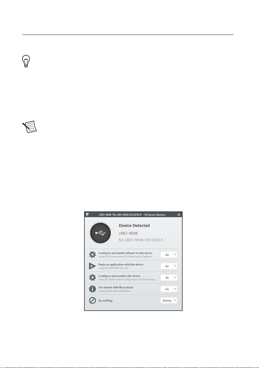
The device driver software automatically detects the cRIO-904x. Select Configure and
install software to this device.
If the device driver software does not detect the cRIO-904x, verify that you installed the
appropriate NI software in the correct order on the host computer as described in
"Installing Software on the Host Computer" in the cRIO-904x Getting Started Guide.
cRIO-904x User Manual | © National Instruments | 3
Page 4
Connecting the cRIO-904x to the Host Computer or Network Using Ethernet
Complete the following steps to connect the cRIO-904x to a host computer or Ethernet
network using the RJ-45 Gigabit Ethernet port 0. NI recommends using the RJ-45 Gigabit
Ethernet port 0 for communication with deployed systems.
Note You can configure the RJ-45 Gigabit Ethernet port 1 in Measurement &
Automation Explorer (MAX) under the Network Settings tab.
1. Power on the host computer or Ethernet hub.
2. Connect the RJ-45 Gigabit Ethernet port 0 on the cRIO-904x to the host computer or
Ethernet hub using a standard Category 5 (CAT-5) or better shielded, twisted-pair
Ethernet cable.
Notice To prevent data loss and to maintain the integrity of your Ethernet
installation, do not use a cable longer than 100 m (328 ft).
The cRIO-904x attempts to initiate a DHCP network connection the first time you
connect using Ethernet. The cRIO-904x connects to the network with a link-local IP
address with the form 169.254.x.x if it is unable to initiate a DHCP connection.
Finding the cRIO-904x on the Network (DHCP)
Complete the following steps to find the cRIO-904x on a network using DHCP.
1. Disable secondary network interfaces on the host computer, such as a wireless access
card on a laptop.
2. Ensure that any anti-virus and firewall software running on the host computer allows
connections to the host computer.
Note MAX uses UDP on port 44525. Refer to the documentation of your
firewall software for information about configuring the firewall to allow
communication through this port.
3. Launch MAX on the host computer.
4. Expand Remote Systems in the configuration tree and locate your system.
Tip MAX lists the system under the model number followed by the serial
number, such as NI-cRIO-904x-1856AAA.
Tip If you do not see the cRIO-904x under Remote Systems, use the
Troubleshoot Remote System Discovery utility to walk through
troubleshooting steps.
Configuring Startup Options
Complete the following steps to configure the cRIO-904x startup options in MAX.
1. In MAX, expand your system under Remote Systems.
2. Select the Startup Settings tab to configure the startup settings.
4 | ni.com | cRIO-904x User Manual
Page 5
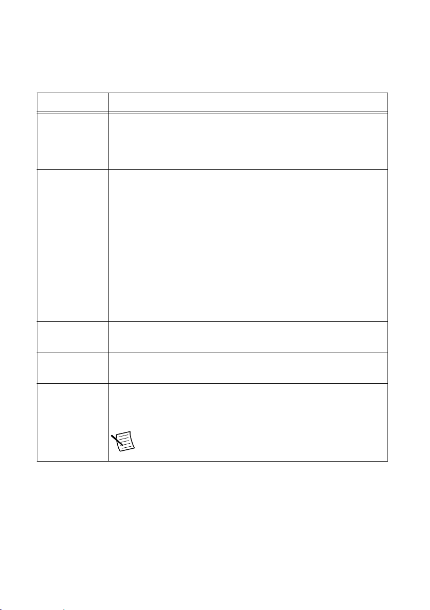
cRIO-904x Startup Options
You can configure the following cRIO-904x startup options.
Table 1. cRIO-904x Startup Options
Startup Option Description
Force Safe Mode Rebooting the cRIO-904x with this setting on starts the cRIO-904x
without launching LabVIEW Real-Time or any startup applications. In
safe mode, the cRIO-904x launches only the services necessary for
updating configuration and installing software.
Enable Console
Out
Disable RT
Startup App
Disable FPGA
Startup App
Enable Secure
Shell (SSH)
Logins
Rebooting the cRIO-904x with this setting on redirects the console output
to the RS-232 serial port. You can use a serial-port terminal program to
read the IP address and firmware version of the cRIO-904x. Use a nullmodem cable to connect the RS-232 serial port to a computer. Make sure
that the serial-port terminal program is configured to the following
settings:
• 115,200 bits per second
• Eight data bits
• No parity
• One stop bit
• No flow control
Rebooting the cRIO-904x with this setting on prevents any LabVIEW
startup applications from running.
Rebooting the cRIO-904x with this setting on prevents autoloading of any
FPGA application.
Rebooting the cRIO-904x with this setting on starts sshd on the
cRIO-904x. Starting sshd enables logins over SSH, an encrypted
communication protocol.
Note Visit ni.com/info and enter the Info Code openssh for
more information about SSH.
cRIO-904x User Manual | © National Instruments | 5
Page 6
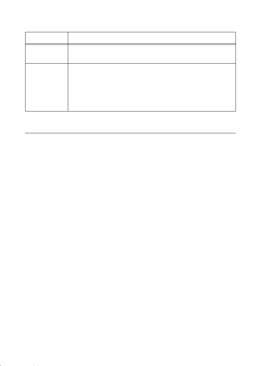
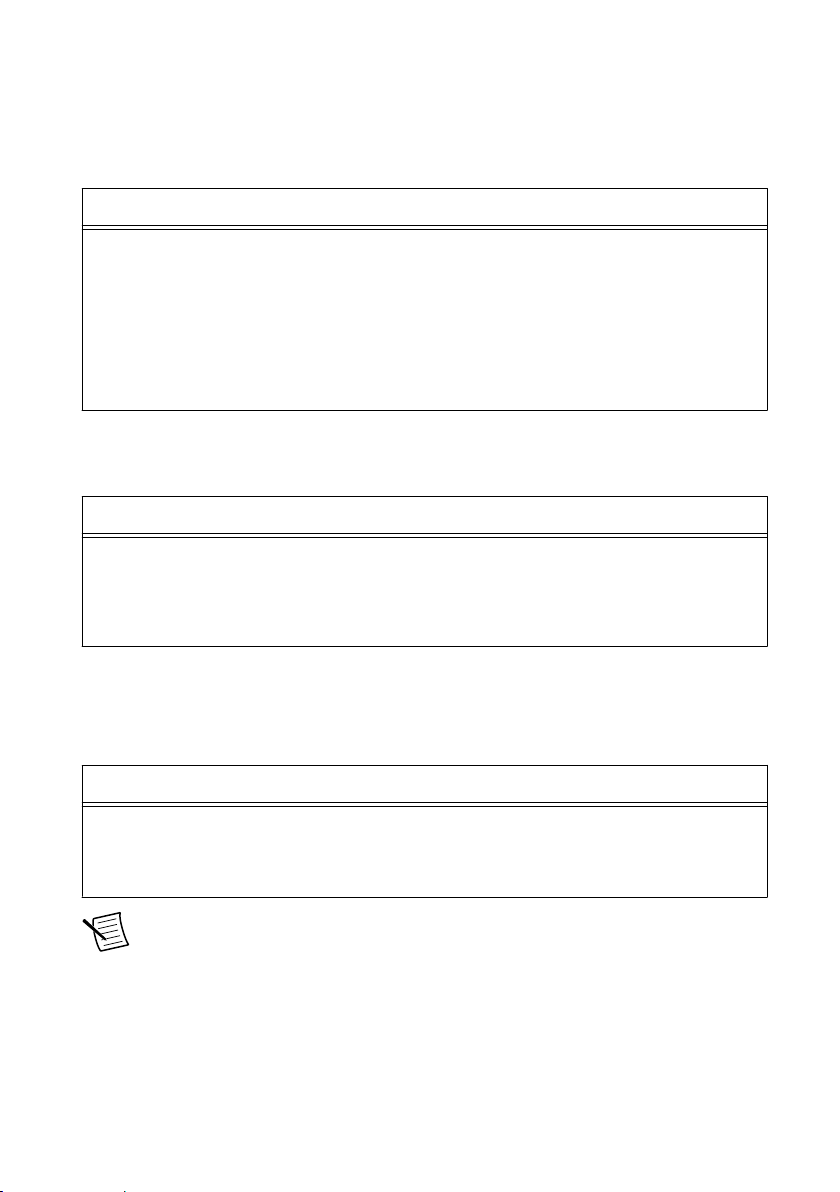
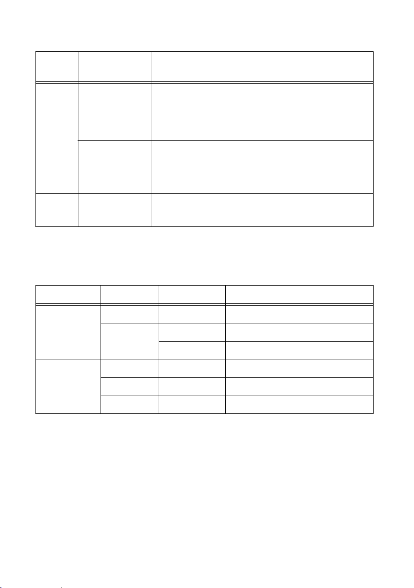
Table 1. cRIO-904x Startup Options (Continued)
Startup Option Description
LabVIEW
Project Access
Enable
Embedded UI
Rebooting the cRIO-904x with this setting on enables you to add the
target to a LabVIEW project.
Rebooting the cRIO-904x with this setting on enables the embedded UI,
which allows you to interact with the front panels of VIs running on the
cRIO-904x using input and display devices connected directly to the
cRIO-904x. You can also browse and edit files on the cRIO-904x within a
graphical working environment. For more information, refer to the Using
the Embedded UI to Access RT Target VIs topic in the LabVIEW Help.
cRIO-904x Features
The cRIO-904x provides the following features.
Ports and Connectors
The cRIO-904x provides the following ports and connectors.
6 | ni.com | cRIO-904x User Manual
Page 7
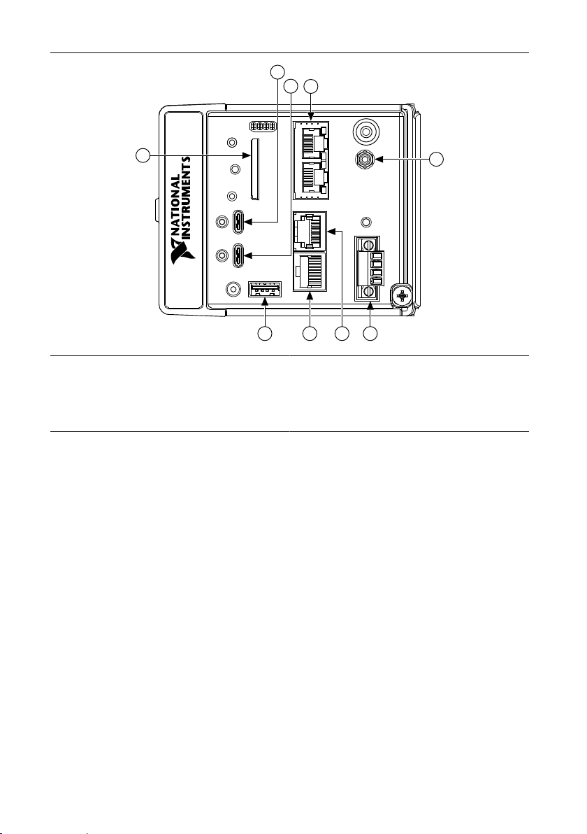
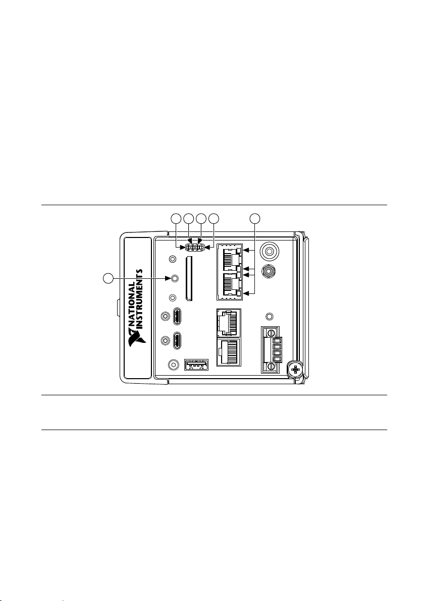
Figure 1. cRIO-904x Ports and Connectors
9
1
2
3
4
5
6
7
8
1. USB 3.1 Type-C Dual Role
2. USB 3.1 Type-C with DisplayPort Alt Mode
3. RJ-45 Gigabit Ethernet Ports
4. PFI 0
5. Power Connector
6. RS-232 Serial Port
7. RS-485 Serial Port
8. USB 2.0 Type-A
9. SD Card Removable Storage
USB 3.1 Type-C Dual Role
The USB 3.1 Type-C Dual Role port implements dual role functionality and is capable of
functioning as either a USB 3.1 Gen1 host or device. When operating as a host, the port
supports common USB devices such as mass-storage devices, keyboards, mice, and USB
cameras. When operating a device, use this port to connect the cRIO-904x to a host PC. The
USB device functionality provides an alternate method to connect the cRIO-904x to a host PC
and is intended for configuration, application deployment, debugging, and maintenance. The
role of the port is determined automatically based on the cable inserted into the port. For
example, the port will automatically function as a device when the cRIO-904x is connected to
a host PC using the NI USB Type-C male to Type-A male cable provided in the kit.
USB 3.1 Type-C with DisplayPort Alt Mode
The USB 3.1 Type-C with DisplayPort Alt Mode port implements both a USB 3.1 Gen1 host
and a DisplayPort 1.2 source using the USB Type-C DisplayPort alternate mode. Use a USB
Type-C video adapter or monitor supporting the DisplayPort alternate mode to use this port as
a display output. Alternatively, this port may be used as a standard USB host port and supports
common USB devices such as mass-storage devices, keyboards, mice, and USB cameras. Use
a USB Type-C male to USB Type-A female adapter to use this port with USB devices
cRIO-904x User Manual | © National Instruments | 7
Page 8
implementing a type-A male connector. Use a USB Type-C multiport adapter to
simultaneously use this port as a display output and a USB host port.
The following NI USB Type-C adapters are available for the cRIO-904x.
Table 2. NI USB Type-C Adapters for cRIO-904x
Adapter Length Part Number
USB to DVI Adapter with Retention, USB Type-C Male to DVI-D
0.5 m 143558-0R5
Female
USB to VGA Adapter with Retention, USB Type-C Male to VGA
0.5 m 143557-0R5
Female
USB Cable with Retention, Type-C Male to Type-A Female, USB
0.5 m 143555-0R5
3.1, 3A
The following NI USB Type-C cables with retention are available for the cRIO-904x.
Table 3. NI USB Type-C Cables for cRIO-904x
Cable Length Part Number
USB Cable with Retention, Type-C Male to Type-C Male, USB 3.1,3A0.3 m 143556-0R3
1 m 143556-01
1 m 143556-02
PFI 0
The Programmable Function Interface (PFI) terminal is a SMB connector.
Table 4. Signal Descriptions
Signal Reference Description
PFI 0 — Programmable Function Interface—You can configure the PFI terminal
as a timing input or timing output signal for AI, AO, DI, DO, or
counter/timer functions.
Note The PFI 0 terminal can only be programmed with NI-DAQmx.
Power Connector
The cRIO-904x has a power connector to which you can connect a primary and secondary
power supply. The following table shows the pinout for the power connector.
8 | ni.com | cRIO-904x User Manual
Page 9
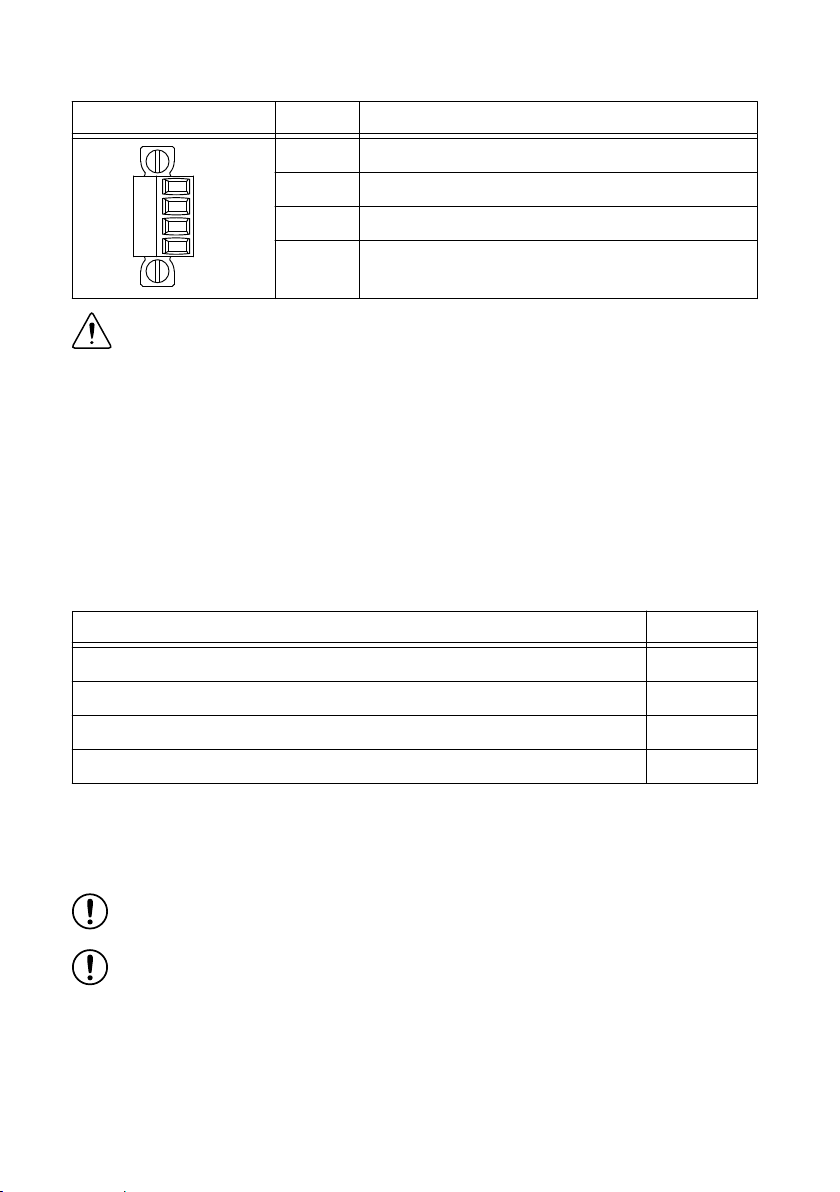
Table 5. Power Connector Pinout
V1
C
V2
C
Pinout Pin Description
V1 Primary power input
C Common
V2 Secondary power input
C Common
Caution The C terminals are internally connected to each other, but are
functionally isolated from chassis ground. This isolation is intended to prevent
ground loops, but does not meet IEC 61010-1 for safety isolation. You can connect
the C terminals to chassis ground externally. Refer to the specifications on ni.com/
manuals for information about the power supply input range and maximum voltage
from terminal to chassis ground.
If you apply power to both the V1 and V2 inputs, the cRIO-904
x operates from the V1 input.
If the input voltage to V1 is insufficient, the cRIO-904x operates from the V2 input.
The cRIO-904x has reverse-voltage protection.
The following NI power supplies and accessories are available for the cRIO-904x.
Table 6. Power Accessories
Accessory Part Number
NI PS-15 Power Supply, 24 VDC, 5 A, 100-120/200-240 VAC Input 781093-01
NI PS-10 Desktop Power Supply, 24 VDC, 5 A, 100-120/200-240 VAC Input 782698-01
4-Position Gold Power Supply Plugs (Quantity 5) 783529-01
NI 9979 Strain Relief for 4-Position Power Connector 196939-01
SD Card Removable Storage
The cRIO-904x provides an SD card slot that can read from and write to SD cards. The slot
supports SD card interface speeds up to UHS-I DDR50.
Notice Using SD cards that are not approved by NI might invalidate specifications
and result in unreliable performance.
Notice Full and high-speed SD cards are prohibited for use with the cRIO-904x.
The following accessories are available from the SD card slot.
cRIO-904x User Manual | © National Instruments | 9
Page 10
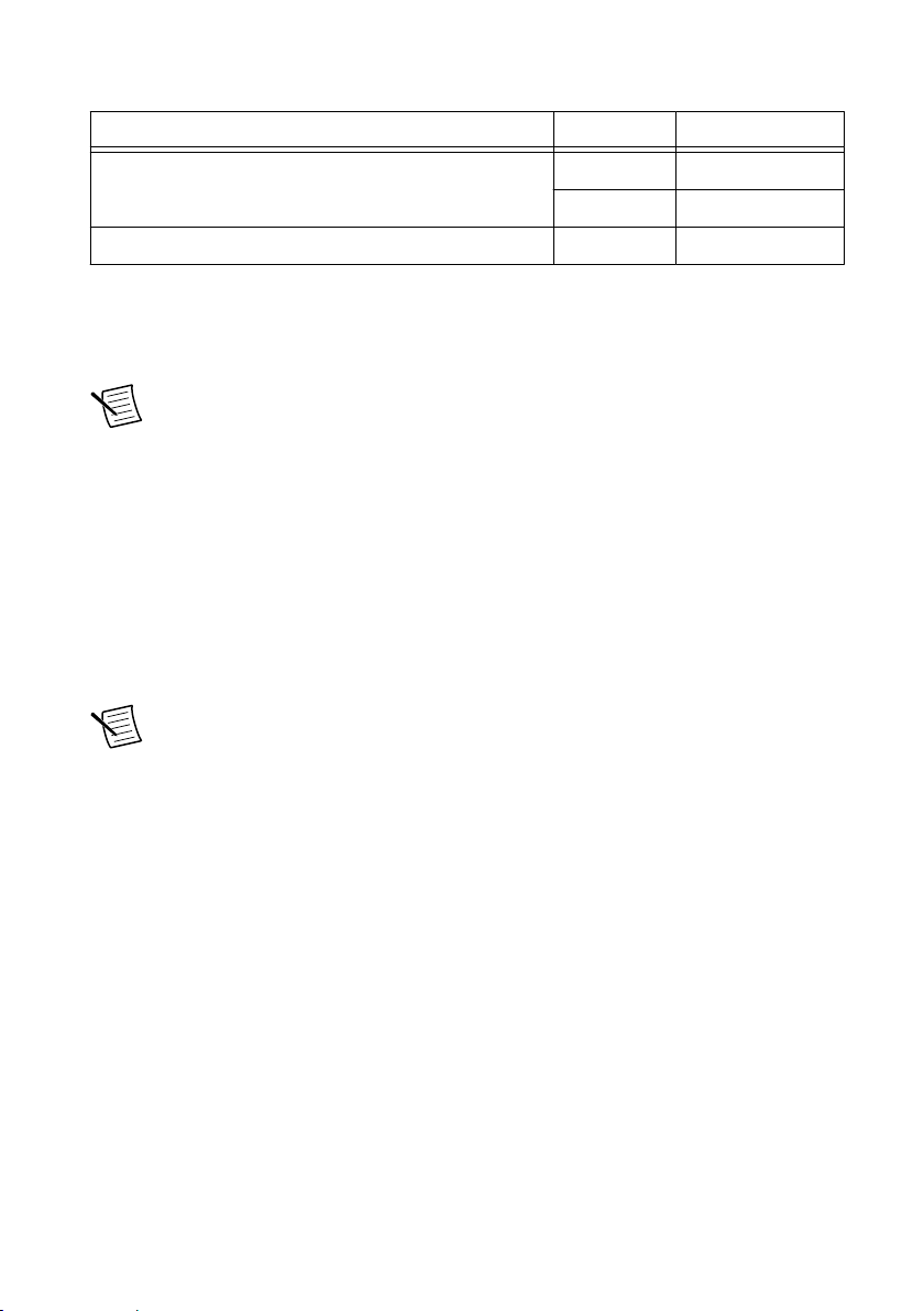
Table 7. cRIO-904x SD Storage Accessories
SD Card Capacity Part Number
Industrial SD Card, -40 to 85 °C, UHS-I 16 GB 786362-01
32 GB 786363-01
SD Door (x3) - 786218-01
SD Card Slot Cover
You must use the SD card slot cover to protect the SD card in hazardous locations. Do not
remove an SD card while either LED is flashing or lit because file corruption may result.
Note Screw the slot cover closed completely. Tighten the captive screws to a
maximum torque of 0.75 N · m (6.7 lb · in.) using a #1 Phillips screwdriver. Do not
overtighten.
RS-232 Serial Port
The cRIO-904x has an RS-232 serial port that is implemented with an RJ-50, 10-position
modular jack to which you can connect devices such as displays or input devices. Use the
Serial VIs to read from and write to the serial port. Refer to the LabVIEW Help for information
about the Serial VIs.
Find examples on how to use NI-Serial or NI-VISA to perform serial communication in the
NI Example Finder. The NI Example Finder is located on the Help menu in the LabVIEW
Help.
Note The RS-232 serial port cannot be accessed by the user application when the
Console Out startup option is enabled.
The following table shows the pinout for the RS-232 serial port.
10 | ni.com | cRIO-904x User Manual
Page 11
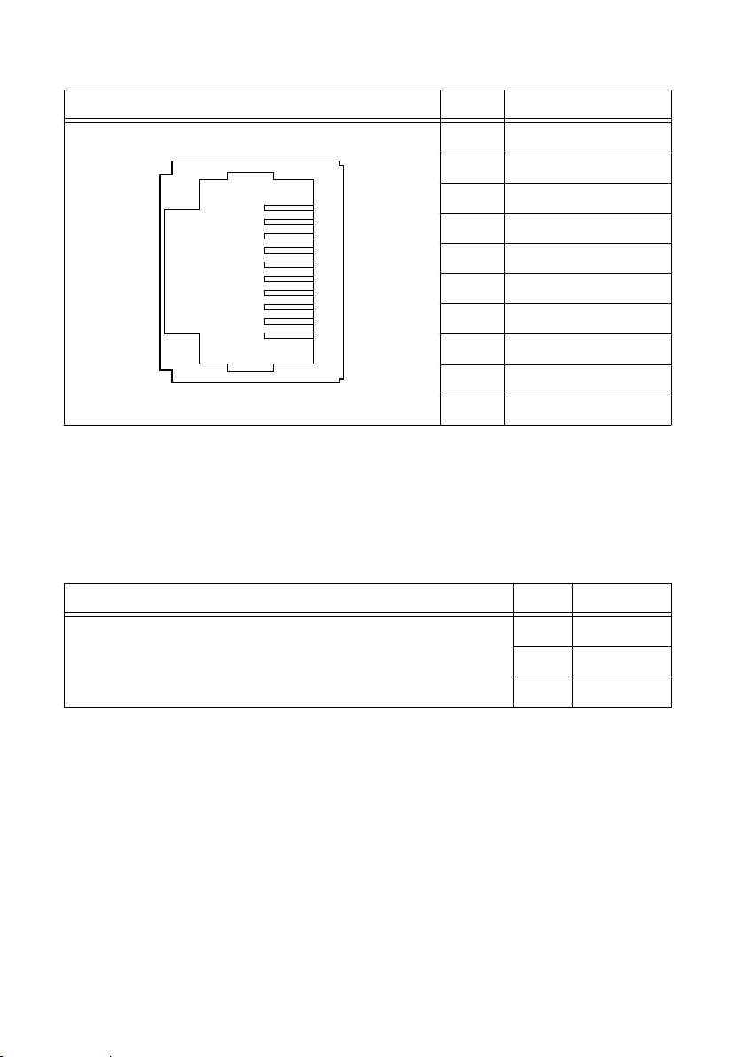
Table 8. RS-232 Serial Port Pinout
3
4
5
6
7
8
9
10
1
2
Pinout Pin Signal
1 No Connect
2 RI
3 CTS
4 RTS
5 DSR
6 GND
7 DTR
8 TXD
9 RXD
10 DCD
You can use the Ring Indicator (RI) on pin 2 to wake the controller from a low-power state.
You can drive RI with a logic level high to wake the cRIO-904x. Refer to the specifications on
ni.com/manuals for the RI wake voltage.
The following accessories are available to connect the RS-232 serial port to a 9-pin DSUB
plug.
Table 9. RS-232 Serial Port Accessories
Accessory Length Part Number
RS-232, S8 Serial Cable, 10-Position Modular Plug to 9-Pin DSUB 1 m 182845-01
2 m 182845-02
3 m 182845-03
RS-485 Serial Port
The cRIO-904x has an RS-485 serial port that is implemented with an RJ-50, 10-position
modular jack. The RJ-50 connector is isolated from the cRIO-904x. For more information
about the electrical isolation of the RS-485 port, refer to the specifications on ni.com/manuals.
Find examples on how to use NI-Serial or NI-VISA to perform serial communication in the
NI Example Finder. The NI Example Finder is located on the Help menu in the LabVIEW
Help.
The following table shows the pinout for the RS-485 serial port.
cRIO-904x User Manual | © National Instruments | 11
Page 12
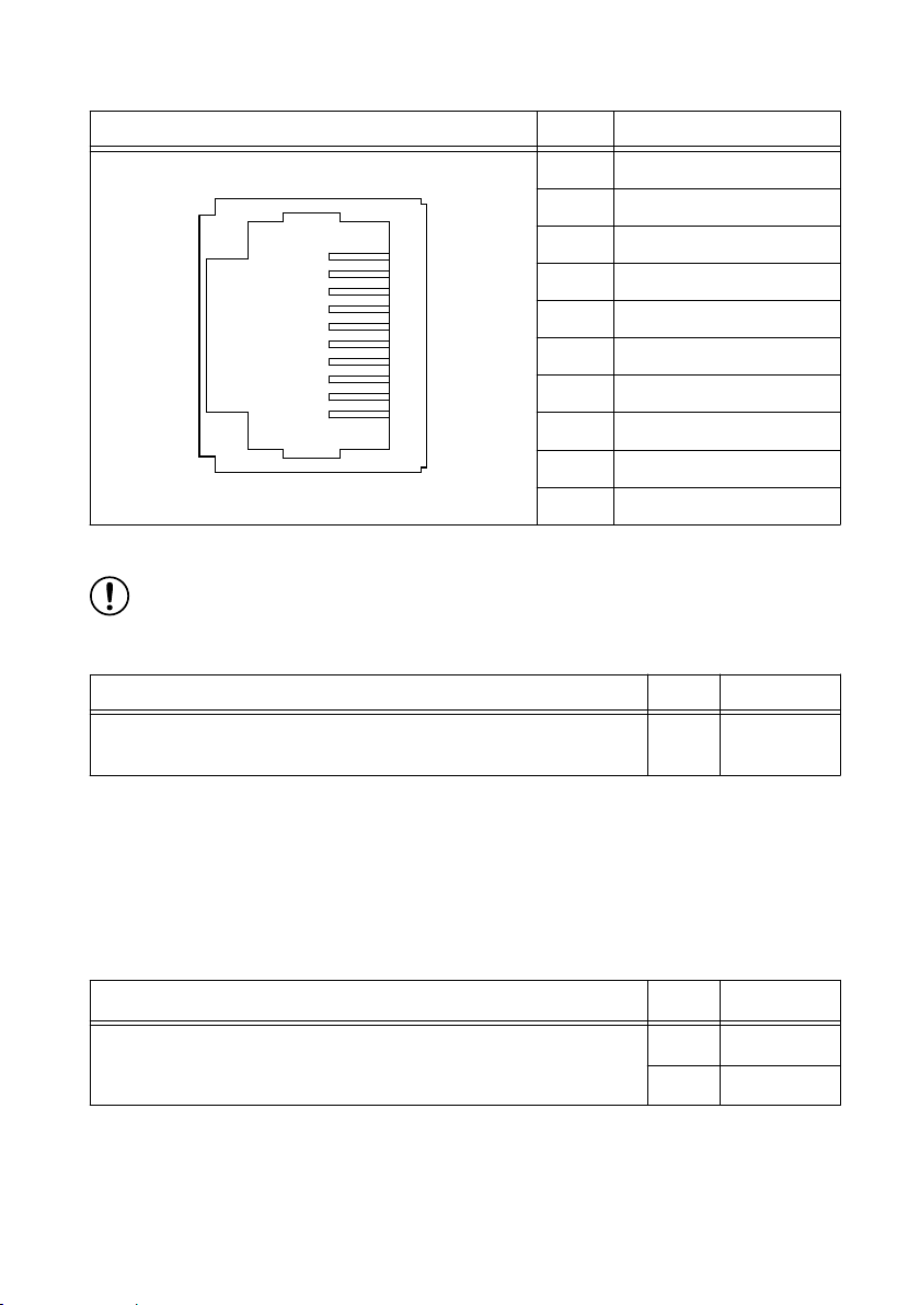
Table 10. RS-485 Serial Port Pinout
3
4
5
6
7
8
9
10
1
2
Pinout Pin Signal
1 No Connect
2 TXD-
3 TXD+
4 No Connect
5 No Connect
6 RXD-
7 RXD+
8 No Connect
9 No Connect
10 Isolated GND
The following accessory is available to connect the RS-485 serial port to a 9-pin DSUB plug.
Notice To ensure the specified EMC performance, you must use an isolated cable
with the RS-485 serial port. The following accessory meets this requirement.
Table 11. RS-485 Serial Port Accessory
Accessory Length Part Number
RS-485, S8 Serial Cable, 10-Position Modular Plug to 9-Pin DSUB
1 m 184428-01
(Isolated)
USB 2.0 Type-A
The USB 2.0 Type-A port implements a USB 2.0 Type-A host and supports common USB
devices such as mass-storage, devices, keyboards, mice, and USB cameras.
The following NI cables with retention are available for the cRIO-904x.
Table 12. NI Cables with Retention for cRIO-904x
Cable Length Part Number
USB Extension with Retention, Type-A Male to Type-A Female,
USB 2.0
Buttons
The cRIO-904x provides the following buttons.
12 | ni.com | cRIO-904x User Manual
0.5 m 152166-0R5
2 m 152166-02
Page 13
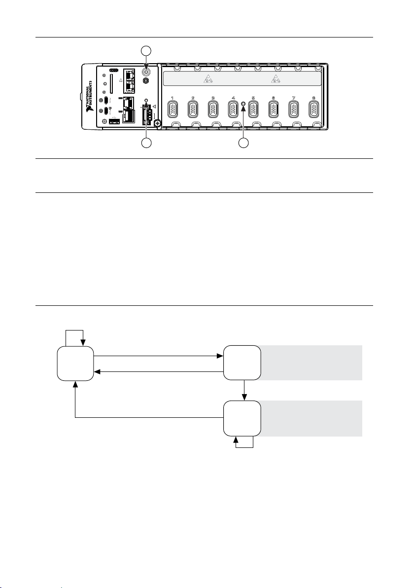
Figure 2. cRIO-904x Buttons
10/100
USER1
1: POWER
2: STATUS
3:
1 2 3 4
4:USER
FPGA1
/1000
ACT/
SYNC
PUSH TO EJECT
SD
IN USE
DUAL ROLEHOST
RS-232
RESET
PFI 0
USER1
INPUT
9–30 V
V1
V1
C
C
V2
V2
C
DO NOT SEPARATE CONNECTORS WHEN
ENERGIZED IN HAZARDOUS LOCATIONS
60 W MAX
RS-485
1
0
LINK
10/100
/1000
ACT/
LINK
DP
1
32
Press and hold RESET button for ≥ 5 s
Press and hold RESET button for < 5 s
Run Mode
Safe Mode
Press and hold RESET button for < 5 s
Press and hold RESET button for ≥ 5 s
Press and hold
RESET button for ≥ 5 s
Press and hold
RESET button for < 5 s
• Console Out enabled
• Network settings reset
• RT Startup App disabled
• FPGA Startup App disabled
• Console Out enabled
• RT Startup App disabled
• FPGA Startup App disabled
Safe Mode
1. USER1 Button
2. RESET Button
3. CMOS Reset Button
USER1 Button
The cRIO-904x has a general-purpose USER1 button that is user-defined. You can read the
state of the USER1 button from your LabVIEW FPGA application.
RESET Button
Press the RESET button to reset the processor in the same manner as cycling power.
The following figure shows the reset behavior of the cRIO-904x.
Figure 3. Reset Button Behavior
For more information about using the RESET button for network troubleshooting, see
Troubleshooting Network Connectivity.
cRIO-904x User Manual | © National Instruments | 13
Page 14
Troubleshooting Network Connectivity
6
1
2
3
4
5
You can use the RESET button to troubleshoot network connectivity.
Complete the following steps to reset the network adapters to default settings.
1. Hold the RESET button for 5 seconds, and then release it to boot the controller in safe
mode and enable Console Out.
2. Hold the RESET button again for 5 seconds to boot the controller into safe mode, enable
Console Out, and reset network adapters to default settings.
CMOS Reset Button
The cRIO-904x has a CMOS reset button that you can use to reset the CMOS and the BIOS.
LEDs
Learn more about the LEDs for your cRIO-904x.
Figure 4. cRIO-904x Front Panel LEDs
1. POWER LED
2. STATUS LED
3. USER1 LED
4. USER FPGA1 LED
5. Gigabit Ethernet LEDs
6. SD In Use LED
POWER LED Indicators
The POWER LED on the cRIO-904x indicates which power input is in use, as shown in the
following table.
14 | ni.com | cRIO-904x User Manual
Page 15

Table 13. POWER LED Indicators
LED Color LED Pattern Indication
Green Solid The cRIO-904x is powered from the V1 input.
Yellow Solid The cRIO-904x is powered from the V2 input.
— Off The cRIO-904x is powered off.
For more information about connecting the cRIO-904x to power, refer to "Connecting the
Controller to Power" in the cRIO-904x Getting Started Guide .
STATUS LED Indicators
The following table describes the STATUS LED indicators.
cRIO-904x User Manual | © National Instruments | 15
Page 16

LED
Color
Table 14. STATUS LED Indicators
LED Pattern Indication
Yellow Blinks twice and
pauses
Blinks three times
and pauses
Blinks four times
and pauses
Continuously
blinks
The cRIO-904x is in safe mode. Software is not installed,
which is the factory default state, or software has been
improperly installed on the cRIO-904x.
An error can occur when an attempt to upgrade the software
is interrupted. Reinstall software on the cRIO-904x. Refer to
"Installing Software on the Controller" in the cRIO-904x
Getting Started Guide for information about installing
software on the cRIO-904x.
The cRIO-904x is in user-directed safe mode, or the
cRIO-904x is in install mode to indicate that software is
currently being installed.
This pattern may also indicate that the user has forced the
cRIO-904x to boot into safe mode by pressing the reset
button for longer than five seconds or by enabling safe mode
in MAX. Refer to the RESET Button for information about
safe mode.
The cRIO-904x is in safe mode. The software has crashed
twice without rebooting or cycling power between crashes.
The cRIO-904x has not booted into NI Linux Real-Time.
The cRIO-904x either booted into an unsupported operating
system, was interrupted during the boot process, or detected
an unrecoverable software error.
On momentarily The cRIO-904x is booting. No action required.
16 | ni.com | cRIO-904x User Manual
Page 17
LED
Color
Table 14. STATUS LED Indicators (Continued)
LED Pattern Indication
Red Continuously
blinks
This indicates a hardware error. An internal power supply
has failed. Check front-panel I/O and C Series module
connections for shorts. Remove any shorts and cycle power
the cRIO-904x. If the problem persists, contact NI.
Solid The cRIO-904x internal temperature has exceeded a critical
threshold. Ensure the ambient operating temperature does
not exceed the specified operating temperature. If the
problem persists, contact NI.
— Off The cRIO-904x is in run mode. Software is installed and the
operating system is running.
Ethernet LED Indicators
The following table lists the Ethernet LED indicators.
Table 15. Ethernet LED Indicators
LED LED Color LED Pattern Indication
ACT/LINK - Off LAN link not established
Green Solid LAN link established
Flashing Activity on LAN
10/100/1000 Yellow Solid 1,000 Mbit/s data rate selected
Green Solid 100 Mbit/s data rate selected
- Off 10 Mbit/s data rate selected
SD In Use LED Indicator
The cRIO-904x has a SD In Use LED to indicate the card drive mount status. The following
table lists details of the SD In Use LED indicator.
cRIO-904x User Manual | © National Instruments | 17
Page 18
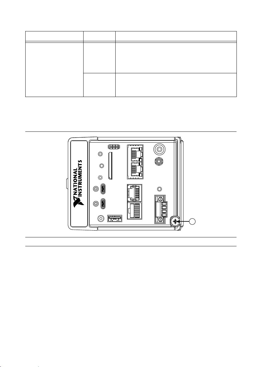
Table 16. SD In Use LED Indicator
1
LED LED Color LED Pattern Indication
SD IN USE Green Off There is no SD card present in the slot or the
cRIO-904x has unmounted the SD card from the
operating system. It is safe to remove the SD card
from the slot.
Solid The SD card in the slot is mounted in the operating
system. Do not remove the SD card while this LED
is lit.
Chassis Grounding Screw
The cRIO-904x provides a chassis grounding screw.
Figure 5. cRIO-904x Chassis Grounding Screw
1. Chassis Grounding Screw
For information about grounding the cRIO-904
cRIO-904x Getting Started Guide.
For more information about ground connections, visit ni.com/info and enter the Info Code
emcground.
x, see "Grounding the Controller" in the
Internal Real-Time Clock
The cRIO-904x contains an internal real-time clock that maintains system time when the
cRIO-904x is powered off. The system clock of the cRIO-904x is synchronized with the
internal real-time clock at startup. You can set the real-time clock using the BIOS setup utility
or MAX, or you can set the real-time clock programmatically using LabVIEW.
18 | ni.com | cRIO-904x User Manual
Page 19
Refer to the model specifications on ni.com/manuals for the real-time clock accuracy
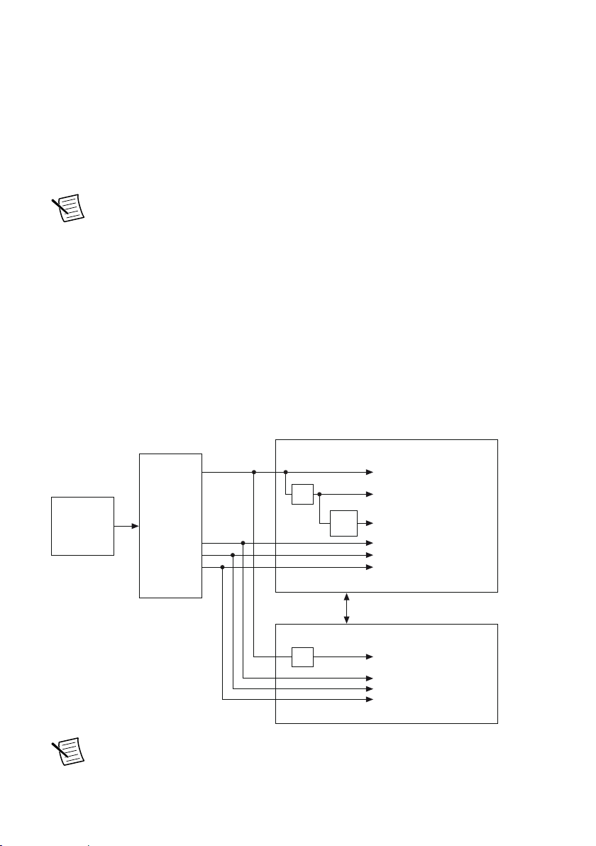
Onboard
100 MHz
Oscillator
Clock
Generator
DAQ ASIC
RIO FPGA
cRIO Trigger Bus
80 MHz Timebase
20 MHz Timebase
100 kHz Timebase
13.1072 MHz Timebase
12.8 MHz Timebase
10 MHz Timebase
40 MHz Onboard Clock
÷200
13.1072 MHz Carrier Clock
12.8 MHz Carrier Clock
10 MHz Carrier Clock
÷2
÷4
specifications.
Digital Routing
The digital routing circuitry of the cRIO-904x manages the flow of data between the bus
interface and the acquisition and generation sub-systems when programming C Series modules
in Real-Time (NI-DAQmx) mode. The subsystems include analog input, analog output, digital
I/O, and counters. The digital routing circuitry uses FIFOs (if present) in each sub-system to
ensure efficient data movement.
Note When programming C Series modules in FPGA mode, the flow of data
between the modules and the bus interface is programmed using LabVIEW FPGA.
The digital routing circuitry also routes timing and control signals. The acquisition and
generation sub-systems use these signals to manage and synchronize acquisitions and
generations. These signals can come from the following sources:
• C Series modules programmed in Real-Time (NI-DAQmx) mode
• User input through the PFI terminals using parallel digital C Series modules or the
cRIO-904x PFI 0 terminal
• FPGA or DAQ ASIC using the cRIO trigger bus to share hardware triggers and signals
between the LabVIEW FPGA and DAQmx applications
Clock Routing
The following figure shows the clock routing circuitry of the cRIO-904x.
Figure 6. Clock Routing Circuitry of the cRIO-904x
Note When switching between programming modes, you may notice the terms
timebase and clock used interchangeably. This is due to the DAQ ASIC and the RIO
cRIO-904x User Manual | © National Instruments | 19
Page 20

FPGA using different terminology for timing and clock mechanisms. The
documentation will use the term based on the programming mode discussed.
80 MHz Timebase
When programming C Series modules in Real-Time (NI-DAQmx) mode, the 80 MHz
timebase can function as the source input to the 32-bit general-purpose counter/timers. The
80 MHz timebase is generated from the onboard oscillator.
20 MHz and 100 kHz Timebases
When programming C Series modules in Real-Time (NI-DAQmx) mode, the 20 MHz and
100 kHz timebases can be used to generate many of the analog input and analog output timing
signals. These timebases can also function as the source input to the 32-bit general-purpose
counter/timers. The 20 MHz and 100 kHz timebases are generated by dividing down the
80 MHz timebase, as shown in the previous figure.
40 MHz Onboard Clock
When programming C Series modules in FPGA mode, the 40 MHz onboard clock is used as
the top-level clock for your LabVIEW FPGA application and C Series module IO nodes. The
40 MHz onboard clock can be used to clock single-cycle timed loops. Derived clocks of
varying frequency can be generated from the 40 MHz onboard clock. The 40 MHz onboard
clock is phase aligned with the incoming 80 MHz clock.
13.1072 MHz, 12.8 MHz, and 10 MHz Timebases and Carrier Clocks
When programming C Series modules in Real-Time (NI-DAQmx) mode, the 13.1072 MHz,
12.8 MHz, and 10 MHz timebases can be used to generate many of the analog input and
analog output timing signals. These timebases can also function as the source input to the 32bit general-purpose counter/timers. The 13.1072 MHz, 12.8 MHz, and 10 MHz timebases are
generated directly from the onboard clock generator.
When programming C Series modules in FPGA mode, the 13.1072 MHz, 12.8 MHz, and
10 MHz carrier clocks can be used as the master clock for C Series analog input and analog
output modules. The 13.1072 MHz, 12.8 MHz, and 10 MHz carrier clocks are available as IO
Nodes in LabVIEW FPGA applications and can be used to correlate the onboard clocks with
self-timed C Series modules containing free-running clocks.
Synchronization Across a Network
Internal Timebase
The onboard 100 MHz oscillator automatically synchronizes to other network-synchronized
devices that are part of the local IEEE 802.1AS or IEEE 1588-2008 subnet, depending on the
active time reference that is being used on the controller.
The 80 MHz, 40 MHz, 20 MHz, 100 kHz, 13.1072 MHz, 12.8 MHz, and 10 MHz timebases
are derived from the onboard oscillator and are synchronized to it. Therefore, the timebases are
also synchronized to other network-synchronized timebases on the IEEE 802.1AS or
20 | ni.com | cRIO-904x User Manual
Page 21

IEEE 1588-2008 subnet. This enables analog input, analog output, digital I/O, and counter/
timers to be synchronized to other chassis across a distributed network.
When programming C Series modules in FPGA mode, the Time Synchronization IO Nodes
can be used to synchronize the LabVIEW FPGA application to other network-synchronized
devices.
Network-based Synchronization
IEEE 1588, also known as the precision time protocol (PTP), is an Ethernet-based
synchronization method designed for cabled, local networks. The PTP protocol provides a
fault tolerant method of synchronizing all participating clocks to the highest quality clock in
the network. This method of synchronization between networked devices uses packet-based
communication and is possible over the long distances allowed for each Ethernet link, without
signal propagation impact. IEEE 1588 has many different profiles, such as
IEEE 802.1AS-2011, each of which use different features. Because the profiles are not
interoperable with each other, make sure it is known which profile is implemented on the
device. For devices on the network to synchronize with each other using IEEE 1588, all
devices must be compatible with the desired IEEE 1588 profile and must all be connected
within the selected IEEE 1588 profile-compliant network infrastructure.
The cRIO-904x controllers are compatible with both the IEEE 802.1AS-2011 profile and the
IEEE 1588-2008 (1588v2) Delay Request-Response profile. However, each network port must
be configured individually to the specific profile required for the network.
Differences Between IEEE 802.1AS-2011 and IEEE 1588-2008
IEEE 802.1AS-2011, also known as the generalized precision time protocol (gPTP), is a
profile of IEEE 1588. A cRIO-904x controller can be configured to use either the
IEEE 802.1AS-2011 profile or the IEEE 1588-2008 profile by configuring the port’s time
reference. If a user does not explicitly specify which time reference to use a cRIO-904x
controller will default to use the IEEE 802.1AS-2011 profile. There are some differences
between the IEEE 802.1AS-2011 profile and the IEEE 1588-2008 profile which are called out
below:
• IEEE 802.1AS-2011 assumes all communication between devices is done on the OSI
layer 2, while IEEE 1588-2008 can support various layer 2 and layer 3-4 communication
methods. The IEEE 1588-2008 profile National Instruments implements on the
cRIO-904x only supports layer 3-4 communication methods. Operating on the layer 2
yields better performance for the IEEE 802.1AS-2011.
• IEEE 802.1AS-2011 only communicates gPTP information directly with other
IEEE 802.1AS devices within a system. Therefore, there must be IEEE 802.1AS-2011
support along the entire path from one IEEE 802.1AS-2011 device to another. With
IEEE 1588-2008, it is possible to use non-IEEE 1588-2008 switches between two
IEEE 1588-2008 devices. The benefit of having IEEE 802.1AS-2011 support along the
entire path is a faster performance and lower jitter compared to IEEE 1588-2008.
• With IEEE 802.1AS-2011 there are only two types of time-aware systems: time-aware
end stations and time-aware bridges. Whereas with IEEE 1588-2008, there are the
following: ordinary clock, boundary clock, end-to-end transparent clock and a time-aware
bridges. Based on these factors, IEEE 802.1AS-2011 can reduce complexity and
cRIO-904x User Manual | © National Instruments | 21
Page 22

configuration challenges compared to IEEE 1588-2008. A cRIO-904x controller acts as a
time-aware end station for both protocols.
IEEE 1588 External Switch Requirements
To take advantage of the network synchronization features of the cRIO-904x controllers,
ensure that your network infrastructure meets certain requirements depending on which
IEEE 1588 profile is implemented for your application:
• IEEE 802.1AS-2011 support—Automatically enables timebase synchronization and
enables the use of time-based triggers and timestamping between devices across the
network. Synchronization performance will meet NI product specifications.
• IEEE 1588-2008 support—Enables timebase synchronization and enables the use of timebased triggers and timestamping between devices across the network. Synchronization
performance will vary and may not meet NI product specifications. As a default
configuration for IEEE 1588-2008, NI supports the IEEE 1588 Delay Request-Response
profile, using the UDP over IP transport (layer 3-4).
CMOS Battery
The cRIO-904x contains a CMOS battery. The CMOS battery is a lithium cell battery that
stores the system clock information when the cRIO-904x is powered off. There is only a slight
drain on the CMOS battery when power is applied to the cRIO-904x power connector. The rate
at which the CMOS battery drains when power is disconnected depends on the ambient
storage temperature. For longer battery life, store the cRIO-904x at a cooler temperature and
apply power to the power connector. Refer to the specifications for your model on ni.com/
manuals for the expected battery lifetime.
The CMOS BATTERY IS DEAD warning appears onscreen during the power-on self test if the
battery is dead. The cRIO-904x still starts, but the system clock is reset to the date and time of
the BIOS release. The battery is not user-replaceable. If you need to replace the CMOS
battery, contact NI. Refer to the specifications for your model on ni.com/manuals for
information about battery disposal.
Installing the Module Immobilization Accessory
The Module Immobilization accessory ensures that the C Series module latches cannot be
retracted and modules cannot be removed from a system. The Module Immobilization
accessory provides extra system assurance and security when shipping and installing systems,
and prevents accidental removal from a system during operation.
When using the Module Immobilization accessory, NI recommends installing the accessory
prior to mounting the system in any enclosure because the accessory requires tool access to the
top, right, and bottom of the cRIO-904x.
What to Use
• cRIO-904x
• C Series modules
22 | ni.com | cRIO-904x User Manual
Page 23
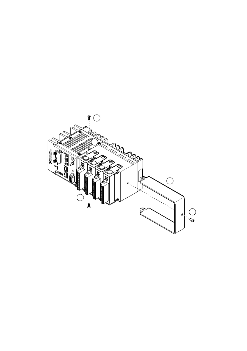
• Module Immobilization accessory kit: 158533-01 for 8-slot models, 158534-01 for 4-slot
5
1
3
4
2
models
– Module immobilization bracket
– Installation screws
1
• M4 x 0.7 button-head screw, 8 mm
• M3 x 0.5 flat-head screws (x2), 10 mm
• Torx T10/T10H driver
• Torx T20/T20H driver
What to Do
Complete the following steps to install the Module Immobilization accessory.
Figure 7. 4-slot cRIO-904x Module Immobilization Accessory Installation
1
The Module Immobilization accessory kit includes two sets of screws. One set is a standard set of
screws that require a standard driver type, Torx T10 and T20. The other set is a tamper-resistant set
of screws that require a security driver type, Torx T10H and T20H. Use the tamper-resistant set to
help prevent unintended modification of the system.
cRIO-904x User Manual | © National Instruments | 23
Page 24
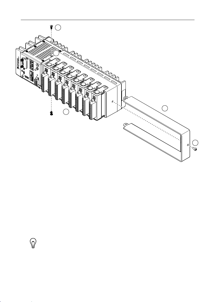
Figure 8. 8-slot cRIO-904x Module Immobilization Accessory Installation
2
5
1
3
4
1. Ensure that all the C Series modules are installed in the cRIO-904x and the latches are
locked in place.
2. Remove the center right panel screw from the top and bottom of the cRIO-904x using the
Torx T10 driver.
3. Slide the bracket into place, aligning the three clearance screw holes.
4. Install the M4 x 0.7 button-head screw in the right end of the cRIO-904x using the
appropriate Torx T20 driver. Tighten the screw to a maximum torque of 1.3 N · m
(11.5 lb · in.).
5. Install the two M3 x 0.5 flat-head screws from the accessory kit in the top and bottom of
the cRIO-904x using the appropriate Torx T10 driver. Tighten the screws to a maximum
torque of 1.3 N · m (11.5 lb · in.).
Tip NI recommends using a liquid thread locker for all fasteners if the system
is expected to experience vibration for an extended amount or time.
Module Immobilization Accessory Dimensions
The following figure shows the Module Immobilization accessory dimensions for the
cRIO-904x.
24 | ni.com | cRIO-904x User Manual
Page 25
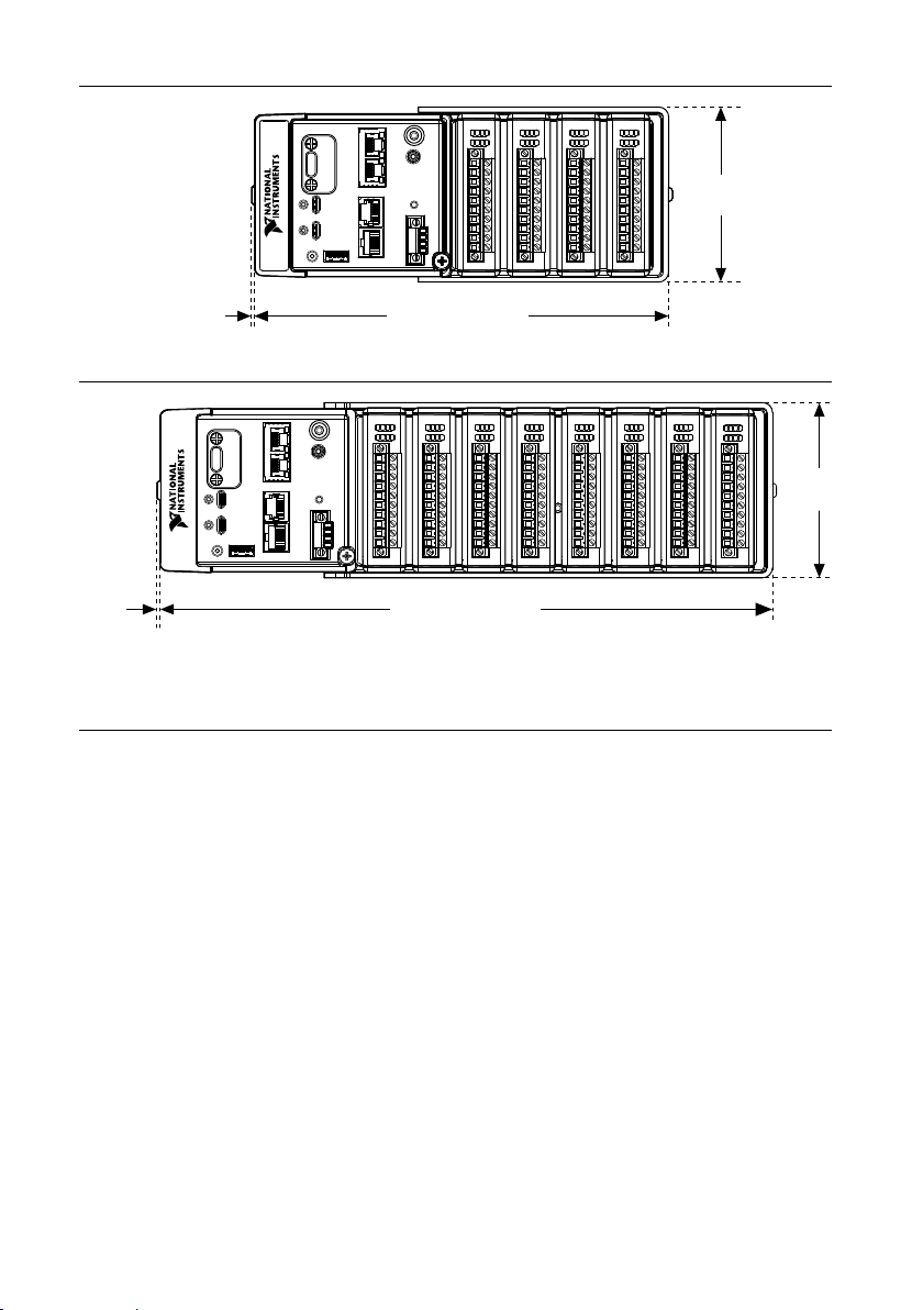
Figure 9. 4-slot cRIO-904x Module Immobilization Accessory Dimensions
94.2 mm
(3.71 in.)
1.6 mm
(0.06 in.)
1.6 mm
(0.06 in.)
220.4 mm (8.68 in.)
329.7 mm (12.98 in.)
1.6 mm
(0.06 in.)
94.2 mm
(3.71 in.)
Figure 10. 8-slot cRIO-904x Module Immobilization Accessory Dimensions
Mounting the Controller
To obtain the maximum ambient temperature, you must mount the cRIO-904x in the reference
mounting configuration shown in the following image. Mounting the cRIO-904x in the
reference mounting configuration ensures that your system will operate correctly across the
full operating temperature range and provide optimal C Series module accuracy. Observe the
following guidelines to mount the cRIO-904x in the reference mounting configuration.
cRIO-904x User Manual | © National Instruments | 25
Page 26
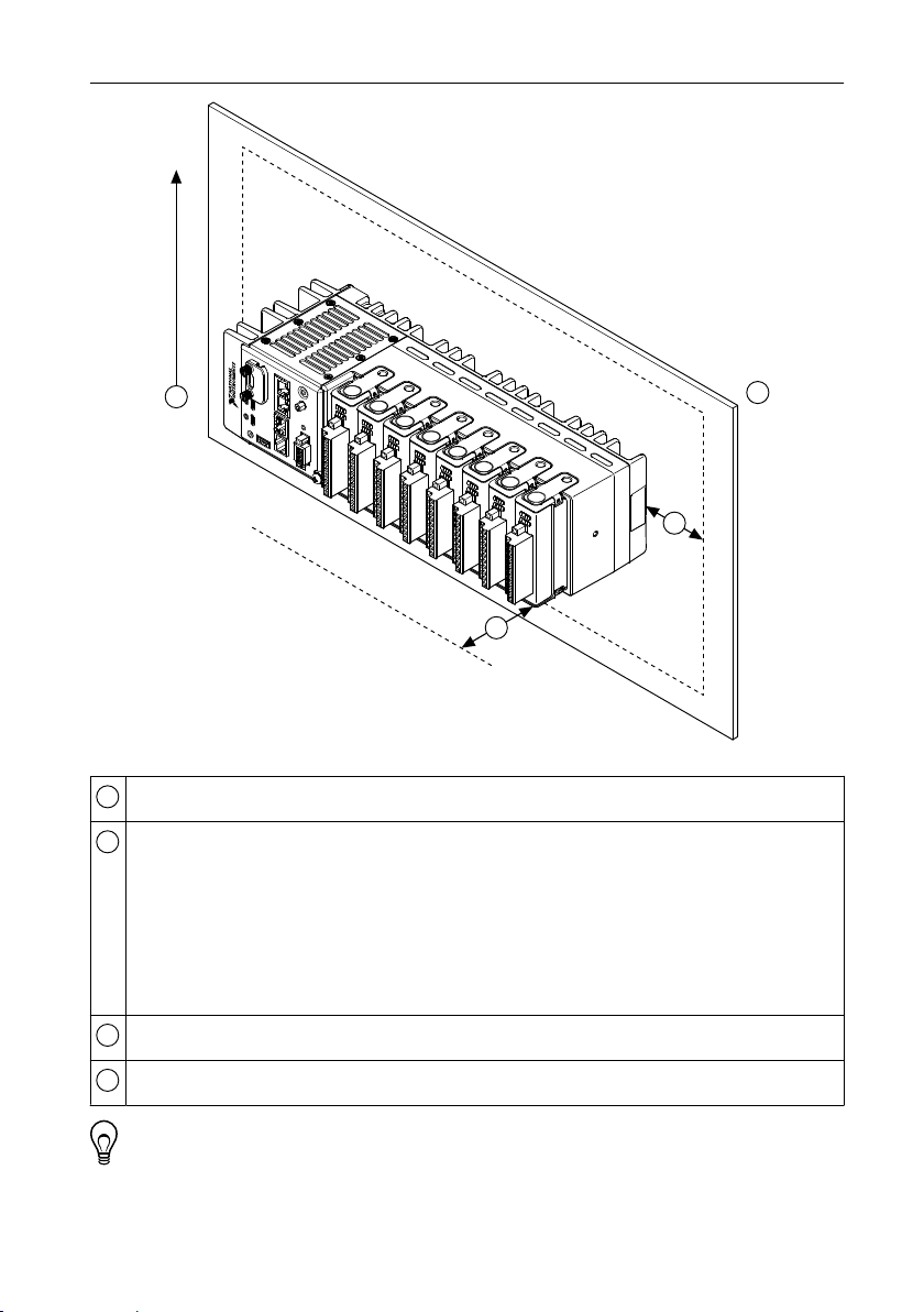
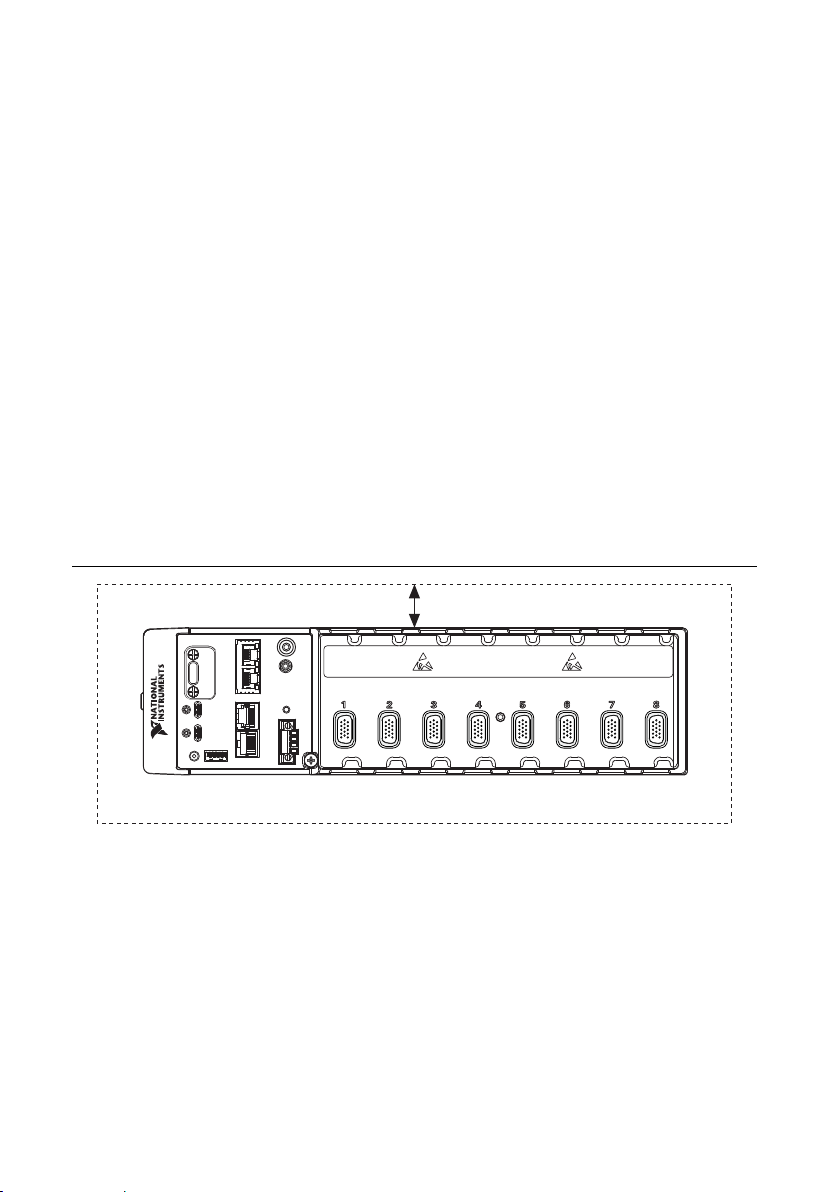
Figure 11. cRIO-904x Reference Mounting Configuration
3
4
1
Up
2
1
2
3
4
Horizontal mounting orientation.
Mounting substrate options:
• Mount the cRIO-904x directly to a metallic surface that is at least 1.6 mm
(0.062 in.) thick and extends a minimum of 101.6 mm (4 in.) beyond all edges of
the device.
• Use the NI Panel Mounting Kit to mount the cRIO-904x to a metallic surface that is
at least 1.6 mm (0.062 in.) thick and extends a minimum of 101.6 mm (4 in.)
beyond all edges of the device.
Observe the cooling dimensions in the Mounting Requirements section.
Allow space for cabling clearance according to the Mounting Requirements section.
Tip Before using any of these mounting methods, record the serial number from
the back of the cRIO-904x so that you can identify the cRIO-904x in MAX. You will
be unable to read the serial number after you mount the cRIO-904x.
26 | ni.com | cRIO-904x User Manual
Page 27
Alternate Mounting Configurations
25.4 mm (1.00 in.)
All Around
Cooling Dimensions
The maximum operating temperature may be reduced for any mounting configuration other
than the reference mounting configuration. A 10 °C (18 °F) reduction in maximum operating
temperature is sufficient for most alternate mounting configurations. Follow the guidelines
above for all mounting configurations.
The published accuracy specifications, although not guaranteed for alternate mounting
configurations, may be met depending on the system power and the thermal performance of
the alternate mounting configuration.
Contact NI for further details regarding the impact of common alternate mounting
configurations on maximum operating temperature and module accuracy.
Mounting Requirements for the cRIO-904x
Use the following to ensure you meet the cooling and cabling clearance requirements for
mounting cRIO-904x models.
Your installation must meet the following requirements for cooling and cabling clearance for
all cRIO-904x models.
Allow 25.4 mm (1.00 in.) on all sides of the cRIO-904x for air circulation, as shown in the
following figure.
Figure 12. cRIO-904x Cooling Dimensions
Allow the appropriate space in front of C Series modules for cabling clearance, as shown in
the following figure. The different connector types on C Series modules require different
cabling clearances. For a complete list of cabling clearances for C Series modules, visit
ni.com/info and enter the Info Code crioconn.
cRIO-904x User Manual | © National Instruments | 27
Page 28
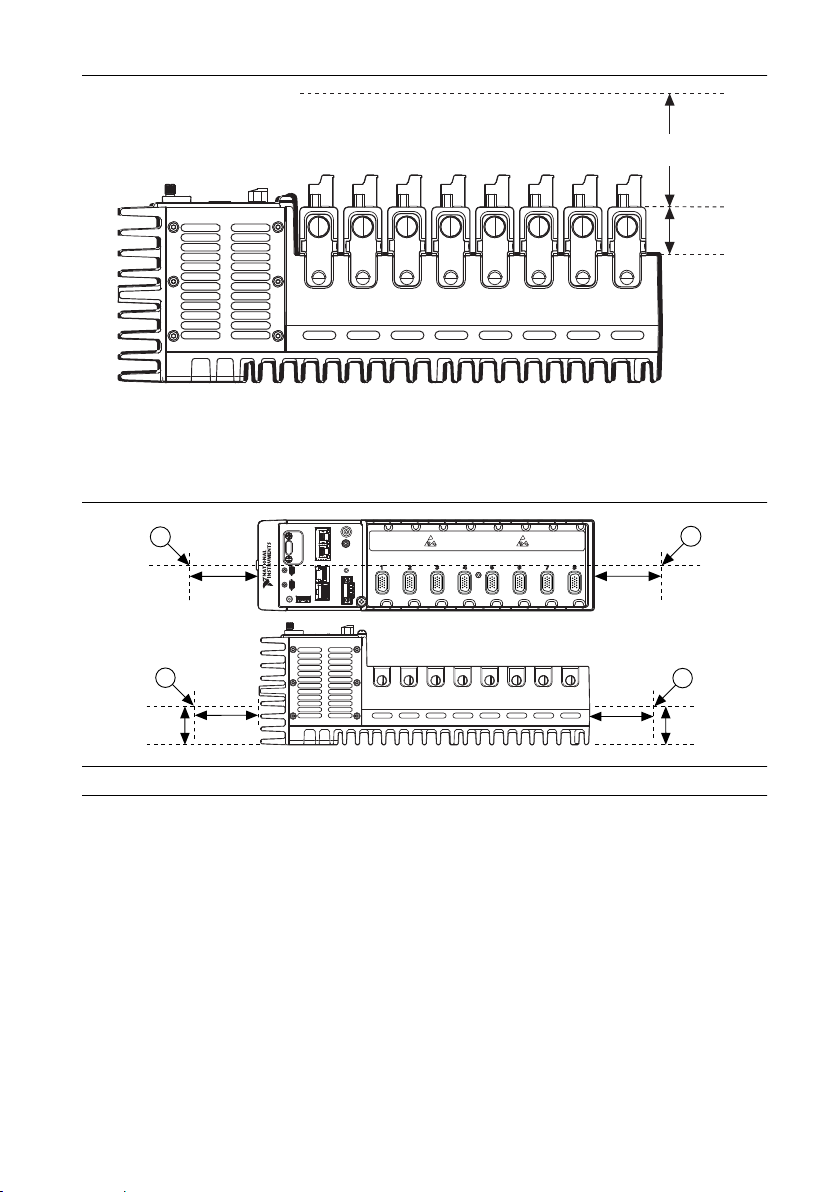
Figure 13. cRIO-904x Cabling Clearance
29.1 mm
(1.14 in.)
Cabling
Clearance
38.1 mm
(1.50 in.)
63.5 mm
(2.50 in.)
1
63.5 mm
(2.50 in.)
1
38.1 mm
(1.50 in.)
63.5 mm
(2.50 in.)
1
63.5 mm
(2.50 in.)
1
Measure the ambient temperature at each side of the cRIO-904x, 63.5 mm (2.50 in.) from the
side and 38.1 mm (1.50 in.) forward from the rear of the cRIO-904x, as shown in the following
figure.
Figure 14. Ambient Temperature Location
1. Measure the ambient temperature here.
Dimensions
The following figures show the front and side dimensions of the cRIO-904x. For detailed
dimensional drawings and 3D models, visit ni.com/dimensions and search for the model
number.
28 | ni.com | cRIO-904x User Manual
Page 29
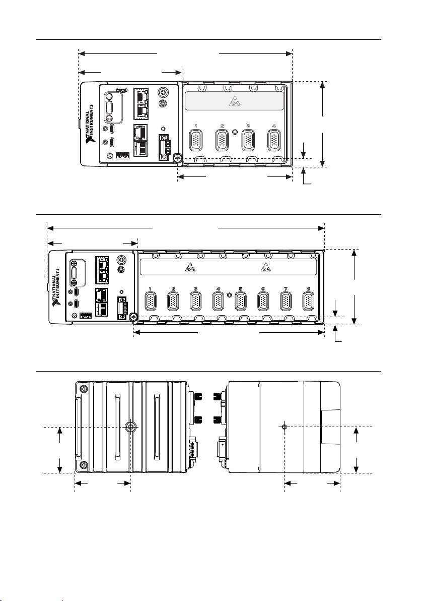
Figure 15. cRIO-904x 4-slot Controller Front Dimensions
107.0 mm (4.21 in.)
219.5 mm (8.64 in.)
117.2 mm (4.61 in.)
8.6 mm
(0.34 in.)
88.1 mm
(3.47 in.)
107.0 mm (4.21 in.)
226.6 mm (8.92 in.)
8.6 mm
(0.34 in.)
88.1 mm
(3.47 in.)
328.8 mm (12.95 in.)
44.0 mm
(1.73 in.)
44.0 mm
(1.73 in.)
44.0 mm
(1.73 in.)
44.0 mm
(1.73 in.)
53.4 mm
(2.10 in.)
53.4 mm
(2.10 in.)
53.4 mm
(2.10 in.)
53.4 mm
(2.10 in.)
Figure 16. cRIO-904x 8-slot Controller Front Dimensions
Mounting on a Flat Surface
For environments with high shock and vibration, NI recommends mounting the cRIO-904x
directly on a flat, rigid surface using the mounting holes in the cRIO-904x.
Figure 17. cRIO-904x Side Dimensions
cRIO-904x User Manual | © National Instruments | 29
Page 30
What to Use
1
2
3
• cRIO-904x
• M4 screws, user provided, which must not exceed 8 mm of insertion into the cRIO-904x
– x4 for 4-slot models
– x6 for 8-slot models
Figure 18. Mounting the 4-slot cRIO-904x Directly on a Flat Surface
30 | ni.com | cRIO-904x User Manual
Page 31

Figure 19. Mounting the 8-slot cRIO-904x Directly on a Flat Surface
1
2
3
1. Prepare the surface for mounting the cRIO-904x using the Surface Mounting
Dimensions .
2. Align the cRIO-904x on the surface.
3. Fasten the cRIO-904x to the surface using the M4 screws appropriate for the surface.
Screws must not exceed 8 mm of insertion into the cRIO-904x. Tighten the screws to a
maximum torque of 1.3 N · m (11.5 lb · in.).
Surface Mounting Dimensions
The following figures show the surface mounting dimensions for the 4-slot and 8-slot
cRIO-904x models.
cRIO-904x User Manual | © National Instruments | 31
Page 32

Figure 20. 4-slot cRIO-904x Surface Mounting Dimensions
2×
23.7 mm (0.94 in.)
2×
20.3 mm (0.80 in.)
2×
20.3 mm (0.80 in.)
6× ISO M4 × 0.7 Thread
8 mm Maximum Insertion Depth
116.5 mm (4.59 in.)
29.0 mm (1.14 in.)
3×
23.7 mm (0.94 in.)
3×
20.3 mm (0.80 in.)
3×
20.3 mm (0.80 in.)
120 mm (4.72 in.)
9× ISO M4 × 0.7 Thread
8 mm Maximum Insertion Depth
120 mm (4.72 in.)
14.8 mm (0.59 in.)
Figure 21. 8-slot cRIO-904x Surface Mounting Dimensions
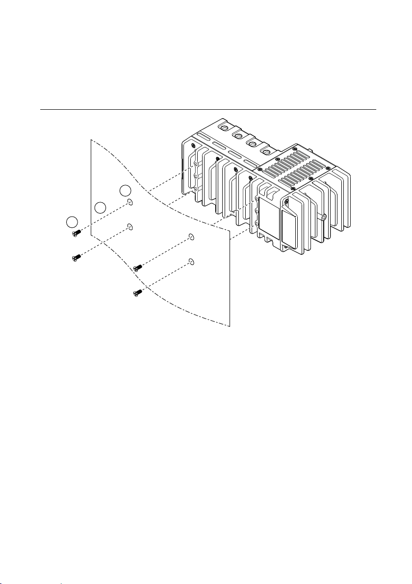
Mounting on a Panel
You can use the NI panel mounting kit to mount the cRIO-904x on a panel.
What to use
• cRIO-904x
• Screwdriver, Phillips #2
• NI panel mounting kit
– 4-slot models - 157253-01
• Panel mounting plate
• M4 x 10 screws (x4)
– 8-slot models - 157267-01
• Panel mounting plate
• M4 x 10 screws (x6)
32 | ni.com | cRIO-904x User Manual
Page 33

Figure 22. Mounting the 4-slot cRIO-904x on a Panel
1
3
2
1
2
Figure 23. Mounting the 8-slot cRIO-904x on a Panel
1. Align the cRIO-904x and the panel mounting plate.
2. Fasten the panel mounting plate to the cRIO-904x using the screwdriver and M4 x 10
screws. Tighten the screws to a maximum torque of 1.3 N · m (11.5 lb · in.).
You must use the screws provided with the NI panel mounting kit because they are the
correct depth and thread for the panel mounting plate.
cRIO-904x User Manual | © National Instruments | 33
Page 34

3. Fasten the panel mounting plate to the surface using the screwdriver and screws that are
108.8 mm (4.26 in.)
217.7 mm (8.57 in.)
199.4 mm (7.85 in.)
1.6 mm (0.06 in.)
11.1 mm (0.44 in.)
138.9 mm
(5.47 in.)
114.3 mm
(4.50 in.)
7.2 mm
(0.29 in.)
25.4 mm
(1.00 in.)
89.9 mm (3.54 in.)
147.3 mm (5.80 in.)
327 mm (12.88 in.)
152.4 mm (6.00 in.)
1.6 mm (0.06 in.)
11.1 mm (0.44 in.)
152.4 mm (6.00 in.)
138.9 mm
(5.47 in.)
114.3 mm
(4.50 in.)
7.2 mm
(0.29 in.)
25.4 mm
(1.00 in.)
appropriate for the surface. The maximum screw size is M5 or number 10.
Panel Mounting Dimensions
The following figures show the panel mounting dimensions for the 4-slot and 8-slot
cRIO-904x models.
Figure 24. 4-slot cRIO-904x Panel Mounting Dimensions
Figure 25. 8-slot cRIO-904x Panel Mounting Dimensions
Mounting on a DIN Rail
You can use the NI DIN rail mounting kit to mount the cRIO-904x on a standard 35-mm DIN
rail.
34 | ni.com | cRIO-904x User Manual
Page 35

What to use
1
2
• cRIO-904x
• Screwdriver, Phillips #2
• NI DIN rail mounting kit
– 4-slot models - 157254-01
• DIN rail clip
• M4 x 10 screws (x2)
– 8-slot models - 157268-01
• DIN rail clip
• M4 x 10 screws (x3)
Figure 26. Mounting the 4-slot cRIO-904x on a DIN Rail
cRIO-904x User Manual | © National Instruments | 35
Page 36

Figure 27. Mounting the 8-slot cRIO-904x on a DIN Rail
1
2
1
2
1. Align the cRIO-904x and the DIN rail clip.
2. Fasten the DIN rail clip to the cRIO-904x using the screwdriver and M4 x 10 screws.
Tighten the screws to a maximum torque of 1.3 N · m (11.5 lb · in.).
You must use the screws provided with the NI DIN rail kit because they are the correct
depth and thread for the DIN rail clip.
Clipping the Controller on a DIN Rail
Complete the following steps to clip the controller on a DIN rail.
Figure 28. Clipping the Controller on a DIN Rail
1. Insert one edge of the DIN rail into the deeper opening of the DIN rail clip.
2. Press down firmly to compress the spring until the clip locks in place on the DIN rail.
36 | ni.com | cRIO-904x User Manual
Notice Ensure that no C Series modules are in the controller before removing it
from the DIN rail.
Page 37

Mounting on a Rack
1
2
1
2
You can use the following rack mount kits to mount the controller and other DIN railmountable equipment on a standard 482.6 mm (19 in.) rack.
• Industrial Rack Mount Kit, 786411-01
• NI Rack-Mounting Kit, 781989-01
Note You must use the appropriate NI DIN rail mounting kit for your model in
addition to a rack-mounting kit.
Mounting on a Desktop
You can use the NI desktop mounting kit to mount the cRIO-904x on a desktop.
What to use
• cRIO-904x
• Screwdriver, Phillips #2
• NI desktop mounting kit, 779473-01
– Desktop mounting brackets (x2)
Figure 29. Mounting the 4-slot cRIO-904x on a Desktop
cRIO-904x User Manual | © National Instruments | 37
Page 38

Figure 30. Mounting the 8-slot cRIO-904x on a Desktop
1
1
2
2
1. Align the brackets with the mounting holes on the ends of the cRIO-904x.
2. Use the screwdriver to tighten the captive screws on the end of the brackets.
Desktop Mounting Dimensions
The following figures show the desktop mounting dimensions for the 4-slot and 8-slot
cRIO-904x models.
38 | ni.com | cRIO-904x User Manual
Page 39

Figure 31. 4-slot cRIO-904x Desktop Mounting Dimensions
2×
17.2 mm (0.68 in.)
39.1 mm
(1.54 in.)
253.9 mm (10.00 in.)
2×
17.2 mm (0.68 in.)
361.7 mm (14.24 in.)
39.1 mm
(1.54 in.)
Figure 32. 8-slot cRIO-904x Desktop Mounting Dimensions
cRIO-904x User Manual | © National Instruments | 39
Page 40

Figure 33. cRIO-904x Desktop Mounting Side Dimensions
132.8 mm (5.23 in.)
127.2 mm
(5.01 in.)
BIOS Configuration
Resetting the System CMOS and BIOS Settings
The cRIO-904x BIOS configuration information is stored in a nonvolatile memory location
that does not require a battery to preserve the settings. Additionally, the BIOS optimizes boot
time by saving specific system information to memory backed up by a battery (CMOS).
Complete the following steps to reset the CMOS and reset the BIOS settings to factory default
values.
1. Disconnect power from the cRIO-904x.
2. Press the CMOS reset button and hold it for 1 second.
3. Reconnect power to the cRIO-904x.
The BIOS Reset Detected warning message appears onscreen.
Note If the CMOS battery is dead, the CMOS reset button will not work.
Power-On Self Test Warning Messages
The cRIO-904x POST displays warning messages for specific issues onscreen. You can use
MAX to enable Console Out to send these warning messages through the RS-232 serial port.
The POST can display the following warning messages:
• BIOS Reset Detected—This warning is displayed when the CMOS Reset button has been
pushed. This warning indicates that the BIOS settings have the default values.
• CMOS Battery Is Dead—This warning is displayed when the CMOS battery is dead and
must be replaced. The BIOS settings are preserved even when the CMOS battery is dead,
but the system will boot very slowly because the BIOS cannot optimize boot time by
saving specific system information to CMOS.
40 | ni.com | cRIO-904x User Manual
Page 41

BIOS Setup Utility
Use the BIOS setup utility to change configuration settings and to enable special functions.
The cRIO-904x ships with configuration settings that work for most applications, but you can
use the BIOS setup utility to change configuration settings to meet the needs of your
application.
Changing BIOS settings can cause incorrect behavior, including failure to boot. In general, do
not change a setting unless you are sure what the setting does. Reset the BIOS settings to
restoring the default configuration settings.
Launching the BIOS Setup Utility
Complete the following steps to launch the BIOS setup utility.
1. Connect a video monitor to the USB 3.1 Type-C DisplayPort connector on the
cRIO-904x.
Note In order to connect the monitor to the USB 3.1 Type-C DisplayPort
connector, you may need to use a VGA-to-Type-C or DVI-to-Type-C adapter.
2. Connect a USB keyboard to the USB 2.0 host port on the cRIO-904x.
3. Power on or reboot the cRIO-904x.
4. Hold down either the <F10> key or the <Del> key until Please select boot
device: appears onscreen.
5. Use the Down Arrow key to select Enter Setup and press <Enter>. The setup utility
loads after a short delay.
The Main setup menu is displayed when you first enter the BIOS setup utility.
BIOS Setup Utility Keyboard Navigation
Use the following keys to navigate through the BIOS setup utility:
Table 17. Navigation Keys
Key(s) Function(s)
Left Arrow, Right
Arrow
Up Arrow, Down
Arrow
<Enter> Enter a submenu or display all available settings for a highlighted
<Esc> Return to the parent menu of a submenu. At the top-level menus, this
Move between the different setup menus. If you are in a submenu,
these keys have no effect, and you must press <Esc> to leave the
submenu first.
Move between the options within a setup menu.
configuration option.
key serves as a shortcut to the Exit menu.
cRIO-904x User Manual | © National Instruments | 41
Page 42

Table 17. Navigation Keys (Continued)
Key(s) Function(s)
<+>, <-> Cycle between all available settings for a selected configuration option.
<F8> Load the previous values for all BIOS configuration settings.
<F9> Load the optimal default values for all BIOS configuration settings.
The optimal default values are the same as the shipping configuration
default values.
<F10> Save settings and exits the BIOS setup utility.
Main Setup Menu
The Main setup menu reports the following configuration information:
• BIOS Version— This value indicates the version of the controller BIOS.
• Build Date—This value indicates the date and time on which the BIOS was built.
• Embedded Firmware Version—This value identifies the built-in hardware capabilities.
• Access Level— This value indicates the level of access the current user has on the
controller BIOS.
• Processor Type, Speed, and Active Processor Cores—These values indicate the type of
processor used in the controller, the speed of the processor, and the number of active
processor cores.
• Total Memory—This value indicates the size of system RAM detected by the BIOS.
The Main setup menu also includes the following settings:
• System Date—This setting controls the date, which is stored in a battery-backed real-time
clock. Most operating systems also include a way to change this setting. Use <+> and <->
in conjunction with <Enter> and <Tab> to change these values.
• System Time—This setting controls the time of day, which is stored in a battery-backed
real-time clock. Most operating systems also include a way to change this setting. Use
<+> and <-> in conjunction with <Enter> and <Tab> to change these values.
Advanced Setup Menu
The Advanced setup menu contains BIOS settings that do not require modification for normal
operation of the cRIO-904x. If you have specific problems, such as unbootable disks or
resource conflicts, you may need to examine the settings in this menu.
Notice Changing settings in the Advanced setup menu may result in an unstable or
unbootable controller. If this happens, restore BIOS settings to the factory defaults.
The Advanced setup menu includes the following submenus:
• Power/Wake Configuration Submenu
• SATA Drives Submenu
42 | ni.com | cRIO-904x User Manual
Page 43

• CPU Configuration Submenu
• USB Configuration Submenu
Power/Wake Configuration Submenu
The Power/Wake configuration submenu contains the power and wake settings for the chipset
and cRIO-904x. The factory default settings provide the most compatible and optimal
configuration.
• Ring Indicator Wake—This setting enables or disables the ability to wake a powered-off
system using the Ring Indicator pin of the RS-232 serial port. The default value is
Disabled.
• Wake on Trigger— This setting enables or disables the ability to wake a powered-off
system using a trigger programmed in software. The default value is Disabled.
SATA Drives Submenu
The SATA drives submenu contains the hard disk drive (HDD) interfaces settings. The factory
default settings provide the most compatible and optimal configuration.
• Chipset SATA—This setting enables or disables the Chipset SATA controller. The default
value is Enabled.
• Onboard Storage—This item displays the onboard drive detected in the system.
CPU Configuration Submenu
The CPU configuration submenu contains the CPU settings for the cRIO-904x. The factory
default settings provide the most compatible and optimal configuration.
CPU Power Management
The CPU Power Management submenu contains CPU power management configuration
options. The factory default settings provide the most compatible and optimal configuration.
• Burst Mode—This setting allows the processor to operate at frequencies higher than the
base processor frequency. Valid options are Enabled and Disabled. The default value is
Disabled. If enabled, the processor will run at the burst frequency if the maximum power
and temperature specifications of the processor are not exceeded. If disabled, the
processor with run at the base operating frequency. Enabling burst may increase
application jitter. As a result, NI recommends disabling burst for real time applications.
USB Configuration Submenu
The USB configuration submenu contains the USB host ports settings. The factory default
settings provide the most compatible and optimal configuration.
• Dual Role Type-C Port FW Ver— This item shows the firmware version for the dual role
USB type-C port.
• Display Port Type-C FW Ver— This items shows the firmware version for the
DisplayPort USB type-C port.
• USB Devices—This item lists the total number of devices detected in the system,
categorized by device type.
cRIO-904x User Manual | © National Instruments | 43
Page 44

• Legacy USB Support—This setting specifies whether legacy USB support is enabled.
Legacy USB support refers to the ability to use a USB keyboard and mouse during
system boot or in a legacy operating system such as DOS. Valid options are Enabled,
Disabled, and Auto. The default value is Disabled.
• Overcurrent Reporting—This setting allows the BIOS to notify the operating system
about any USB ports that source too much current. The default value is Enabled.
Hardware overcurrent protection is always active and cannot be disabled.
• USB Transfer Timeout—This setting specifies the timeout value for Control, Bulk, and
Interrupt USB transfers. The default value is 20 seconds.
• Device Reset Timeout—This setting specifies the number of seconds the POST waits for
a USB mass storage device to start. The default value is 20 seconds.
• Device Power-Up Delay—This setting specifies the maximum time a device takes before
enumerating. Valid options are Auto and Manual. The default value is Auto. When set to
Auto, a root port is granted 100 ms, and the delay value of a hub port is assigned from the
hub descriptor.
Boot Setup Menu
The Boot Setup menu contains setting related to the boot process and the boot device priority.
• Boot Settings Configuration Submenu—This item accesses the Boot Settings
Configuration submenu.
• Boot Option Priorities—These settings specify the order in which the BIOS checks for
bootable devices, including the local hard disk drive, removable devices such as USB
flash disk drives or USB CD-ROM drives, or the PXE network boot agent. The BIOS
first attempts to boot from the device associated with 1st Boot Device, followed by 2nd
Boot Device and 3rd Boot Device. If multiple boot devices are not present, the BIOS
setup utility does not display all of these configuration options. To select a boot device,
press <Enter> on the desired configuration option and select a boot device from the
resulting menu. You can also disable certain boot devices by selecting Disabled.
Note Only one device of a given type is shown in this list. If more than one
device of the same type exists, use the appropriate device BBS priorities
submenu to re-order the priority of devices of the same type.
Boot Settings Configuration Submenu
The Boot Settings Configuration submenu applies alternate configurations to boot settings.
The factory default settings provide the most compatible and optimal configuration.
• Setup Prompt Timeout—This setting specifies the number of seconds the system waits
for a BIOS Setup menu keypress (the <Delete> key). The default value is 10 seconds.
• Bootup NumLock State—This setting specifies the power-on state of the keyboard
NumLock setting. The default value is On.
44 | ni.com | cRIO-904x User Manual
Page 45

Save & Exit Menu
The Save & Exit setup menu contains all available options for exiting, saving, and loading the
BIOS default configuration. As an alternative to this menu, press <F9> to load optimal BIOS
default settings and <F10> to save changes and exit setup.
The Save & Exit setup menu includes the following settings:
• Save Changes and Reset—This setup utility then exits and reboots the cRIO-904x. Any
changes made to BIOS settings are stored in NVRAM. The <F10> key also selects this
option.
• Discard Changes and Reset—Any changes made to BIOS settings during this session of
the BIOS setup utility are discarded. The setup utility then exits and reboots the
controller. The <Esc> key can also be used to select this option.
• Save Changes—Changes made to BIOS settings during this session are committed to
NVRAM. The setup utility remains active, allowing further changes.
• Discard Changes—Any changes made to BIOS settings during this session of the BIOS
setup utility are discarded. The BIOS setup continues to be active.
• Restore Defaults—This option restores all BIOS settings to the factory default. This
option is useful if the controller exhibits unpredictable behavior due to an incorrect or
inappropriate BIOS setting. Notice that any nondefault settings such as boot order,
passwords, and so on are also restored to their factory defaults. The <F9> key also selects
this option.
• Save As User Defaults—This option saves a copy of the current BIOS settings as the
User Defaults. This option is useful for preserving custom BIOS setup configurations.
• Restore User Defaults—This option restores all BIOS settings to the user defaults. This
option is useful for restoring previously preserved custom BIOS setup configurations.
• Boot Override—This option lists all possible bootable devices and allows the user to
override the Boot Option Priorities list for the current boot. If no changes have been made
to the BIOS setup options, the system will continue booting to the selected device without
first rebooting. If BIOS setup options have been changed and saved, a reboot will be
required and the boot override selection will not be valid.
cRIO-904x User Manual | © National Instruments | 45
Page 46

Choosing Your Programming Mode
The cRIO-904x supports three programming modes. The programming modes are set per slot
on a chassis.
Real-Time Enables you to use C Series modules directly from LabVIEW Real-
Time, using NI DAQmx.
C Series modules appear under the Real-Time Resources item in the
MAX Project Explorer window and I/O channels appear as I/O
variables under the modules. To use I/O variables, you drag and drop
them from the Project Explorer window to LabVIEW Real-Time VIs.
Use this mode to make the C Series module behave like it is in a
CompactDAQ controller, using the Real-Time NI-DAQmx and NIXNET drivers to communicate, and access the four counter/timers and
the PFI trigger connector on the controller.
Real-Time
Scan (IO
Variables)
Enables you to use C Series modules directly from LabVIEW RealTime, using I/O variables.
C Series modules that you use in Scan Interface mode appear under
the Real-Time Scan Resources item in the MAX Project Explorer
window and I/O channels appear as I/O variables under the modules.
To use I/O variables, you drag and drop them from the Project
Explorer window to LabVIEW Real-Time VIs.
In this mode, you do not need to do any LabVIEW FPGA
development. LabVIEW programs the FPGA for you with a fixed
FPGA bitfile that communicates with all the C Series modules that RT
Scan mode supports. LabVIEW also sends C Series data to the RealTime host to be displayed in I/O variables. Real-Time Scan mode also
enables you to dynamically detect which types of C Series modules
are plugged into chassis slots.
46 | ni.com | cRIO-904x User Manual
Page 47

LabVIEW
FPGA
Enables you to use C Series modules from LabVIEW FPGA VIs.
C Series modules appear directly under the FPGA Target item in the
MAX Project Explorer window and I/O channels appear as FPGA I/O
items under the FPGA Target. To access the I/O channels, you either
configure FPGA I/O Nodes in a LabVIEW FPGA VI or drag and drop
the I/O channels from the Project Explorer window to a LabVIEW
FPGA VI block diagram.
Use this mode to add more flexibility, customization, timing, and
synchronization to your applications. To use the CompactRIO system
in FPGA mode, you must either have the LabVIEW FPGA Module
installed on the host computer, or have access to a compiled bitfile
that you can download to the FPGA. In either case, you use the Open
FPGA VI Reference function in a LabVIEW Real-Time VI to access
the FPGA VI or bitfile.
Use the following table to assist you in choosing a supported programming mode for your
task.
Table 18. Supported Programming Modes for Popular Tasks
Task Real-Time Real-Time Scan (IO
Variables)
LabVIEW FPGA
Control rates up to 1 kHz ■ ■
Control rates between 1 kHz and
■ ■
5 kHz (application dependent)
Control rates over 5 kHz ■
High-speed waveform acquisition ■ ■
Note Some C Series modules can only be used in certain programming modes. For
module-specific software support information, visit ni.com/info and enter the Info
Code swsupport.
To learn more about using the cRIO-904x in Real-Time mode, refer to the following sections:
• Analog Input with NI-DAQmx
• Analog Output with NI-DAQmx
• Digital Input/Output with NI-DAQmx
• PFI with NI-DAQmx
• Counters with NI-DAQmx
Analog Input with NI-DAQmx
To perform analog input measurements, install a supported analog input C Series module into
any slot on the cRIO controller and set the programming mode to Real-Time (NI-DAQmx)
mode. The measurement specifications, such as number of channels, channel configuration,
sample rate, and gain, are determined by the type of C Series module used. For more
cRIO-904x User Manual | © National Instruments | 47
Page 48

information and wiring diagrams, refer to the documentation included with your C Series
modules.
The cRIO controller has eight input timing engines, which means that up to eight hardwaretimed analog input tasks can be running at a time on the controller. An analog input task can
include channels from multiple analog input modules. However, channels from a single
module cannot be used in multiple tasks.
Multiple timing engines allow the cRIO controller to run up to eight analog input tasks
simultaneously, each using independent timing and triggering configurations. The eight timing
engines are it0, it1,…it7.
Analog Input Triggering Signal
A trigger is a signal that causes an action, such as starting or stopping the acquisition of data.
When you configure a trigger, you must decide how you want to produce the trigger and the
action you want the trigger to cause. The cRIO controller supports internal software triggering,
external digital triggering, analog triggering, and internal time triggering.
Three triggers are available: Start Trigger, Reference Trigger, and Pause Trigger. An analog or
digital signal can initiate these three trigger actions. C Series Parallel digital input modules and
the controller’s integrated PFI trigger line can be used in any controller slot to supply a digital
trigger. To find your module triggering options, refer to the documentation included with your
C Series modules. For more information about using digital modules for triggering, refer to the
Digital Input/Output with NI-DAQmx section.
Refer to the AI Start Trigger Signal, AI Reference Trigger Signal, and AI Pause Trigger Signal
sections for more information about the analog input trigger signals.
Hardware-Timed Single Point (HWTSP) Mode
In HWTSP mode, samples are acquired or generated continuously using hardware timing and
no buffer. You must use the sample clock or change detection timing types. No other timing
types are supported.
Use HWTSP mode if you need to know if a loop executes in a given amount of time, such as
in a control application. Because there is no buffer, if you use HWTSP mode, ensure that reads
or writes execute fast enough to keep up with hardware timing. If a read or write executes late,
it returns a warning.
Note DSA modules do not support HWTSP mode.
Analog Input Timing Signals
The cRIO controller features the following analog input timing signals:
• AI Sample Clock Signal*
• AI Sample Clock Timebase Signal
• AI Start Trigger Signal*
48 | ni.com | cRIO-904x User Manual
Page 49

• AI Reference Trigger Signal*
Programmable
Clock
Divider
Sample Clock
Timebase
PFI
Analog Comparison Event
Ctr n Internal Output
AI Sample
Clock
Sigma-Delta Module Internal Output
Analog Comparison
Event
80 MHz Timebase
20 MHz Timebase
PFI
13.1072 MHz Timebase
12.8 MHz Timebase
10 MHz Timebase
100 kHz Timebase
• AI Pause Trigger Signal*
Signals with an * support digital filtering. Refer to the PFI Filters section for more
information.
Refer to the AI Convert Clock Signal Behavior For Analog Input Modules section for more
information about AI Convert Clock signals and the cRIO controller.
AI Sample Clock Signal
A sample consists of one reading from each channel in the AI task. Sample Clock signals the
start of a sample of all analog input channels in the task. The sample clock can be generated
from external or internal sources as shown in the figure below.
Figure 34. AI Sample Clock Timing Options
Routing the Sample Clock to an Output Terminal
You can route Sample Clock to any output PFI terminal. Sample Clock is an active high pulse
by default.
AI Sample Clock Timebase Signal
The AI Sample Clock Timebase signal is divided down to provide a source for Sample Clock.
AI Sample Clock Timebase can be generated from external or internal sources. AI Sample
Clock Timebase is not available as an output from the controller.
cRIO-904x User Manual | © National Instruments | 49
Page 50

AI Start Trigger Signal
Use the Start Trigger signal to begin a measurement acquisition which consists of one or more
samples. Once the acquisition begins, configure the acquisition to stop in one of the following
ways:
• When a certain number of points has been sampled (in finite mode)
• After a hardware reference trigger (in finite mode)
• With a software command (in continuous mode)
An acquisition that uses a start trigger (but not a reference trigger) is sometimes referred to as
a posttriggered acquisition. That is, samples are measured only after the trigger.
When you are using an internal sample clock, you can specify a default delay from the start
trigger to the first sample.
Using a Digital Source
To use the Start Trigger signal with a digital source, specify a source and a rising or falling
edge. Use the following signals as the source:
• Any PFI terminal
• Counter n Internal Output
The source also can be one of several other internal signals on your cRIO controller. Refer to
the "Device Routing in MAX" topic in the NI-DAQmx Help or the LabVIEW Help for more
information.
Using an Analog Source
Some C Series modules can generate a trigger based on an analog signal. In NI-DAQmx, this
is called the Analog Comparison Event. When you use an analog trigger source for Start
Trigger, the acquisition begins on the first rising edge of the Analog Comparison Event signal.
Routing AI Start Trigger to an Output Terminal
You can route the Start Trigger signal to any output PFI terminal. The output is an active high
pulse.
Using a Time Source
To use the Start Trigger signal with a time source, configure a specific time in NI-DAQmx.
Refer to the "Timestamps" and "Time Triggering" topics in the NI-DAQmx Help for more
information on accessing time-based features in the NI-DAQmx API.
AI Reference Trigger Signal
Use a reference trigger to stop a measurement acquisition. To use a reference trigger, specify a
buffer of finite size and a number of pretrigger samples (samples that occur before the
reference trigger). The number of posttrigger samples (samples that occur after the reference
trigger) desired is the buffer size minus the number of pretrigger samples.
50 | ni.com | cRIO-904x User Manual
Page 51

Once the acquisition begins, the cRIO controller writes samples to the buffer. After the cRIO
Reference Trigger
Pretrigger Samples
Complete Buffer
Posttrigger Samples
controller captures the specified number of pretrigger samples, the cRIO controller begins to
look for the reference trigger condition. If the reference trigger condition occurs before the
cRIO controller captures the specified number of pretrigger samples, the controller ignores the
condition.
If the buffer becomes full, the cRIO controller continuously discards the oldest samples in the
buffer to make space for the next sample. This data can be accessed (with some limitations)
before the cRIO controller discards it. Refer to the Can a Pretriggered Acquisition be
Continuous? document for more information. To access this document, go to ni.com/info and
enter the Info Code rdcanq.
When the reference trigger occurs, the cRIO controller continues to write samples to the buffer
until the buffer contains the number of posttrigger samples desired. The figure below shows
the final buffer.
Figure 35. Reference Trigger Final Buffer
Using a Digital Source
To use a reference trigger with a digital source, specify a source and a rising or falling edge.
Either PFI or one of several internal signals on the cRIO controller can provide the source.
Refer to the "Device Routing in MAX" topic in the NI-DAQmx Help or the LabVIEW Help for
more information.
Using an Analog Source
Some C Series modules can generate a trigger based on an analog signal. In NI-DAQmx, this
is called the Analog Comparison Event.
When you use an analog trigger source, the acquisition stops on the first rising or falling edge
of the Analog Comparison Event signal, depending on the trigger properties.
Routing the Reference Trigger Signal to an Output Terminal
You can route a reference trigger to any output PFI terminal. Reference Trigger is active high
by default.
cRIO-904x User Manual | © National Instruments | 51
Page 52

AI Pause Trigger Signal
You can use the Pause Trigger to pause and resume a measurement acquisition. The internal
sample clock pauses while the external trigger signal is active and resumes when the signal is
inactive. You can program the active level of the pause trigger to be high or low.
Using a Digital Source
To use the Pause Trigger, specify a source and a polarity. The source can be either from PFI or
one of several other internal signals on your cRIO controller. Refer to the "Device Routing in
MAX" topic in the NI-DAQmx Help or the LabVIEW Help for more information.
Using an Analog Source
Some C Series modules can generate a trigger based on an analog signal. In NI-DAQmx, this
is called the Analog Comparison Event.
When you use an analog trigger source, the internal sample clock pauses when the Analog
Comparison Event signal is low and resumes when the signal goes high (or vice versa).
Note Pause triggers are only sensitive to the level of the source, not the edge.
AI Convert Clock Signal Behavior For Analog Input Modules
Refer to the Scanned Modules, Simultaneous Sample-and-Hold Modules, Delta-Sigma
Modules, and Slow Sample Rate Modules sections for information about the AI Convert Clock
signal and C Series analog input modules.
Scanned Modules
Scanned C Series analog input modules contain a single A/D converter and a multiplexer to
select between multiple input channels. When the module interface receives a Sample Clock
pulse, it begins generating a Convert Clock for each scanned module in the current task. Each
Convert Clock signals the acquisition of a single channel from that module. The Convert
Clock rate depends on the module being used, the number of channels used on that module,
and the system Sample Clock rate.
The driver chooses the fastest conversion rate possible based on the speed of the A/D
converter for each module and adds 10 µs of padding between each channel to allow for
adequate settling time. This scheme enables the channels to approximate simultaneous
sampling. If the AI Sample Clock rate is too fast to allow for 10 µs of padding, NI-DAQmx
selects a conversion rate that spaces the AI Convert Clock pulses evenly throughout the
sample. NI-DAQmx uses the same amount of padding for all the modules in the task. To
explicitly specify the conversion rate, use the ActiveDevs and AI Convert Clock Rate
properties using the DAQmx Timing property node or functions.
52 | ni.com | cRIO-904x User Manual
Page 53

Simultaneous Sample-and-Hold Modules
Simultaneous sample-and-hold (SSH) C Series analog input modules contain multiple A/D
converters or circuitry that allows all the input channels to be sampled at the same time. These
modules sample their inputs on every Sample Clock pulse.
Delta-Sigma Modules
Delta-sigma C Series analog input modules function much like SSH modules, but use A/D
converters that require a high-frequency oversample clock to produce accurate, synchronized
data. Some delta-sigma modules in the cRIO controller automatically share a single
oversample clock to synchronize data from all the modules that support an external
oversample clock timebase when they all share the same task. (DSA modules are an example).
The oversample clock is used as the AI Sample Clock Timebase. The cRIO controller supplies
10 MHz, 12.8 MHz, and 13.1072 MHz timebases from which software automatically selects
based on the modules in the task. When delta-sigma modules with different oversample clock
frequencies are used in an analog input task, the AI Sample Clock Timebase can use any of the
available frequencies; by default, the fastest available is used. The sample rate of all modules
in the task is an integer divisor of the frequency of the AI Sample Clock Timebase.
When one or more delta-sigma modules are in an analog input task, the delta-sigma modules
also provide the signal used as the AI Sample Clock. This signal is used to cause A/D
conversion for other modules in the system, just as the AI Sample Clock does when a deltasigma module is not being used.
When delta-sigma modules are in an AI task, the controller automatically issues a
synchronization pulse to each delta-sigma module so that their ADCs are reset at the same
time. Because of the filtering used in delta-sigma A/D converters, these modules usually
exhibit a fixed input delay relative to non-delta-sigma modules in the system. This input delay
is specified in the C Series module documentation.
When channels from delta-sigma C Series modules are included in a multi-chassis task, please
ensure that the first channel in your channel list is from a delta-sigma module.
Note DSA modules do not support HWTSP mode.
Slow Sample Rate Modules
Some C Series analog input modules are specifically designed for measuring signals that vary
slowly, such as temperature. Because of their slow rate, it is not appropriate for these modules
to constrain the AI Sample Clock to operate at or slower than their maximum rate. When using
such a module in the cRIO controller mixed with a non-slow sample module in the same task,
exceeding the maximum sampling rate of the slow sample module results in the most recently
acquired sample being read multiple times. In this scenario, the first sample of a hardwaretimed acquisition with a slow sampled C Series module is sampled when the task is
committed.
cRIO-904x User Manual | © National Instruments | 53
Page 54

For more information about which C Series modules are compatible with the cRIO controller,
go to ni.com/info and enter the Info Code rdcdaq.
Getting Started with AI Applications in Software
You can use the cRIO controller in the following analog input applications:
• Single-point acquisition
• Hardware-Timed Single Point acquisition
• Finite acquisition
• Continuous acquisition
For more information about programming analog input applications and triggers in software,
refer to the NI-DAQmx Help or the LabVIEW Help for more information.
Analog Output with NI-DAQmx
To generate analog output, install an analog output C Series module in any slot on the cRIO
controller. The generation specifications, such as the number of channels, channel
configuration, update rate, and output range, are determined by the type of C Series module
used. For more information, refer to the documentation included with your C Series module(s).
The cRIO controller has eight output timing engines, which means that up to eight hardwaretimed analog output tasks can be running at a time on the controller. On a single analog output
C Series module, you can assign any number of channels to either a hardware-timed task or a
software-timed (single-point) task. However, you cannot assign some channels to a hardwaretimed task and other channels (on the same module) to a software-timed task.
Multiple timing engines allow the cRIO controller to run up to eight analog output tasks
simultaneously, each using independent timing and triggering configurations. The eight timing
engines are ot0, ot1,… ot7.
Analog Output Data Generation Methods
When performing an analog output operation, you either can perform software-timed
generations or hardware-timed generations.
Software-Timed Generations
With a software-timed generation, software controls the rate at which data is generated.
Software sends a separate command to the hardware to initiate each DAC conversion. In NIDAQmx, software-timed generations are referred to as on-demand timing. Software-timed
generations are also referred to as immediate or static operations. They are typically used for
writing out a single value, such as a constant DC voltage.
The following considerations apply to software-timed generations:
• If any AO channel on a module is used in a hardware-timed (waveform) task, no channels
on that module can be used in a software-timed task
• You can configure software-timed generations to simultaneously update
54 | ni.com | cRIO-904x User Manual
Page 55

• Only one simultaneous update task can run at a time
• A hardware-timed AO task and a simultaneous update AO task cannot run at the same
time
Hardware-Timed Generations
With a hardware-timed generation, a digital hardware signal controls the rate of the generation.
This signal can be generated internally on the controller or provided externally.
Hardware-timed generations have several advantages over software-timed acquisitions:
• The time between samples can be much shorter
• The timing between samples is deterministic
• Hardware-timed acquisitions can use hardware triggering
Hardware-Timed Single Point (HWTSP) Mode
In HWTSP mode, samples are acquired or generated continuously using hardware timing and
no buffer. You must use the sample clock or change detection timing types. No other timing
types are supported.
Use HWTSP mode if you need to know if a loop executes in a given amount of time, such as
in a control application. Because there is no buffer, if you use HWTSP mode, ensure that reads
or writes execute fast enough to keep up with hardware timing. If a read or write executes late,
it returns a warning.
Note DSA modules do not support HWTSP mode.
Buffered Analog Input
A buffer is a temporary storage in computer memory for generated samples. In a buffered
generation, data is moved from a host buffer to the cRIO controller onboard FIFO before it is
written to the C Series modules.
One property of buffered I/O operations is sample mode. The sample mode can be either finite
or continuous:
• Finite—Finite sample mode generation refers to the generation of a specific,
predetermined number of data samples. After the specified number of samples is written
out, the generation stops.
• Continuous—Continuous generation refers to the generation of an unspecified number of
samples. Instead of generating a set number of data samples and stopping, a continuous
generation continues until you stop the operation. There are three different continuous
generation modes that control how the data is written. These modes are regeneration,
onboard regeneration, and non-regeneration:
– In regeneration mode, you define a buffer in host memory. The data from the buffer
is continually downloaded to the FIFO to be written out. New data can be written to
cRIO-904x User Manual | © National Instruments | 55
Page 56

the host buffer at any time without disrupting the output. There is no limitation on
the number of waveform channels supported by regeneration mode.
– With onboard regeneration, the entire buffer is downloaded to the FIFO and
regenerated from there. After the data is downloaded, new data cannot be written to
the FIFO. To use onboard regeneration, the entire buffer must fit within the FIFO
size. The advantage of using onboard regeneration is that it does not require
communication with the main host memory once the operation is started, which
prevents problems that may occur due to excessive bus traffic or operating system
latency. There is a limit of 16 waveform channels for onboard regeneration.
– With non-regeneration, old data is not repeated. New data must continually be
written to the buffer. If the program does not write new data to the buffer at a fast
enough rate to keep up with the generation, the buffer underflows and causes an
error. There is no limitation on the number of waveform channels supported by nonregeneration.
Analog Output Triggering Signals
A trigger is a signal that causes an action, such as starting or stopping the acquisition of data.
When you configure a trigger, you must decide how you want to produce the trigger and the
action you want the trigger to cause. The cRIO controller supports internal software triggering,
external digital triggering, analog triggering, and internal time triggering.
Analog output supports two different triggering actions: AO Start Trigger and AO Pause
Trigger. An analog or digital signal can initiate these actions. C Series parallel digital input
modules and the controller’s integrated PFI trigger line can be used in any controller slot to
supply a digital trigger. An analog trigger can be supplied by some C Series analog modules.
Refer to the AO Start Trigger Signal and AO Pause Trigger Signal sections for more
information about the analog output trigger signals.
Analog Output Timing Signals
The cRIO controller features the following AO (waveform generation) timing signals:
• AO Sample Clock Signal*
• AO Sample Clock Timebase Signal
• AO Start Trigger Signal*
• AO Pause Trigger Signal*
Signals with an * support digital filtering. Refer to the PFI Filters section for more
information.
AO Sample Clock Signal
The AO sample clock signals when all the analog output channels in the task update. AO
Sample Clock can be generated from external or internal sources as shown in the figure below.
56 | ni.com | cRIO-904x User Manual
Page 57

Figure 36. Analog Output Timing Options
Programmable
Clock
Divider
AO Sample Clock
Timebase
PFI
Analog Comparison Event
Ctr n Internal Output
Sample
Clock
Analog Comparison
Event
80 MHz Timebase
20 MHz Timebase
PFI
13.1072 MHz Timebase
12.8 MHz Timebase
10 MHz Timebase
100 kHz Timebase
Routing AO Sample Clock to an Output Terminal
You can route AO Sample Clock to any output PFI terminal. AO Sample Clock is active high
by default.
AO Sample Clock Timebase Signal
The AO Sample Clock Timebase signal is divided down to provide a source for AO Sample
Clock. AO Sample Clock Timebase can be generated from external or internal sources, and is
not available as an output from the controller.
Delta-Sigma Modules
The oversample clock is used as the AO Sample Clock Timebase. The cRIO controller
supplies 10 MHz, 12.8 MHz, and 13.1072 MHz timebases. When delta-sigma modules with
different oversample clock frequencies are used in an analog output task, the AO Sample
Clock Timebase can use any of the available frequencies; by default, the fastest available is
used. The update rate of all modules in the task is an integer divisor of the frequency of the
AO Sample Clock Timebase.
AO Start Trigger Signal
Use the AO Start Trigger signal to initiate a waveform generation. If you do not use triggers,
you can begin a generation with a software command. If you are using an internal sample
clock, you can specify a delay from the start trigger to the first sample. For more information,
refer to the NI-DAQmx Help.
Note DSA modules do not support HWTSP mode.
cRIO-904x User Manual | © National Instruments | 57
Page 58

Using a Digital Source
Pause Trigger
Sample Clock
To use AO Start Trigger, specify a source and a rising or falling edge. The source can be one
of the following signals:
• A pulse initiated by host software
• Any PFI terminal
• AI Reference Trigger
• AI Start Trigger
The source also can be one of several internal signals on the cRIO controller. Refer to the
"Device Routing in MAX" topic in the NI-DAQmx Help or the LabVIEW Help for more
information.
You also can specify whether the waveform generation begins on the rising edge or falling
edge of AO Start Trigger.
Routing AO Start Trigger Signal to an Output Terminal
You can route AO Start Trigger to any output PFI terminal. The output is an active high pulse.
Using a Time Source
To use the Start Trigger signal with a time source, configure a specific time in NI-DAQmx.
Refer to the "Timestamps" and "Time Triggering" topics in the NI-DAQmx Help for more
information on accessing time-based features in the NI-DAQmx API.
AO Pause Trigger Signal
Use the AO Pause Trigger signal to mask off samples in a DAQ sequence. When AO Pause
Trigger is active, no samples occur, but AO Pause Trigger does not stop a sample that is in
progress. The pause does not take effect until the beginning of the next sample.
When you generate analog output signals, the generation pauses as soon as the pause trigger is
asserted. If the source of the sample clock is the onboard clock, the generation resumes as soon
as the pause trigger is deasserted, as shown in the following figure.
Figure 37. AO Pause Trigger with the Onboard Clock Source
If you are using any signal other than the onboard clock as the source of the sample clock, the
generation resumes as soon as the pause trigger is deasserted and another edge of the sample
clock is received, as shown in the following figure.
58 | ni.com | cRIO-904x User Manual
Page 59

Figure 38. AO Pause Trigger with Other Signal Source
Pause Trigger
Sample Clock
Using a Digital Source
To use AO Pause Trigger, specify a source and a polarity. The source can be a PFI signal or
one of several other internal signals on the cRIO controller.
You also can specify whether the samples are paused when AO Pause Trigger is at a logic high
or low level. Refer to the "Device Routing in MAX" topic in the NI-DAQmx Help or the
LabVIEW Help for more information.
Minimizing Glitches on the Output Signal
When you use a DAC to generate a waveform, you may observe glitches on the output signal.
These glitches are normal; when a DAC switches from one voltage to another, it produces
glitches due to released charges. The largest glitches occur when the most significant bit of the
DAC code changes. You can build a lowpass deglitching filter to remove some of these
glitches, depending on the frequency and nature of the output signal. Go to ni.com/support for
more information about minimizing glitches.
Getting Started with AO Applications in Software
You can use the cRIO controller in the following analog output applications:
• Single-point (on-demand) generation
• Hardware-Timed Single Point generation
• Finite generation
• Continuous generation
• Waveform generation
For more information about programming analog output applications and triggers in software,
refer to NI-DAQmx Help or to the LabVIEW Help.
Digital Input/Output with NI-DAQmx
To use digital I/O, install a digital C Series module into any slot on the cRIO controller. The
I/O specifications, such as number of lines, logic levels, update rate, and line direction, are
determined by the type of C Series module used. For more information, refer to the
documentation included with your C Series module(s).
cRIO-904x User Manual | © National Instruments | 59
Page 60

Serial DIO versus Parallel DIO Modules
Serial digital modules have more than eight lines of digital input/output. They can be used in
any controller slot and can perform the following tasks:
• Software-timed and hardware-timed digital input/output tasks
Parallel digital modules can be used in any controller slot and can perform the following tasks:
• Software-timed and hardware-timed digital input/output tasks
• Counter/timer tasks (can be used in up to two slots)
• Accessing PFI signal tasks (can be used in up to two slots)
• Filter digital input signals
Software-timed and hardware-timed digital input/output tasks have the following restrictions:
• You cannot use parallel and serial modules together on the same hardware-timed task.
• You cannot use serial modules for triggering.
• You cannot do both static and timed tasks at the same time on a single serial module.
• You can only do hardware timing in one direction at a time on a serial bidirectional
module.
To determine the capability of digital modules supported by the controller, refer to the
Software Support for CompactRIO, CompactDAQ, Single-Board RIO, R Series, and EtherCAT
document by going to ni.com/info and entering the Info Code rdcdaq.
Static DIO
Each of the DIO lines can be used as a static DI or DO line. You can use static DIO lines to
monitor or control digital signals on some C Series modules. Each DIO line can be
individually configured as a digital input (DI) or digital output (DO), if the C Series module
being used allows such configuration.
All samples of static DI lines and updates of static DO lines are software-timed.
Digital Input
You can acquire digital waveforms using either parallel or serial digital modules. The DI
waveform acquisition FIFO stores the digital samples. The cRIO controller samples the DIO
lines on each rising or falling edge of the DI Sample Clock signal.
Multiple input timing engines allow the cRIO controller to run up to eight hardware-timed
digital input tasks simultaneously, each using independent timing and triggering
configurations. The eight input timing engines are it0, it1,…it7. All eight of the input timing
engines are shared between analog input and digital input tasks, allowing up to 8 hardwaretimed input tasks.
60 | ni.com | cRIO-904x User Manual
Page 61

Hardware-Timed Single Point (HWTSP) Mode
In HWTSP mode, samples are acquired or generated continuously using hardware timing and
no buffer. You must use the sample clock or change detection timing types. No other timing
types are supported.
Use HWTSP mode if you need to know if a loop executes in a given amount of time, such as
in a control application. Because there is no buffer, if you use HWTSP mode, ensure that reads
or writes execute fast enough to keep up with hardware timing. If a read or write executes late,
it returns a warning.
Note DSA modules do not support HWTSP mode.
Digital Input Triggering Signals
A trigger is a signal that causes an action, such as starting or stopping the acquisition of data.
When you configure a trigger, you must decide how you want to produce the trigger and the
action you want the trigger to cause. The cRIO controller supports internal software triggering,
external digital triggering, analog triggering, and internal time triggering.
Three triggers are available: Start Trigger, Reference Trigger, and Pause Trigger. An analog or
digital trigger can initiate these three trigger actions. C Series parallel digital input modules
and the controller’s integrated PFI trigger line can be used in any controller slot to supply a
digital trigger. To find your module triggering options, refer to the documentation included
with your C Series modules. For more information about using analog modules for triggering,
refer to the Analog Input Triggering Signal and Analog Output Triggering Signals sections.
Refer to the DI Start Trigger Signal, DI Reference Trigger Signal, and DI Pause Trigger
Signal sections in Digital Input Timing Signals for more information about the digital input
trigger signals.
Digital Input Timing Signals
The cRIO controller features the following digital input timing signals:
• DI Sample Clock Signal*
• DI Sample Clock Timebase Signal
• DI Start Trigger Signal*
• DI Reference Trigger Signal*
• DI Pause Trigger Signal*
Signals with an * support digital filtering. Refer to the PFI Filters section for more
information.
DI Sample Clock Signal
Use the DI Sample Clock signal to sample digital I/O on any slot using parallel digital
modules, and store the result in the DI waveform acquisition FIFO. If the cRIO controller
cRIO-904x User Manual | © National Instruments | 61
Page 62

receives a DI Sample Clock signal when the FIFO is full, it reports an overflow error to the
Programmable
Clock
Divider
DI Sample Clock
Timebase
PFI
Analog Comparison Event
Ctr n Internal Output
Sample
Clock
Sigma-Delta Module Internal Output
Analog Comparison
Event
80 MHz Timebase
20 MHz Timebase
PFI
13.1072 MHz Timebase
12.8 MHz Timebase
10 MHz Timebase
100 kHz Timebase
host software.
A sample consists of one reading from each channel in the DI task. DI Sample Clock signals
the start of a sample of all digital input channels in the task. DI Sample Clock can be generated
from external or internal sources as shown in the following figure.
Figure 39. DI Sample Clock Timing Options
Routing DI Sample Clock to an Output Terminal
You can route DI Sample Clock to any output PFI terminal.
DI Sample Clock Timebase Signal
The DI Sample Clock Timebase signal is divided down to provide a source for DI Sample
Clock. DI Sample Clock Timebase can be generated from external or internal sources. DI
Sample Clock Timebase is not available as an output from the controller.
Using an Internal Source
To use DI Sample Clock with an internal source, specify the signal source and the polarity of
the signal. Use the following signals as the source:
• it Sample Clock
• ot Sample Clock
• Counter n Internal Output
• Frequency Output
• DI Change Detection Output
Several other internal signals can be routed to DI Sample Clock. Refer to the "Device Routing
in MAX" topic in the NI-DAQmx Help or the LabVIEW Help for more information.
62 | ni.com | cRIO-904x User Manual
Page 63

Using an External Source
You can route the following signals as DI Sample Clock:
• Any PFI terminal
• Analog Comparison Event (an analog trigger)
You can sample data on the rising or falling edge of DI Sample Clock.
Routing DI Sample Clock to an Output Terminal
You can route DI Sample Clock to any output PFI terminal. The PFI circuitry inverts the
polarity of DI Sample Clock before driving the PFI terminal.
DI Start Trigger Signal
Use the DI Start Trigger signal to begin a measurement acquisition. A measurement
acquisition consists of one or more samples. If you do not use triggers, begin a measurement
with a software command. Once the acquisition begins, configure the acquisition to stop in one
of the following ways:
• When a certain number of points has been sampled (in finite mode)
• After a hardware reference trigger (in finite mode)
• With a software command (in continuous mode)
An acquisition that uses a start trigger (but not a reference trigger) is sometimes referred to as
a posttriggered acquisition. That is, samples are measured only after the trigger.
When you are using an internal sample clock, you can specify a delay from the start trigger to
the first sample.
Using a Time Source
To use the Start Trigger signal with a time source, configure a specific time in NI-DAQmx.
Refer to the "Timestamps" and "Time Triggering" topics in the NI-DAQmx Help for more
information on accessing time-based features in the NI-DAQmx API.
Using a Digital Source
To use DI Start Trigger with a digital source, specify a source and a rising or falling edge. Use
the following signals as the source:
• Any PFI terminal
• Counter n Internal Output
The source also can be one of several other internal signals on the cRIO controller. Refer to the
"Device Routing in MAX" topic in the NI-DAQmx Help or the LabVIEW Help for more
information.
Routing DI Start Trigger to an Output Terminal
You can route DI Start Trigger to any output PFI terminal. The output is an active high pulse.
cRIO-904x User Manual | © National Instruments | 63
Page 64

DI Reference Trigger Signal
Reference Trigger
Pretrigger Samples
Complete Buffer
Posttrigger Samples
Use a reference trigger signal to stop a measurement acquisition. To use a reference trigger,
specify a buffer of finite size and a number of pretrigger samples (samples that occur before
the reference trigger). The number of posttrigger samples (samples that occur after the
reference trigger) desired is the buffer size minus the number of pretrigger samples.
Once the acquisition begins, the cRIO controller writes samples to the buffer. After the cRIO
controller captures the specified number of pretrigger samples, the controller begins to look for
the reference trigger condition. If the reference trigger condition occurs before the cRIO
controller captures the specified number of pretrigger samples, the controller ignores the
condition.
If the buffer becomes full, the cRIO controller continuously discards the oldest samples in the
buffer to make space for the next sample. This data can be accessed (with some limitations)
before the cRIO controller discards it. Refer to the Can a Pretriggered Acquisition be
Continuous? document for more information. To access this document, go to ni.com/info and
enter the Info Code rdcanq.
When the reference trigger occurs, the cRIO controller continues to write samples to the buffer
until the buffer contains the number of posttrigger samples desired. The figure below shows
the final buffer.
Figure 40. Reference Trigger Final Buffer
Using a Digital Source
To use DI Reference Trigger with a digital source, specify a source and a rising or falling edge.
Either PFI or one of several internal signals on the cRIO controller can provide the source.
Refer to the "Device Routing in MAX" topic in the NI-DAQmx Help or the LabVIEW Help for
more information.
Routing DI Reference Trigger Signal to an Output Terminal
You can route DI Reference Trigger to any output PFI terminal. Reference Trigger is active
high by default.
64 | ni.com | cRIO-904x User Manual
Page 65

DI Pause Trigger Signal
Digital Input P0.x
Filter Clock
Filtered Input
1 1 21 1 21
You can use the DI Pause Trigger signal to pause and resume a measurement acquisition. The
internal sample clock pauses while the external trigger signal is active and resumes when the
signal is inactive. You can program the active level of the pause trigger to be high or low.
Using a Digital Source
To use DI Pause Trigger, specify a source and a polarity. The source can be either from PFI or
one of several other internal signals on your cRIO controller. Refer to the "Device Routing in
MAX" topic in the NI-DAQmx Help or the LabVIEW Help for more information.
Digital Input Filters
When performing a hardware timed task, you can enable a programmable debouncing filter on
the digital input lines of a parallel DIO module. All lines on a module must share the same
filter configuration. When the filter is enabled, the controller samples the inputs with a userconfigured Filter Clock derived from the controller timebase. This is used to determine
whether a pulse is propagated to the rest of the system. However, the filter also introduces
jitter onto the input signal.
In NI-DAQmx, the filter is programmed by setting the minimum pulse width, Tp2, that will
pass the filter, and is selectable in 25 ns increments. The appropriate Filter Clock is selected by
the driver. Pulses of length less than 1/2 Tp will be rejected, and the filtering behavior of
lengths between 1/2 Tp and 1 Tp are not defined because they depend on the phase of the
Filter Clock relative to the input signal.
The figure below shows an example of low-to-high transitions of the input signal. High-to-low
transitions work similarly.
Assume that an input terminal has been low for a long time. The input terminal then changes
from low to high, but glitches several times. When the filter clock has sampled the signal high
on consecutive rising edges, the low-to-high transition is propagated to the rest of the circuit.
Getting Started with DI Applications in Software
You can use the cRIO controller in the following digital input applications:
• Single-point acquisition
• Hardware-Timed Single Point acquisition
Figure 41. Filter Example
2
Tp is a nominal value; the accuracy of the controller timebase and I/O distortion will affect this
value.
cRIO-904x User Manual | © National Instruments | 65
Page 66

• Finite acquisition
• Continuous acquisition
For more information about programming digital input applications and triggers in software,
refer to the NI-DAQmx Help or the LabVIEW Help for more information.
Change Detection Event
The Change Detection Event is the signal generated when a change on the rising or falling
edge lines is detected by the change detection task.
Routing Change Detection Event to an Output Terminal
You can route ChangeDetectionEvent to any output PFI terminal.
Change Detection Acquisition
You can configure lines on parallel digital modules to detect rising or falling edges. When one
or more of these lines sees the edge specified for that line, the cRIO controller samples all the
lines in the task. The rising and falling edge lines do not necessarily have to be in the task.
Change detection acquisitions can only be buffered:
• Buffered Change Detection Acquisition—A buffer is a temporary storage in computer
memory for acquired samples. In a buffered acquisition, data is stored in the cRIO
controller onboard FIFO then transferred to a PC buffer. Buffered acquisitions typically
allow for much faster transfer rates than nonbuffered acquisitions because data
accumulates and is transferred in blocks, rather than one sample at a time.
Digital Output
To generate digital output, install a digital output C Series module in any slot on the cRIO
controller. The generation specifications, such as the number of channels, channel
configuration, update rate, and output range, are determined by the type of C Series module
used. For more information, refer to the documentation included with your C Series module(s).
With parallel digital output modules (formerly known as hardware-timed modules), you can do
multiple software-timed tasks on a single module, as well as mix hardware-timed and
software-timed digital output tasks on a single module. On serial digital output modules
(formerly known as static digital output modules), you cannot mix hardware-timed and
software-timed tasks, but you can run multiple software-timed tasks.
You may have a hardware-timed task or a software-timed task include channels from multiple
modules, but a hardware-timed task may not include a mix of channels from both parallel and
serial modules. Multiple timing engines allow the cRIO controller to run up to eight hardwaretimed digital output tasks simultaneously, each using independent timing and triggering
configurations. The eight output timing engines are ot0, ot1,…ot7. All eight of the output
timing engines are shared between analog output and digital output tasks, allowing up to 8
hardware-timed output tasks.
66 | ni.com | cRIO-904x User Manual
Page 67

Digital Output Data Generation Methods
When performing a digital output operation, you either can perform software-timed
generations or hardware-timed generations.
Software-Timed Generations
With a software-timed generation, software controls the rate at which data is generated.
Software sends a separate command to the hardware to initiate each digital generation. In NIDAQmx, software-timed generations are referred to as on-demand timing. Software-timed
generations are also referred to as immediate or static operations. They are typically used for
writing out a single value.
For software-timed generations, if any DO channel on a serial digital module is used in a
hardware-timed task, no channels on that module can be used in a software-timed task.
Hardware-Timed Generations
With a hardware-timed generation, a digital hardware signal controls the rate of the generation.
This signal can be generated internally on the controller or provided externally.
Hardware-timed generations have several advantages over software-timed acquisitions:
• The time between samples can be much shorter.
• The timing between samples is deterministic.
• Hardware-timed acquisitions can use hardware triggering.
Hardware-Timed Single Point (HWTSP) Mode
In HWTSP mode, samples are acquired or generated continuously using hardware timing and
no buffer. You must use the sample clock or change detection timing types. No other timing
types are supported.
Use HWTSP mode if you need to know if a loop executes in a given amount of time, such as
in a control application. Because there is no buffer, if you use HWTSP mode, ensure that reads
or writes execute fast enough to keep up with hardware timing. If a read or write executes late,
it returns a warning.
Buffered Digital Output
A buffer is a temporary storage in computer memory for generated samples. In a buffered
generation, data is moved from a host buffer to the cRIO controller onboard FIFO before it is
written to the C Series module(s).
One property of buffered I/O operations is sample mode. The sample mode can be either finite
or continuous:
• Finite—Finite sample mode generation refers to the generation of a specific,
predetermined number of data samples. After the specified number of samples is written
out, the generation stops.
• Continuous—Continuous generation refers to the generation of an unspecified number of
samples. Instead of generating a set number of data samples and stopping, a continuous
cRIO-904x User Manual | © National Instruments | 67
Page 68

generation continues until you stop the operation. There are three different continuous
generation modes that control how the data is written. These modes are regeneration,
onboard regeneration, and non-regeneration:
– In regeneration mode, you define a buffer in host memory. The data from the buffer
is continually downloaded to the FIFO to be written out. New data can be written to
the host buffer at any time without disrupting the output.
– With onboard regeneration, the entire buffer is downloaded to the FIFO and
regenerated from there. After the data is downloaded, new data cannot be written to
the FIFO. To use onboard regeneration, the entire buffer must fit within the FIFO
size. The advantage of using onboard regeneration is that it does not require
communication with the main host memory once the operation is started, which
prevents problems that may occur due to excessive bus traffic or operating system
latency.
Note Install parallel DO modules in slots 1 through 4 to maximize
accessible FIFO size because using a module in slots 5 through 8 will
reduce the accessible FIFO size.
– With non-regeneration, old data is not repeated. New data must continually be
written to the buffer. If the program does not write new data to the buffer at a fast
enough rate to keep up with the generation, the buffer underflows and causes an
error.
Digital Output Triggering Signals
A trigger is a signal that causes an action, such as starting or stopping the acquisition of data.
When you configure a trigger, you must decide how you want to produce the trigger and the
action you want the trigger to cause. The cRIO controller supports internal software triggering,
external digital triggering, analog triggering, and internal time triggering.
Digital output supports two different triggering actions: DO Start Trigger and DO Pause
Trigger. A digital or analog trigger can initiate these actions. Any PFI terminal can supply a
digital trigger, and some C Series analog modules can supply an analog trigger. For more
information, refer to the documentation included with your C Series module(s).
Refer to the DO Start Trigger Signal and DO Pause Trigger Signal sections in Digital Output
Timing Signals for more information about the digital output trigger signals.
Digital Output Timing Signals
The cRIO controller features the following DO timing signals:
• DO Sample Clock Signal*
• DO Sample Clock Timebase Signal
• DO Start Trigger Signal*
• DO Pause Trigger Signal*
68 | ni.com | cRIO-904x User Manual
Page 69

Signals with an * support digital filtering. Refer to the PFI Filters section for more
Programmable
Clock
Divider
DO Sample Clock
Timebase
PFI
Analog Comparison Event
Ctr n Internal Output
DO Sample
Clock
Analog Comparison
Event
80 MHz Timebase
20 MHz Timebase
PFI
13.1072 MHz Timebase
12.8 MHz Timebase
10 MHz Timebase
100 kHz Timebase
information.
DO Sample Clock Signal
The DO Sample Clock signals when all the digital output channels in the task update. DO
Sample Clock can be generated from external or internal sources as shown in the image below.
Figure 42. Digital Output Timing Options
Routing DO Sample Clock to an Output Terminal
You can route DO Sample Clock to any output PFI terminal. DO Sample Clock is active high
by default.
DO Sample Clock Timebase Signal
The DO Sample Clock Timebase signal is divided down to provide a source for DO Sample
Clock. DO Sample Clock Timebase can be generated from external or internal sources and is
not available as an output from the controller.
DO Start Trigger Signal
Use the DO Start Trigger signal to initiate a waveform generation. If you do not use triggers,
you can begin a generation with a software command. If you are using an internal sample
clock, you can specify a delay from the start trigger to the first sample. For more information,
refer to the NI-DAQmx Help.
Using a Time Source
To use the Start Trigger signal with a time source, configure a specific time in NI-DAQmx.
Refer to the "Timestamps" and "Time Triggering" topics in the NI-DAQmx Help for more
information on accessing time-based features in the NI-DAQmx API.
cRIO-904x User Manual | © National Instruments | 69
Page 70

Using a Digital Source
Pause Trigger
Sample Clock
To use DO Start Trigger, specify a source and a rising or falling edge. The source can be one
of the following signals:
• A pulse initiated by host software
• Any PFI terminal
• AI Reference Trigger
• AI Start Trigger
The source also can be one of several internal signals on the cRIO controller. Refer to the
"Device Routing in MAX" topic in the NI-DAQmx Help or the LabVIEW Help for more
information.
You also can specify whether the waveform generation begins on the rising edge or falling
edge of DO Start Trigger.
Routing DO Start Trigger Signal to an Output Terminal
You can route DO Start Trigger to any output PFI terminal. The output is an active high pulse.
DO Pause Trigger Signal
Use the DO Pause Trigger signal to mask off samples in a DAQ sequence. When DO Pause
Trigger is active, no samples occur, but DO Pause Trigger does not stop a sample that is in
progress. The pause does not take effect until the beginning of the next sample.
When you generate digital output signals, the generation pauses as soon as the pause trigger is
asserted. If the source of the sample clock is the onboard clock, the generation resumes as soon
as the pause trigger is deasserted, as shown in the figure below.
Figure 43. DO Pause Trigger with the Onboard Clock Source
If you are using any signal other than the onboard clock as the source of the sample clock, the
generation resumes as soon as the pause trigger is deasserted and another edge of the sample
clock is received, as shown in the figure below.
70 | ni.com | cRIO-904x User Manual
Page 71

Figure 44. DO Pause Trigger with Other Signal Source
Pause Trigger
Sample Clock
Using a Digital Source
To use DO Pause Trigger, specify a source and a polarity. The source can be a PFI signal or
one of several other internal signals on the cRIO controller.
You also can specify whether the samples are paused when DO Pause Trigger is at a logic high
or low level. Refer to the "Device Routing in MAX" topic in the NI-DAQmx Help or the
LabVIEW Help for more information.
Getting Started with DO Applications in Software
You can use the cRIO controller in the following digital output applications:
• Single-point (on-demand) generation
• Hardware-Timed Single Point generation
• Finite generation
• Continuous generation
For more information about programming digital output applications and triggers in software,
refer to the NI-DAQmx Help or to the LabVIEW Help.
Digital Input/Output Configuration for NI 9401
When you change the configuration of lines on a NI 9401 digital module between input and
output, NI-DAQmx temporarily reserves all of the lines on the module for communication to
send the module a line configuration command. For this reason, you must reserve the task in
advance through the DAQmx Control Task before any task has started. If another task or route
is actively using the module, to avoid interfering with the other task, NI-DAQmx generates an
error instead of sending the line configuration command. During the line configuration
command, the output lines are maintained without glitching.
PFI with NI-DAQmx
You can configure channels of a parallel digital module as Programmable Function Interface
(PFI) terminals. The cRIO controller also provides one terminal for PFI. Up to two digital
modules can be used to access PFI terminals in a single controller
You can configure each PFI individually as the following:
• Timing input signal for AI, AO, DI, DO, or counter/timer functions
• Timing output signal from AI, AO, DI, DO, or counter/timer functions
cRIO-904x User Manual | © National Instruments | 71
Page 72

PFI Filters
1 2 31 4 1 2 3 4 5
PFI Terminal
Filtered input goes
high when terminal
is sampled high on
five consecutive filter
clocks.
Filter Clock
Filtered Input
You can enable a programmable debouncing filter on each PFI signal. When the filter is
enabled, the controller samples the inputs with a user-configured Filter Clock derived from the
controller timebase. This is used to determine whether a pulse is propagated to the rest of the
circuit.
However, the filter also introduces jitter onto the PFI signal.
The following is an example of low-to-high transitions of the input signal. High-to-low
transitions work similarly.
Assume that an input terminal has been low for a long time. The input terminal then changes
from low to high, but glitches several times. When the Filter Clock has sampled the signal
high on N consecutive edges, the low-to-high transition is propagated to the rest of the circuit.
The value of N depends on the filter setting, as shown in the following table.
Table 19. Selectable PFI Filter Settings
Filter Setting Filter Clock Jitter
Min Pulse
Width* to Pass
112.5 ns (short) 80 MHz 12.5 ns 112.5 ns 100 ns
6.4 μs (medium) 80 MHz 12.5 ns 6.4 μs 6.3875 μs
2.56 ms (high) 100 kHz 10 μs 2.56 ms 2.55 ms
Max Pulse Width*
to Not Pass
Custom User-configurable 1 Filter Clock
period
T
user
T
user
- (1 Filter
Clock period)
* Pulse widths are nominal values; the accuracy of the controller timebase and I/O distortion
will affect these values.
On power up, the filters are disabled. The figure below shows an example of a low-to-high
transition on an input that has a custom filter set to N = 5.
Figure 45. PFI Filter Example
72 | ni.com | cRIO-904x User Manual
Page 73

Counters with NI-DAQmx
Counter 0
Counter 0 Source (Counter 0 Timebase)
Counter 0 Aux
Counter 0 HW Arm
Counter 0 A
Counter 0 B (Counter 0 Up_Down)
Counter 0 Z
Counter 0 Gate
Counter 0 Internal Output
Counter 0 TC
Input Selection Muxes
Frequency Generator
Frequency Output Timebase
Freq Out
Input Selection Muxes
Embedded Ctr0
FIFO
Counter 0 Sample Clock
The cRIO controller has four general-purpose 32-bit counter/timers and one frequency
generator. The general-purpose counter/timers can be used for many measurement and pulse
generation applications. The figure below shows the cRIO controller Counter 0 and the
frequency generator. All four counters on the cRIO controller are identical.
Figure 46. Controller Counter 0 and Frequency Generator
Counters have eight input signals, although in most applications only a few inputs are used.
For information about connecting counter signals, refer to the Default Counter/Timer Routing
section.
Each counter has a FIFO that can be used for buffered acquisition and generation. Each
counter also contains an embedded counter (Embedded Ctrn) for use in what are traditionally
two-counter measurements and generations. The embedded counters cannot be programmed
independent of the main counter; signals from the embedded counters are not routable.
Counter Timing Engine
Unlike analog input, analog output, digital input, and digital output, the cRIO controller
counters do not have the ability to divide down a timebase to produce an internal counter
sample clock. For sample clocked operations, an external signal must be provided to supply a
clock source. The source can be any of the following signals:
• AI Sample Clock
• AI Start Trigger
• AI Reference Trigger
• AO Sample Clock
cRIO-904x User Manual | © National Instruments | 73
Page 74

• DI Sample Clock
• DI Start Trigger
• DO Sample Clock
• CTR n Internal Output
• Freq Out
• PFI
• Change Detection Event
• Analog Comparison Event
Not all timed counter operations require a sample clock. For example, a simple buffered pulse
width measurement latches in data on each edge of a pulse. For this measurement, the
measured signal determines when data is latched in. These operations are referred to as
implicit timed operations. However, many of the same measurements can be clocked at an
interval with a sample clock. These are referred to as sample clocked operations. The
following table shows the different options for the different measurements.
Table 20. Counter Timing Measurements
Measurement Implicit Timing Support Sample Clocked Timing
Support
Buffered Edge Count No Yes
Buffered Pulse Width Yes Yes
Buffered Pulse Yes Yes
Buffered Semi-Period Yes No
Buffered Frequency Yes Yes
Buffered Period Yes Yes
Buffered Position No Yes
Buffered Two-Signal Edge Separation Yes Yes
Counter Triggering
Counters support three different triggering actions:
• Arm Start Trigger—To begin any counter input or output function, you must first enable,
or arm, the counter. Software can arm a counter or configure counters to be armed on a
hardware signal. Software calls this hardware signal the Arm Start Trigger. Internally,
software routes the Arm Start Trigger to the Counter n HW Arm input of the counter.
For counter output operations, you can use it in addition to the start and pause triggers.
For counter input operations, you can use the arm start trigger to have start trigger-like
74 | ni.com | cRIO-904x User Manual
Page 75

behavior. The arm start trigger can be used for synchronizing multiple counter input and
output tasks.
When using an arm start trigger, the arm start trigger source is routed to the Counter n
HW Arm signal.
• Start Trigger—You can use the start trigger for counter output functions. You can
configure a start trigger to begin a finite or continuous pulse generation. After a
continuous generation has triggered, the pulses continue to generate until you stop the
operation in software. For finite generations, the specified number of pulses is generated
and the generation stops unless you use the retriggerable attribute. When you use this
attribute, subsequent start triggers cause the generation to restart.
When using a start trigger, the start trigger source is routed to the Counter n Gate signal
input of the counter. Possible triggers for counter output operations are a hardware signal.
For counter input functions, you can use the arm start trigger to have start trigger-like
behavior.
• Pause Trigger—You can use pause triggers in edge counting and continuous pulse
generation applications. For edge counting acquisitions, the counter stops counting edges
while the external trigger signal is low and resumes when the signal goes high or vice
versa.
For continuous pulse generations, the counter stops generating pulses while the external
trigger signal is low and resumes when the signal goes high or vice versa.
When using a pause trigger, the pause trigger source is routed to the Counter n Gate
signal input of the counter.
Default Counter/Timer Routing
Counter/timer signals are available to parallel digital I/O C Series modules. To determine the
signal routing options for modules installed in your system, refer to the Device Routes tab in
MAX.
You can use these defaults or select other sources and destinations for the counter/timer signals
in NI-DAQmx. Refer to "Connecting Counter Signals" in the NI-DAQmx Help or the
LabVIEW Help for more information about how to connect your signals for common counter
measurements and generations. Refer to "Physical Channels" in the NI-DAQmx Help or the
LabVIEW Help for a list of default PFI lines for counter functions.
Other Counter Features
The following sections list the other counter features available on the cRIO controller.
• Cascading Counters
• Prescaling
• Synchronization Modes
cRIO-904x User Manual | © National Instruments | 75
Page 76

Cascading Counters
External Signal
Counter Value
Prescaler Rollover
(Used as Source
by Counter)
0 1
You can internally route the Counter n Internal Output and Counter n TC signals of each
counter to the Gate inputs of the other counter. By cascading two counters together, you can
effectively create a 64-bit counter. By cascading counters, you also can enable other
applications. For example, to improve the accuracy of frequency measurements, use reciprocal
frequency measurement, as described in the Large Range of Frequencies with Two Counters
section.
Prescaling
Prescaling allows the counter to count a signal that is faster than the maximum timebase of the
counter. The cRIO controller offers 8X and 2X prescaling on each counter. Prescaling can be
disabled. Each prescaler consists of a small, simple counter that counts to eight (or two) and
rolls over. This counter can run faster than the larger counters, which simply count the
rollovers of this smaller counter. Thus, the prescaler acts as a frequency divider on the Source
and puts out a frequency that is one-eighth (or one-half) of what it is accepting as shown in the
figure below.
Figure 47. Prescaling
Prescaling is intended to be used for frequency measurement where the measurement is made
on a continuous, repetitive signal. The prescaling counter cannot be read; therefore, you cannot
determine how many edges have occurred since the previous rollover. Prescaling can be used
for event counting provided it is acceptable to have an error of up to seven (or one) ticks.
Prescaling can be used when the counter Source is an external signal. Prescaling is not
available if the counter Source is one of the internal timebases (80 MHz Timebase, 20 MHz
Timebase, or 100 kHz Timebase).
Synchronization Modes
The 32-bit counter counts up or down synchronously with the Source signal. The Gate signal
and other counter inputs are asynchronous to the Source signal, so the cRIO controller
synchronizes these signals before presenting them to the internal counter.
Depending on how you configure your controller, the cRIO controller uses one of two
synchronization methods:
• 80 MHz Source Mode
• External or Internal Source Less than 20 MHz
76 | ni.com | cRIO-904x User Manual
Page 77

80 MHz Source Mode
80 MHz Source
Synchronize Count
Source
Delayed Source
Synchronize
Count
In 80 MHz source mode, the controller synchronizes signals on the rising edge of the source,
and counts on the third rising edge of the source. Edges are pipelined so no counts are lost, as
shown in the figure below.
Figure 48. 80 MHz Source Mode
External or Internal Source Less than 20 MHz
With an external or internal source less than 20 MHz, the module generates a delayed Source
signal by delaying the Source signal by several nanoseconds. The controller synchronizes
signals on the rising edge of the delayed Source signal, and counts on the following rising
edge of the source, as shown in the figure below.
Figure 49. External or Internal Source Less than 20 MHz
Counter Input Applications
The following sections list the various counter input applications available on the cRIO
controller:
• Counting Edges
• Pulse-Width Measurement
• Pulse Measurement
• Semi-Period Measurement
• Frequency Measurement
• Period Measurement
• Position Measurement
• Two-Signal Edge-Separation Measurement
Counting Edges
In edge counting applications, the counter counts edges on its Source after the counter is
armed. You can configure the counter to count rising or falling edges on its Source input. You
cRIO-904x User Manual | © National Instruments | 77
Page 78

also can control the direction of counting (up or down), as described in the Controlling the
Counter Armed
SOURCE
Counter Value 10 5432
Counter Armed
SOURCE
Pause Trigger
(Pause When Low)
Counter Value
10 0 5432
Direction of Counting section. The counter values can be read on demand or with a sample
clock.
Refer to the following sections for more information about edge counting options:
• Single Point (On-Demand) Edge Counting
• Buffered (Sample Clock) Edge Counting
Single Point (On-Demand) Edge Counting
With single point (on-demand) edge counting, the counter counts the number of edges on the
Source input after the counter is armed. On-demand refers to the fact that software can read
the counter contents at any time without disturbing the counting process. The following figure
shows an example of single point edge counting.
Figure 50. Single Point (On-Demand) Edge Counting
You also can use a pause trigger to pause (or gate) the counter. When the pause trigger is
active, the counter ignores edges on its Source input. When the pause trigger is inactive, the
counter counts edges normally.
You can route the pause trigger to the Gate input of the counter. You can configure the counter
to pause counting when the pause trigger is high or when it is low. The following figure shows
an example of on-demand edge counting with a pause trigger.
Figure 51. Single Point (On-Demand) Edge Counting with Pause Trigger
Buffered (Sample Clock) Edge Counting
With buffered edge counting (edge counting using a sample clock), the counter counts the
number of edges on the Source input after the counter is armed. The value of the counter is
sampled on each active edge of a sample clock and stored in the FIFO. The sampled values
will be transferred to host memory using a high-speed data stream.
78 | ni.com | cRIO-904x User Manual
Page 79

The count values returned are the cumulative counts since the counter armed event. That is,
3
6
3
Counter Armed
SOURCE
Sample Clock
(Sample on Rising Edge)
Counter Value
Buffer
10 763 4 52
the sample clock does not reset the counter. You can configure the counter to sample on the
rising or falling edge of the sample clock.
The following figure shows an example of buffered edge counting. Notice that counting begins
when the counter is armed, which occurs before the first active edge on Sample Clock.
Figure 52. Buffered (Sample Clock) Edge Counting
Controlling the Direction of Counting
In edge counting applications, the counter can count up or down. You can configure the
counter to do the following:
• Always count up
• Always count down
• Count up when the Counter 0 B input is high; count down when it is low
For information about connecting counter signals, refer to the Default Counter/Timer Routing
section.
Pulse-Width Measurement
In pulse-width measurements, the counter measures the width of a pulse on its Gate input
signal. You can configure the counter to measure the width of high pulses or low pulses on the
Gate signal.
You can route an internal or external periodic clock signal (with a known period) to the Source
input of the counter. The counter counts the number of rising (or falling) edges on the Source
signal while the pulse on the Gate signal is active.
You can calculate the pulse width by multiplying the period of the Source signal by the
number of edges returned by the counter.
A pulse-width measurement will be accurate even if the counter is armed while a pulse train is
in progress. If a counter is armed while the pulse is in the active state, it will wait for the next
transition to the active state to begin the measurement.
cRIO-904x User Manual | © National Instruments | 79
Page 80

Refer to the following sections for more information about cRIO controller pulse-width
SOURCE
GATE
Counter Value
Latched Value
10
2
2
SOURCE
GATE
Counter Value
Buffer
10 3
3 2
212
3
3
2
measurement options:
• Single Pulse-Width Measurement
• Implicit Buffered Pulse-Width Measurement
• Sample Clocked Buffered Pulse-Width Measurement
Single Pulse-Width Measurement
With single pulse-width measurement, the counter counts the number of edges on the Source
input while the Gate input remains active. When the Gate input goes inactive, the counter
stores the count in the FIFO and ignores other edges on the Gate and Source inputs. Software
then reads the stored count.
The following figure shows an example of a single pulse-width measurement.
Figure 53. Single Pulse-Width Measurement
Implicit Buffered Pulse-Width Measurement
An implicit buffered pulse-width measurement is similar to single pulse-width measurement,
but buffered pulse-width measurement takes measurements over multiple pulses.
The counter counts the number of edges on the Source input while the Gate input remains
active. On each trailing edge of the Gate signal, the counter stores the count in the counter
FIFO. The sampled values will be transferred to host memory using a high-speed data stream.
The following figure shows an example of an implicit buffered pulse-width measurement.
Figure 54. Implicit Buffered Pulse-Width Measurement
80 | ni.com | cRIO-904x User Manual
Page 81

Sample Clocked Buffered Pulse-Width Measurement
Pulse
Source
Sample Clock
2
3
4 2
4
3
2
2
4
Buffer
A sample clocked buffered pulse-width measurement is similar to single pulse-width
measurement, but buffered pulse-width measurement takes measurements over multiple pulses
correlated to a sample clock.
The counter counts the number of edges on the Source input while the Gate input remains
active. On each sample clock edge, the counter stores the count in the FIFO of the last pulse
width to complete. The sampled values will be transferred to host memory using a high-speed
data stream.
The following figure shows an example of a sample clocked buffered pulse-width
measurement.
Figure 55. Sample Clocked Buffered Pulse-Width Measurement
Note If a pulse does not occur between sample clocks, an overrun error occurs.
For information about connecting counter signals, refer to the Default Counter/Timer Routing
section.
Pulse Measurement
In pulse measurements, the counter measures the high and low time of a pulse on its Gate
input signal after the counter is armed. A pulse is defined in terms of its high and low time,
high and low ticks or frequency and duty cycle. This is similar to the pulse-width
measurement, except that the inactive pulse is measured as well.
You can route an internal or external periodic clock signal (with a known period) to the Source
input of the counter. The counter counts the number of rising (or falling) edges occurring on
the Source input between two edges of the Gate signal.
You can calculate the high and low time of the Gate input by multiplying the period of the
Source signal by the number of edges returned by the counter.
Refer to the following sections for more information about cRIO controller pulse measurement
options:
• Single Pulse Measurement
• Implicit Buffered Pulse Measurement
• Sample Clocked Buffered Pulse Measurement
cRIO-904x User Manual | © National Instruments | 81
Page 82

Single Pulse Measurement
Counter Armed
Gate
Source
H L
7 10
7
10
Latched
Value
9876543215 64321
Gate
Source
H L
4 2
H L
4
2
4 4
6
2
2
2
H L
4
2
4
4
6
2
H L
4 2
4
4
Buffer
Counter Armed
Single (on-demand) pulse measurement is equivalent to two single pulse-width measurements
on the high (H) and low (L) ticks of a pulse, as shown in the figure below.
Figure 56. Single (On-Demand) Pulse Measurement
Implicit Buffered Pulse Measurement
In an implicit buffered pulse measurement, on each edge of the Gate signal, the counter stores
the count in the FIFO. The sampled values will be transferred to host memory using a highspeed data stream.
The counter begins counting when it is armed. The arm usually occurs between edges on the
Gate input but the counting does not start until the desired edge. You can select whether to
read the high pulse or low pulse first using the StartingEdge property in NI-DAQmx.
The figure below shows an example of an implicit buffered pulse measurement.
Figure 57. Implicit Buffered Pulse Measurement
Sample Clocked Buffered Pulse Measurement
A sample clocked buffered pulse measurement is similar to single pulse measurement, but a
buffered pulse measurement takes measurements over multiple pulses correlated to a sample
clock.
The counter performs a pulse measurement on the Gate. On each sample clock edge, the
counter stores the high and low ticks in the FIFO of the last pulse to complete. The sampled
values will be transferred to host memory using a high-speed data stream.
The figure below shows an example of a sample clocked buffered pulse measurement.
82 | ni.com | cRIO-904x User Manual
Page 83

Figure 58. Sample Clocked Buffered Pulse Measurement
Counter
Armed
Gate
Source
H L
2
2
H L
2 2
3
3
Sample
Clock
S1
S2
Buffer
2
2
3
3
Note If a pulse does not occur between sample clocks, an overrun error occurs.
For information about connecting counter signals, refer to the Default Counter/Timer Routing
section.
Semi-Period Measurement
In semi-period measurements, the counter measures a semi-period on its Gate input signal
after the counter is armed. A semi-period is the time between any two consecutive edges on
the Gate input.
You can route an internal or external periodic clock signal (with a known period) to the Source
input of the counter. The counter counts the number of rising (or falling) edges occurring on
the Source input between two edges of the Gate signal.
You can calculate the semi-period of the Gate input by multiplying the period of the Source
signal by the number of edges returned by the counter.
Refer to the following sections for more information about semi-period measurement options:
• Single Semi-Period Measurement
• Implicit Buffered Semi-Period Measurement
Refer to the Pulse versus Semi-Period Measurements section for information about the
differences between semi-period measurement and pulse measurement.
Single Semi-Period Measurement
Single semi-period measurement is equivalent to single pulse-width measurement.
Implicit Buffered Semi-Period Measurement
In implicit buffered semi-period measurements, on each edge of the Gate signal, the counter
stores the count in the FIFO. The sampled values will be transferred to host memory using a
high-speed data stream.
cRIO-904x User Manual | © National Instruments | 83
Page 84

The counter begins counting when it is armed. The arm usually occurs between edges on the
1
2
3
1
3
3
SOURCE
GATE
Counter Value
Buffer
1 3
2
2
1 1
13
12
0
Counter
Armed
Starting
Edge
Gate input. You can select whether to read the first active low or active high semi-period using
the CI.SemiPeriod.StartingEdge property in NI-DAQmx.
The following figure shows an example of an implicit buffered semi-period measurement.
Figure 59. Implicit Buffered Semi-Period Measurement
For information about connecting counter signals, refer to the Default Counter/Timer Routing
section.
Pulse versus Semi-Period Measurements
In hardware, pulse measurement and semi-period are the same measurement. Both measure the
high and low times of a pulse. The functional difference between the two measurements is
how the data is returned. In a semi-period measurement, each high or low time is considered
one point of data and returned in units of seconds or ticks. In a pulse measurement, each pair
of high and low times is considered one point of data and returned as a paired sample in units
of frequency and duty cycle, high and low time or high and low ticks. When reading data, 10
points in a semi-period measurement will get an array of five high times and five low times.
When you read 10 points in a pulse measurement, you get an array of 10 pairs of high and low
times.
Also, pulse measurements support sample clock timing while semi-period measurements do
not.
Frequency Measurement
You can use the counters to measure frequency in several different ways. Refer to the
following sections for information about cRIO controller frequency measurement options:
• Low Frequency with One Counter
• High Frequency with Two Counters
• Large Range of Frequencies with Two Counters
• Sample Clocked Buffered Frequency Measurement
For more information about choosing the best frequency measurement option, refer to the
Choosing a Method for Measuring Frequency and Which Method is Best? sections.
84 | ni.com | cRIO-904x User Manual
Page 85

Low Frequency with One Counter
fx
fk
Gate
Source
1 2 3 … N
Single Period
Measurement
…
Period of fx =
N
Frequency of fx =
N
Interval Measured
fk
fk
fk
fx
For low frequency measurements with one counter, you measure one period of your signal
using a known timebase.
You can route the signal to measure (fx) to the Gate of a counter. You can route a known
timebase (fk) to the Source of the counter. The known timebase can be an onboard timebase,
such as 80 MHz Timebase, 20 MHz Timebase, or 100 kHz Timebase, or any other signal with
a known rate.
You can configure the counter to measure one period of the gate signal. The frequency of fx is
the inverse of the period. The following figure illustrates this method.
Figure 60. Low Frequency with One Counter
High Frequency with Two Counters
For high frequency measurements with two counters, you measure one pulse of a known width
using your signal and derive the frequency of your signal from the result.
Note Counter 0 is always paired with Counter 1. Counter 2 is always paired with
Counter 3.
In this method, you route a pulse of known duration (T) to the Gate of a counter. You can
generate the pulse using a second counter. You also can generate the pulse externally and
connect it to a PFI terminal. You only need to use one counter if you generate the pulse
externally.
Route the signal to measure (fx) to the Source of the counter. Configure the counter for a single
pulse-width measurement. If you measure the width of pulse T to be N periods of fx, the
frequency of fx is N/T.
The image below illustrates this method. Another option is to measure the width of a known
period instead of a known pulse.
cRIO-904x User Manual | © National Instruments | 85
Page 86

Figure 61. High Frequency with Two Counters
Pulse
fx
Pulse
fx
Gate
Source
1 2 … N
Pulse-Width
Measurement
T =
N
fx
Frequency of fx =
T
Width of
Pulse
N
Width of Pulse (T)
Large Range of Frequencies with Two Counters
By using two counters, you can accurately measure a signal that might be high or low
frequency. This technique is called reciprocal frequency measurement. When measuring a
large range of frequencies with two counters, you generate a long pulse using the signal to
measure. You then measure the long pulse with a known timebase. The cRIO controller can
measure this long pulse more accurately than the faster input signal.
Note Counter 0 is always paired with Counter 1. Counter 2 is always paired with
Counter 3.
You can route the signal to measure to the Source input of Counter 0, as shown in the
following figure. Assume this signal to measure has frequency fx. NI-DAQmx automatically
configures Counter 0 to generate a single pulse that is the width of N periods of the source
input signal.
86 | ni.com | cRIO-904x User Manual
Page 87

Figure 62. Large Range of Frequencies with Two Counters
Source Out
Counter 0
Source
Gate
Out
Counter 1
Signal to
Measure (fx)
Signal of Known
Frequency (fk)
CTR_0_SOURCE
(Signal to Measure)
CTR_0_OUT
(CTR_1_GATE)
CTR_1_SOURCE
Interval
to Measure
0 1 2 3 … N
Next, route the Counter 0 Internal Output signal to the Gate input of Counter 1. You can route
a signal of known frequency (fk) to the Counter 1 Source input. Configure Counter 1 to
perform a single pulse-width measurement. Suppose the result is that the pulse width is J
periods of the fk clock.
From Counter 0, the length of the pulse is N/fx. From Counter 1, the length of the same pulse
is J/fk. Therefore, the frequency of fx is given by fx = fk * (N/J).
Sample Clocked Buffered Frequency Measurement
Sample clocked buffered point frequency measurements can either be a single frequency
measurement or an average between sample clocks. Use CI.Freq.EnableAveraging to set the
behavior. For buffered frequency, the default is True.
A sample clocked buffered frequency measurement with CI.Freq.EnableAveraging set to
True uses the embedded counter and a sample clock to perform a frequency measurement. For
each sample clock period, the embedded counter counts the signal to measure (fx) and the
primary counter counts the internal time-base of a known frequency (fk). Suppose T1 is the
number of ticks of the unknown signal counted between sample clocks and T2 is the number
of ticks counted of the known timebase as shown in the following figure. The frequency
measured is fx = fk * (T1/T2).
cRIO-904x User Manual | © National Instruments | 87
Page 88

Figure 63. Sample Clocked Buffered Frequency Measurement (Averaging)
Gate
(fx)
Source
(fk)
Sample
Clock
Counter Armed
S1 S2 S3
T1 T2
1
6
T1 T2
1 7
2 10
T1 T2
1
7
2
10
1
6
Buffer
1 2 1
6 10 6
Gate
Source
Sample
Clock
Counter Armed
Latched
Values
6
6 4 6
4
6
4
6
6
When CI.Freq.EnableAveraging is set to False, the frequency measurement returns the
frequency of the pulse just before the sample clock. This single measurement is a single
frequency measurement and is not an average between clocks as shown in the following
figure.
Figure 64. Sample Clocked Buffered Frequency Measurement (Non-Averaging)
With sample clocked frequency measurements, ensure that the frequency to measure is twice
as fast as the sample clock to prevent a measurement overflow.
Choosing a Method for Measuring Frequency
The best method to measure frequency depends on several factors including the expected
frequency of the signal to measure, the desired accuracy, how many counters are available, and
how long the measurement can take. For all frequency measurement methods, assume the
following:
fx is the frequency to be measured if no error
fk is the known source or gate frequency
Measurement Time (T) is the time it takes to measure a single sample
88 | ni.com | cRIO-904x User Manual
Page 89

Divide down (N) is the integer to divide down measured frequency, only used in large
range two counters
fs is the sample clock rate, only used in sample clocked frequency
measurements
Here is how these variables apply to each method, summarized in the table below.
• One counter—With one counter measurements, a known timebase is used for the source
frequency (fk). The measurement time is the period of the frequency to be measured, or
1/fx.
• Two counter high frequency—With the two counter high frequency method, the second
counter provides a known measurement time. The gate frequency equals 1/measurement
time.
• Two counter large range—The two counter larger range measurement is the same as a
one counter measurement, but now the user has an integer divide down of the signal. An
internal timebase is still used for the source frequency (fk), but the divide down means
that the measurement time is the period of the divided down signal, or N/fx where N is the
divide down.
• Sample clocked—For sample clocked frequency measurements, a known timebase is
counted for the source frequency (fk). The measurement time is the period of the sample
clock (fs).
Table 21. Frequency Measurement Methods
Variable Sample Clocked One Counter Two Counters
fk Known timebase Known
timebase
Measurement
time
Max.
frequency
error
Max. error %
fx ×
fk ×
fk ×
fx
fs
1
fx
fs
fx
fx
fs
− 1
− 1
fx ×
1
fx
fk − fx
fx
fk − fx
Note Accuracy equations do not take clock stability into account. Refer to the
specifications document for your chassis for information about clock stability.
High
Frequency
1
gating period
gating period
fx
cRIO-904x User Manual | © National Instruments | 89
fk
fk
fx
Large Range
Known timebase
N
fx
fx ×
fx
N × fk − fx
fx
N × fk − fx
Page 90

Which Method Is Best?
This depends on the frequency to be measured, the rate at which you want to monitor the
frequency and the accuracy you desire. Take for example, measuring a 50 kHz signal.
Assuming that the measurement times for the sample clocked (with averaging) and two
counter frequency measurements are configured the same, the following table summarizes the
results.
Table 22. 50 kHz Frequency Measurement Methods
Variable Sample Clocked One Counter Two Counters
High Frequency Large Range
fx 50,000 50,000 50,000 50,000
fk 80 M 80 M 1,000 80 M
Measurement time (ms) 1 .02 1 1
N — — — —
Max. frequency error
.638 31.27 1,000 .625
(Hz)
Max. error % .00128 .0625 2 .00125
From this, you can see that while the measurement time for one counter is shorter, the
accuracy is best in the sample clocked and two counter large range measurements. For another
example, the following table shows the results for 5 MHz.
Table 23. 5 MHz Frequency Measurement Methods
Variable Sample Clocked One Counter Two Counters
High Frequency Large Range
fx 5 M 5 M 5 M 5 M
fk 80 M 80 M 1,000 80 M
Measurement time (ms 1 .0002 1 1
N — — — 5,000
Max. frequency error
62.51 333 k 1,000 62.50
(Hz)
Max. error % .00125 6.67 .02 .00125
Again, the measurement time for the one counter measurement is lowest but the accuracy is
lower. Note that the accuracy and measurement time of the sample clocked and two counter
90 | ni.com | cRIO-904x User Manual
Page 91

large range are almost the same. The advantage of the sample clocked method is that even
when the frequency to measure changes, the measurement time does not and error percentage
varies little. For example, if you configured a large range two-counter measurement to use a
divide down of 50 for a 50 k signal, then you would get the accuracy measurement time and
accuracy listed in the 50 kHz Frequency Measurement Methods table. But if your signal
ramped up to 5 M, then with a divide down of 50, your measurement time is 0.01 ms, but your
error is now 0.125%. The error with a sample clocked frequency measurement is not as
dependent on the measured frequency so at 50 k and 5 M with a measurement time of 1 ms the
error percentage is still close to 0.00125%. One of the disadvantages of a sample clocked
frequency measurement is that the frequency to be measured must be at least twice the sample
clock rate to ensure that a full period of the frequency to be measured occurs between sample
clocks.
• Low frequency measurements with one counter is a good method for many applications.
However, the accuracy of the measurement decreases as the frequency increases.
• High frequency measurements with two counters is accurate for high frequency signals.
However, the accuracy decreases as the frequency of the signal to measure decreases. At
very low frequencies, this method may be too inaccurate for your application. Another
disadvantage of this method is that it requires two counters (if you cannot provide an
external signal of known width). An advantage of high frequency measurements with two
counters is that the measurement completes in a known amount of time.
• Measuring a large range of frequencies with two counters measures high and low
frequency signals accurately. However, it requires two counters, and it has a variable
sample time and variable error % dependent on the input signal.
The following table summarizes some of the differences in methods of measuring frequency.
Table 24. 5 MHz Frequency Measurement Methods
Method Comparison Sample Clocked
(Averaged)
Number of counters
1 1 1 or 2 2
used
Number of
1 1 1 1
measurements returned
Measures high
Good Poor Good Good
frequency signals
accurately
Measures low frequency
Good Good Good Poor
signals accurately
One Counter Two Counters
High Frequency Large
Range
cRIO-904x User Manual | © National Instruments | 91
Page 92

For information about connecting counter signals, refer to the Default Counter/Timer Routing
section.
Period Measurement
In period measurements, the counter measures a period on its Gate input signal after the
counter is armed. You can configure the counter to measure the period between two rising
edges or two falling edges of the Gate input signal.
You can route an internal or external periodic clock signal (with a known period) to the Source
input of the counter. The counter counts the number of rising (or falling) edges occurring on
the Source input between the two active edges of the Gate signal.
You can calculate the period of the Gate input by multiplying the period of the Source signal
by the number of edges returned by the counter.
Period measurements return the inverse results of frequency measurements. Refer to the
Frequency Measurement section for more information.
Position Measurement
You can use the counters to perform position measurements with quadrature encoders or twopulse encoders. You can measure angular position with X1, X2, and X4 angular encoders.
Linear position can be measured with two-pulse encoders. You can choose to do either a single
point (on-demand) position measurement or a buffered (sample clock) position measurement.
You must arm a counter to begin position measurements.
Refer to the following sections for more information about the cRIO controller position
measurement options:
• Measurements Using Quadrature Encoders
• Measurements Using Two Pulse Encoders
• Buffered (Sample Clock) Position Measurement
Measurements Using Quadrature Encoders
The counters can perform measurements of quadrature encoders that use X1, X2, or X4
encoding. A quadrature encoder can have up to three channels—channels A, B, and Z.
• X1 Encoding—When channel A leads channel B in a quadrature cycle, the counter
increments. When channel B leads channel A in a quadrature cycle, the counter
decrements. The amount of increments and decrements per cycle depends on the type of
encoding—X1, X2, or X4.
The following figure shows a quadrature cycle and the resulting increments and
decrements for X1 encoding. When channel A leads channel B, the increment occurs on
the rising edge of channel A. When channel B leads channel A, the decrement occurs on
the falling edge of channel A.
92 | ni.com | cRIO-904x User Manual
Page 93

Figure 65. X1 Encoding
Ch A
Ch B
Counter Value
7 7 6 5
5
6
Ch A
Ch B
Counter Value
5 6 8
9
7 5
6
897
Ch A
Ch B
Counter Value 5 6 8 9 10 1011 1112 1213 137 568 79
• X2 Encoding—The same behavior holds for X2 encoding except the counter increments
or decrements on each edge of channel A, depending on which channel leads the other.
Each cycle results in two increments or decrements, as shown in the following figure.
Figure 66. X2 Encoding
• X4 Encoding—Similarly, the counter increments or decrements on each edge of channels
A and B for X4 encoding. Whether the counter increments or decrements depends on
which channel leads the other. Each cycle results in four increments or decrements, as
shown in the following figure.
Figure 67. X4 Encoding
Channel Z Behavior
Some quadrature encoders have a third channel, channel Z, which is also referred to as the
index channel. A high level on channel Z causes the counter to be reloaded with a specified
value in a specified phase of the quadrature cycle. You can program this reload to occur in any
one of the four phases in a quadrature cycle.
Channel Z behavior—when it goes high and how long it stays high—differs with quadrature
encoder designs. You must refer to the documentation for your quadrature encoder to obtain
timing of channel Z with respect to channels A and B. You must then ensure that channel Z is
high during at least a portion of the phase you specify for reload. For instance, in the image
below, channel Z is never high when channel A is high and channel B is low. Thus, the reload
must occur in some other phase.
In the following figure, the reload phase is when both channel A and channel B are low. The
reload occurs when this phase is true and channel Z is high. Incrementing and decrementing
takes priority over reloading. Thus, when the channel B goes low to enter the reload phase, the
increment occurs first. The reload occurs within one maximum timebase period after the
cRIO-904x User Manual | © National Instruments | 93
Page 94

reload phase becomes true. After the reload occurs, the counter continues to count as before.
Ch A
Ch B
Counter Value
5
6
A = 0
B = 0
Z = 1
Ch Z
Max Timebase
8
9
0 217 43
Ch A
Ch B
Counter Value
2 3 54 34 4
The figure below illustrates channel Z reload with X4 decoding.
Figure 68. Channel Z Reload with X4 Decoding
Measurements Using Two Pulse Encoders
The counter supports two pulse encoders that have two channels—channels A and B.
The counter increments on each rising edge of channel A. The counter decrements on each
rising edge of channel B, as shown in the following figure.
Figure 69. Measurements Using Two Pulse Encoders
For information about connecting counter signals, refer to the Default Counter/Timer Routing
section.
Buffered (Sample Clock) Position Measurement
With buffered position measurement (position measurement using a sample clock), the counter
increments based on the encoding used after the counter is armed. The value of the counter is
sampled on each active edge of a sample clock. The sampled values will be transferred to host
memory using a high-speed data stream. The count values returned are the cumulative counts
since the counter armed event; that is, the sample clock does not reset the counter. You can
route the counter sample clock to the Gate input of the counter. You can configure the counter
to sample on the rising or falling edge of the sample clock.
The figure below shows an example of a buffered X1 position measurement.
94 | ni.com | cRIO-904x User Manual
Page 95

Figure 70. Buffered Position Measurement
1
3
1
Ch A
Ch B
310 2 4
Count
Buffer
Sample Clock
(Sample on Rising Edge)
Counter
Armed
Two-Signal Edge-Separation Measurement
Two-signal edge-separation measurement is similar to pulse-width measurement, except that
there are two measurement signals—Aux and Gate. An active edge on the Aux input starts the
counting and an active edge on the Gate input stops the counting. You must arm a counter to
begin a two edge separation measurement.
After the counter has been armed and an active edge occurs on the Aux input, the counter
counts the number of rising (or falling) edges on the Source. The counter ignores additional
edges on the Aux input.
The counter stops counting upon receiving an active edge on the Gate input. The counter
stores the count in the FIFO.
You can configure the rising or falling edge of the Aux input to be the active edge. You can
configure the rising or falling edge of the Gate input to be the active edge.
Use this type of measurement to count events or measure the time that occurs between edges
on two signals. This type of measurement is sometimes referred to as start/stop trigger
measurement, second gate measurement, or A-to-B measurement.
Refer to the following sections for more information about the cRIO controller edgeseparation measurement options:
• Single Two-Signal Edge-Separation Measurement
• Implicit Buffered Two-Signal Edge-Separation Measurement
• Sample Clocked Buffered Two-Signal Separation Measurement
Single Two-Signal Edge-Separation Measurement
With single two-signal edge-separation measurement, the counter counts the number of rising
(or falling) edges on the Source input occurring between an active edge of the Gate signal and
an active edge of the Aux signal. The counter then stores the count in the FIFO and ignores
other edges on its inputs. Software then reads the stored count.
The following figure shows an example of a single two-signal edge-separation measurement.
cRIO-904x User Manual | © National Instruments | 95
Page 96

Figure 71. Single Two-Signal Edge-Separation Measurement
AUX
Counter
Armed
8
0 0 0 1 2 3 4 5 6 7 8 80 8
Measured Interval
GATE
SOURCE
Counter Value
Latched Value
SOURCE
Counter Value
Buffer
AUX
GATE
1 2 3 1 2 3 1 2 3
3
3
3
3
3
3
Implicit Buffered Two-Signal Edge-Separation Measurement
Implicit buffered and single two-signal edge-separation measurements are similar, but implicit
buffered measurement measures multiple intervals.
The counter counts the number of rising (or falling) edges on the Source input occurring
between an active edge of the Gate signal and an active edge of the Aux signal. The counter
then stores the count in the FIFO. On the next active edge of the Gate signal, the counter
begins another measurement. The sampled values will be transferred to host memory using a
high-speed data stream.
The following figure shows an example of an implicit buffered two-signal edge-separation
measurement.
Figure 72. Implicit Buffered Two-Signal Edge-Separation Measurement
Sample Clocked Buffered Two-Signal Separation Measurement
A sample clocked buffered two-signal separation measurement is similar to single two-signal
separation measurement, but buffered two-signal separation measurement takes measurements
over multiple intervals correlated to a sample clock. The counter counts the number of rising
(or falling) edges on the Source input occurring between an active edge of the Gate signal and
an active edge of the Aux signal. The counter then stores the count in the FIFO on a sample
clock edge. On the next active edge of the Gate signal, the counter begins another
measurement. The sampled values will be transferred to host memory using a high-speed data
stream.
96 | ni.com | cRIO-904x User Manual
Page 97

The figure below shows an example of a sample clocked buffered two-signal separation
SOURCE
Counter Value
Buffer
AUX
GATE
1 2 3 1 2 3 1 2 3
3 3
3
Sample
Clock
measurement.
Figure 73. Sample Clocked Buffered Two-Signal Separation Measurement
Note If an active edge on the Gate and an active edge on the Aux does not occur
between sample clocks, an overrun error occurs.
For information about connecting counter signals, refer to the Default Counter/Timer Routing
section.
Counter Output Applications
The following sections list the various counter output applications available on the cRIO
controller:
• Simple Pulse Generation
• Pulse Train Generation
• Frequency Generation
• Frequency Division
• Pulse Generation for ETS
Simple Pulse Generation
Refer to the following sections for more information about the cRIO controller simple pulse
generation options:
• Single Pulse Generation
• Single Pulse Generation with Start Trigger
Single Pulse Generation
The counter can output a single pulse. The pulse appears on the Counter n Internal Output
signal of the counter.
You can specify a delay from when the counter is armed to the beginning of the pulse. The
delay is measured in terms of a number of active edges of the Source input.
cRIO-904x User Manual | © National Instruments | 97
Page 98

You can specify a pulse width. The pulse width is also measured in terms of a number of
SOURCE
OUT
Counter Armed
SOURCE
GATE
(Start Trigger)
OUT
active edges of the Source input. You also can specify the active edge of the Source input
(rising or falling).
The following figure shows a generation of a pulse with a pulse delay of four and a pulse
width of three (using the rising edge of Source).
Figure 74. Single Pulse Generation
Single Pulse Generation with Start Trigger
The counter can output a single pulse in response to one pulse on a hardware Start Trigger
signal. The pulse appears on the Counter n Internal Output signal of the counter.
You can specify a delay from the Start Trigger to the beginning of the pulse. You also can
specify the pulse width. The delay is measured in terms of a number of active edges of the
Source input.
You can specify a pulse width. The pulse width is also measured in terms of a number of
active edges of the Source input. You can also specify the active edge of the Source input
(rising and falling).
The following figure shows a generation of a pulse with a pulse delay of four and a pulse
width of three (using the rising edge of Source).
Figure 75. Single Pulse Generation with Start Trigger
Pulse Train Generation
Refer to the following sections for more information about the cRIO controller pulse train
generation options:
• Finite Pulse Train Generation
• Retriggerable Pulse or Pulse Train Generation
• Continuous Pulse Train Generation
• Buffered Pulse Train Generation
98 | ni.com | cRIO-904x User Manual
Page 99

• Finite Implicit Buffered Pulse Train Generation
Enablex
Source
Ctrx
Counter Armed
• Continuous Buffered Implicit Pulse Train Generation
• Finite Buffered Sample Clocked Pulse Train Generation
• Continuous Buffered Sample Clocked Pulse Train Generation
Finite Pulse Train Generation
This function generates a train of pulses with programmable frequency and duty cycle for a
predetermined number of pulses. With cRIO controller counters, the primary counter generates
the specified pulse train and the embedded counter counts the pulses generated by the primary
counter. When the embedded counter reaches the specified tick count, it generates a trigger
that stops the primary counter generation.
Figure 76. Finite Pulse Train Generation: Four Ticks Initial Delay, Four Pulses
Retriggerable Pulse or Pulse Train Generation
The counter can output a single pulse or multiple pulses in response to each pulse on a
hardware Start Trigger signal. The generated pulses appear on the Counter n Internal Output
signal of the counter.
You can route the Start Trigger signal to the Gate input of the counter. You can specify a delay
from the Start Trigger to the beginning of each pulse. You also can specify the pulse width.
The delay and pulse width are measured in terms of a number of active edges of the Source
input. The initial delay can be applied to only the first trigger or to all triggers using the
CO.EnableInitalDelayOnRetrigger property. The default for a single pulse is True, while the
default for finite pulse trains is False.
The counter ignores the Gate input while a pulse generation is in progress. After the pulse
generation is finished, the counter waits for another Start Trigger signal to begin another pulse
generation. For retriggered pulse generation, pause triggers are not allowed since the pause
trigger also uses the gate input.
The figure below shows a generation of two pulses with a pulse delay of five and a pulse width
of three (using the rising edge of Source) with CO.EnableInitalDelayOnRetrigger set to the
default True.
cRIO-904x User Manual | © National Instruments | 99
Page 100

Figure 77. Retriggerable Single Pulse Generation with Initial Delay on Retrigger
SOURCE
GATE
(Start Trigger)
OUT
5 3 5 3
Counter
Load Values
4 3 2 1 0 2 1 0 4 3 2 1 0 2 1 0
SOURCE
GATE
(Start Trigger)
OUT
5 3 2 3
Counter
Load Values
4 3 2 1 0 2 1 0 4 3 2 1 0 2 1 0
The figure below shows the same pulse train with CO.EnableInitalDelayOnRetrigger set to
the default False.
Figure 78. Retriggerable Single Pulse Generation False
Note The minimum time between the trigger and the first active edge is two ticks
of the source.
For information about connecting counter signals, refer to the Default Counter/Timer Routing
section.
Continuous Pulse Train Generation
This function generates a train of pulses with programmable frequency and duty cycle. The
pulses appear on the Counter n Internal Output signal of the counter.
You can specify a delay from when the counter is armed to the beginning of the pulse train.
The delay is measured in terms of a number of active edges of the Source input.
You specify the high and low pulse widths of the output signal. The pulse widths are also
measured in terms of a number of active edges of the Source input. You also can specify the
active edge of the Source input (rising or falling).
The counter can begin the pulse train generation as soon as the counter is armed, or in
response to a hardware Start Trigger. You can route the Start Trigger to the Gate input of the
counter.
You also can use the Gate input of the counter as a Pause Trigger (if it is not used as a Start
Trigger). The counter pauses pulse generation when the Pause Trigger is active.
100 | ni.com | cRIO-904x User Manual
 Loading...