

Page 1

GETTING STARTED GUIDE
CPS-8910
Cabled PCI Express Switch Box x4 10 Port
This document explains how to install the CPS-8910.
Contents
CPS-8910 Description...............................................................................................................1
What You Need to Get Started.................................................................................................. 2
Unpacking the Kit..................................................................................................................... 3
Electromagnetic Compatibility Guidelines...............................................................................3
Installing the CPS-8910 in a Rack............................................................................................ 4
Providing Adequate Clearance .........................................................................................5
Specifications............................................................................................................................ 5
Interface............................................................................................................................ 5
Power Consumption..........................................................................................................5
Physical Characteristics.................................................................................................... 5
Environmental...................................................................................................................6
Safety................................................................................................................................ 6
Electromagnetic Compatibility......................................................................................... 6
CE Compliance ................................................................................................................ 7
Online Product Certification............................................................................................. 7
Environmental Management............................................................................................. 7
Waste Electrical and Electronic Equipment (WEEE)....................................................... 7
电子信息产品污染控制管理办法(中国 RoHS)........................................................8
Worldwide Support and Services.............................................................................................. 8
CPS-8910 Description
The CPS-8910 is a 1U rack-mountable PCI Express 10-port switch. It has a Gen 2
PCI Express x8 upstream port, a Gen 1 PCI Express x4 upstream port, and eight Gen 1
PCI Express x4 downstream ports to enable linking any PCI Express host to multiple
expansion chassis or peripheral devices.
The following figure shows the key features of the CPS-8910 front and rear panels.
Page 2
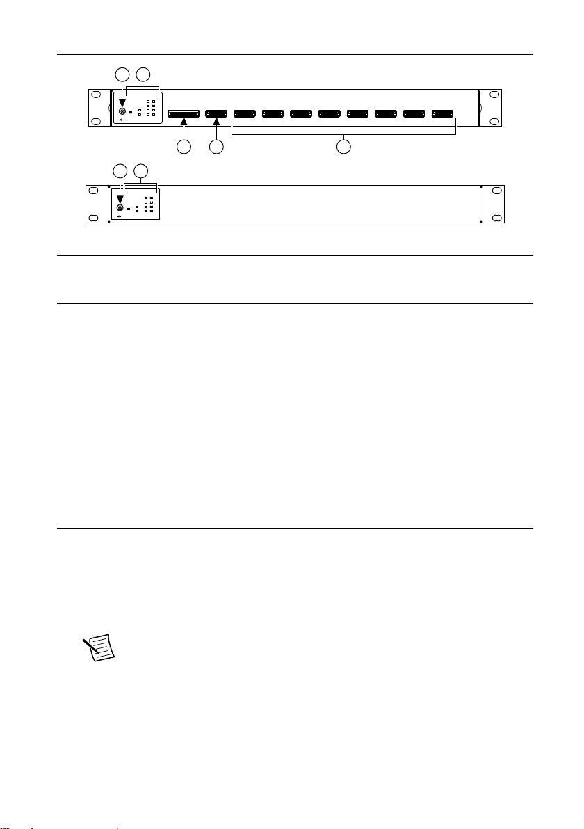
Figure 1. CPS-8910 Front and Rear Panels
12 VDC12 VDC
+
–
PWR/PWR/
STDBYSTDBY
UPUP
STREAMSTREAM
x4x4
x8x8
11
22
33
44
55
66
77
88
PORTPORT
UP STREAM
UP STREAM PORT 1
PORT 2 PORT 3 PORT 4 PORT 5 PORT 6
PORT 7
PORT 8
43
1 2
5
12 VDC12 VDC
++
––
PWR/PWR/
STDBYSTDBY
UPUP
STREAMSTREAM
x4x4
x8x8
11
22
33
44
55
66
77
88
PORTPORT
1 2
Front Panel
Rear Panel
1. 12 V Power Supply Input
2. LED Indicators
4. x4 Gen 1 Upstream Port
5. x4 Gen 1 Downstream Ports
3. x8 Gen 2 Upstream Port
Both the front and rear panels include the following LEDs:
• Power indicator—illuminates when the CPS-8910 is powered on.
• Up Stream
– Off—no connection.
– On—connected to a x8 upstream device.
– Blinking—connected to a x4 upstream device.
• Ports (1 through 8)
– Off—no connection.
– Blinking at 75% duty cycle—connected.
What You Need to Get Started
The following items are included in the device kit:
• Cabled PCI Express Switch Box x4 10 port
• Rack-mounting brackets
• CPS-8910 Getting Started Guide
• 12 V, 24 W power supply
Note If you are using the CPS-8910 with fiber optic cables, you must
purchase a 12 V, 50 W power supply with the proper connection from a
different source. Refer to the Specifications section of this document for power
supply connector information.
2 | ni.com | CPS-8910 Getting Started Guide
Page 3
The following items are available on ni.com:
• Copper or fiber optic PCI Express cable
Note The maximum copper cable length for the x8 upstream port is 3 m. All
other copper cables have a maximum length of 7 m. Refer to the
Electromagnetic Compatibility Guidelines section for more information.
Unpacking the Kit
Caution To prevent electrostatic discharge (ESD) from damaging the device,
ground yourself using a grounding strap or by holding a grounded object, such as
your computer chassis.
1. Touch the antistatic package to a metal part of the computer chassis.
2. Remove the device from the package and inspect the device for loose components or any
other sign of damage.
Caution Never touch the exposed pins of connectors.
Note Do not install a device if it appears damaged in any way.
3. Unpack any other items and documentation from the kit.
Store the device in the antistatic package when the device is not in use.
Electromagnetic Compatibility Guidelines
This product was tested and complies with the regulatory requirements and limits for
electromagnetic compatibility (EMC) stated in the product specifications. These requirements
and limits provide reasonable protection against harmful interference when the product is
operated in the intended operational electromagnetic environment.
This product is intended for use in industrial locations. However, harmful interference may
occur in some installations, when the product is connected to a peripheral device or test object,
or if the product is used in residential or commercial areas. To minimize interference with
radio and television reception and prevent unacceptable performance degradation, install and
use this product in strict accordance with the instructions in the product documentation.
Furthermore, any changes or modifications to the product not expressly approved by National
Instruments could void your authority to operate it under your local regulatory rules.
Caution To ensure the specified EMC performance, operate this product only with
shielded cables and accessories.
Caution To ensure the specified EMC performance, the length of all I/O cables
must be no longer than 100 m (328 ft).
CPS-8910 Getting Started Guide | © National Instruments | 3
Page 4

Caution To ensure the specified EMC performance, do not connect the power
input to a DC mains supply or to any supply requiring a connecting cable longer
than 3 m (10 ft). A DC mains supply is a local DC electricity supply network in the
infrastructure of a site or building.
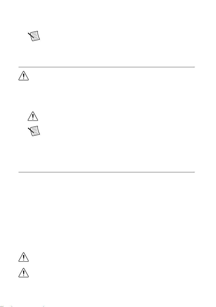
Installing the CPS-8910 in a Rack
The CPS-8910 comes with adjustable rack-mount ears for front or rear-facing installation, as
shown in the following figure. Complete the following steps to install the CPS-8910 and
connect devices to it.
Caution When mounting the equipment in the rack, do not create a hazardous
condition due to uneven mechanical loading.
1. Mount the CPS-8910 in the desired position by installing the rack-mount ears and
tightening the four rack-mounting screws as shown.
Figure 2. CPS-8910 Rack-Mount Ear Installation
2. Connect the 12 V power supply to the CPS-8910.
3. Connect the PCI Express host device to either the x8 or x4 upstream port connection.
4. Connect up to eight PCI Express expansion systems or devices to the x4 downstream
ports.
5. Power on the chassis or computer containing the PXI Express or PCI Express host.
4 | ni.com | CPS-8910 Getting Started Guide
Page 5

Providing Adequate Clearance
Apertures along both sides of the CPS-8910 facilitate cooling.
Place the CPS-8910 in an instrument rack so that the apertures have adequate ventilation.
Keep other equipment a minimum of 76.2 mm (3 in.) away from the air outlets on the sides of
the CPS-8910.
Specifications
This section contains the specifications for the CPS-8910. Specifications are subject to change
without notice. For the most recent CPS-8910 specifications, visit ni.com/manuals.
Interface
Upstream ports One Gen 2 x8 and one Gen 1 x4 PCI Express
upstream connectors with mutual lockout
mechanism
Downstream ports Eight Gen 1 PCI Express x4 downstream cable
connectors
LED indicators Single power indicator
One link status indicator per PCI Express
cable connector
Power Consumption
Copper cables 12 V, 20 W
Fiber optic cables 12 V, 54 W
Physical Characteristics
Maximum copper cable length
x8 upstream 3 m (118.11 in.)
x4 upstream 7 m (275.59 in.)
x4 downstream 7 m (275.59 in.)
Dimensions (H x W x D) 44.5 mm x 432 mm x 304 mm
(1.75 in. x 17 in. x 12 in.)
Power supply connector dimensions
Inner diameter 2.54 mm (0.1 in.)
Outer diameter 5.53 mm (0.218 in.)
CPS-8910 Getting Started Guide | © National Instruments | 5
Page 6

Barrel length 9.52 mm (0.375 in.)
Center positive
Caution Clean the CPS-8910 with a soft nonmetallic brush. Make sure that the
device is completely dry and free from contaminants before returning it to service.
Environmental
Operating environment
Operating temperature 0 °C to 55 °C
(32 °F to 140 °F)
Operating humidity 10% to 90% RH, noncondensing
Storage environment
Storage temperature -40 °C to 85 °C
(-40 °F to 185 °F)
Storage humidity 5% to 95% RH, noncondensing
Maximum altitude
Pollution Degree 2
Indoor use only.
2,000 m (800 mbar)
Safety
This product is designed to meet the requirements of the following electrical equipment safety
standards for measurement, control, and laboratory use:
• IEC 61010-1, EN 61010-1
• UL 61010-1, CSA 61010-1
Note For UL and other safety certifications, refer to the product label or the Online
Product Certification section.
Electromagnetic Compatibility
This product meets the requirements of the following EMC standards for electrical equipment
for measurement, control, and laboratory use:
• EN 61326-1 (IEC 61326-1): Class A emissions; Basic immunity
• EN 55011 (CISPR 11): Group 1, Class A emissions
• EN 55022 (CISPR 22): Class A emissions
• EN 55024 (CISPR 24): Immunity
• AS/NZS CISPR 11: Group 1, Class A emissions
• AS/NZS CISPR 22: Class A emissions
6 | ni.com | CPS-8910 Getting Started Guide
Page 7

• FCC 47 CFR Part 15B: Class A emissions
• ICES-001: Class A emissions
Note In the United States (per FCC 47 CFR), Class A equipment is intended for
use in commercial, light-industrial, and heavy-industrial locations. In Europe,
Canada, Australia and New Zealand (per CISPR 11) Class A equipment is intended
for use only in heavy-industrial locations.
Note Group 1 equipment (per CISPR 11) is any industrial, scientific, or medical
equipment that does not intentionally generate radio frequency energy for the
treatment of material or inspection/analysis purposes.
Note For EMC declarations and certifications, and additional information, refer to
the Online Product Certification section.
CE Compliance
This product meets the essential requirements of applicable European Directives, as follows:
• 2014/35/EU; Low-Voltage Directive (safety)
• 2014/30/EU; Electromagnetic Compatibility Directive (EMC)
Online Product Certification
Refer to the product Declaration of Conformity (DoC) for additional regulatory compliance
information. To obtain product certifications and the DoC for this product, visit ni.com/
certification, search by model number or product line, and click the appropriate link in the
Certification column.
Environmental Management
NI is committed to designing and manufacturing products in an environmentally responsible
manner. NI recognizes that eliminating certain hazardous substances from our products is
beneficial to the environment and to NI customers.
For additional environmental information, refer to the Minimize Our Environmental Impact
web page at ni.com/environment. This page contains the environmental regulations and
directives with which NI complies, as well as other environmental information not included in
this document.
Waste Electrical and Electronic Equipment (WEEE)
EU Customers At the end of the product life cycle, all NI products must be
disposed of according to local laws and regulations. For more information about
how to recycle NI products in your region, visit ni.com/environment/weee.
CPS-8910 Getting Started Guide | © National Instruments | 7
Page 8

电子信息产品污染控制管理办法(中国 RoHS)
中国客户 National Instruments 符合中国电子信息产品中限制使用某些有害物
质指令(RoHS)。关于 National Instruments 中国 RoHS 合规性信息,请登录
ni.com/environment/rohs_china。(For information about China RoHS
compliance, go to ni.com/environment/rohs_china.)
Worldwide Support and Services
The National Instruments website is your complete resource for technical support. At ni.com/
support, you have access to everything from troubleshooting and application development
self-help resources to email and phone assistance from NI Application Engineers.
Visit ni.com/services for NI Factory Installation Services, repairs, extended warranty, and
other services.
Visit ni.com/register to register your National Instruments product. Product registration
facilitates technical support and ensures that you receive important information updates from
NI.
A Declaration of Conformity (DoC) is our claim of compliance with the Council of the
European Communities using the manufacturer’s declaration of conformity. This system
affords the user protection for electromagnetic compatibility (EMC) and product safety. You
can obtain the DoC for your product by visiting ni.com/certification. If your product supports
calibration, you can obtain the calibration certificate for your product at ni.com/calibration.
National Instruments corporate headquarters is located at 11500 North Mopac Expressway,
Austin, Texas, 78759-3504. National Instruments also has offices located around the world.
For telephone support in the United States, create your service request at ni.com/support or
dial 1 866 ASK MYNI (275 6964). For telephone support outside the United States, visit the
Worldwide Offices section of ni.com/niglobal to access the branch office websites, which
provide up-to-date contact information, support phone numbers, email addresses, and current
events.
Refer to the NI Trademarks and Logo Guidelines at ni.com/trademarks for information on National Instruments trademarks.
Other product and company names mentioned herein are trademarks or trade names of their respective companies. For patents
covering National Instruments products/technology, refer to the appropriate location: Help»Patents in your software, the
patents.txt file on your media, or the National Instruments Patent Notice at ni.com/patents. You can find information about
end-user license agreements (EULAs) and third-party legal notices in the readme file for your NI product. Refer to the Export
Compliance Information at ni.com/legal/export-compliance for the National Instruments global trade compliance policy and
how to obtain relevant HTS codes, ECCNs, and other import/export data. NI MAKES NO EXPRESS OR IMPLIED WARRANTIES
AS TO THE ACCURACY OF THE INFORMATION CONTAINED HEREIN AND SHALL NOT BE LIABLE FOR ANY ERRORS.
U.S. Government Customers: The data contained in this manual was developed at private expense and is subject to the
applicable limited rights and restricted data rights as set forth in FAR 52.227-14, DFAR 252.227-7014, and DFAR 252.227-7015.
© 2015 National Instruments. All rights reserved.
376463A-01 Dec15
 Loading...