

Page 1

FieldPoint Operating Instructions
FP-AI-111 and cFP-AI-111
16-Channel, 16-Bit Analog Milliamp
Input Modules
These operating instructions describe how to install and use the
National Instruments FP-AI-111 and cFP-AI-111 analog input
modules (referred to inclusively as the [c]FP-AI-111). For
information about configuring and accessing the [c]FP-AI-111
over a network, refer to the user manual for the FieldPoint network
module you are using.
Features
The [c]FP-AI-111 is a FieldPoint analog input module with the
following features:
• 16 single-ended analog current input channels
• Three input ranges: ±20, 0–20, and 4–20 mA
• 16-bit resolution
• Three filter settings: 50, 60, and 500 Hz
• Hot swappable
• 2,300 V
• –40 to 70 °C operation
transient overvoltage protection
rms
Installing the FP-AI-111
The FP-AI-111 mounts on a FieldPoint terminal base (FP-TB-x),
which provides operating power to the module. Installing the
FP-AI-111 onto a powered terminal base does not disrupt the
operation of the bank.
FieldPoint™, National Instruments™, NI™, and ni.com™ are trademarks of National Instruments Corporation.
Product and compa ny names mentioned herein are trade marks or trade names of their respe ctive companies.
For patents covering National Instruments products, refer to the appropriate location: Help»Patents in your software,
the
patents.txt file on your CD, or ni.com/p atents.
373281B-01 April 2003
© 2002–2003 National Instruments Corp. All rights reserved.
Page 2
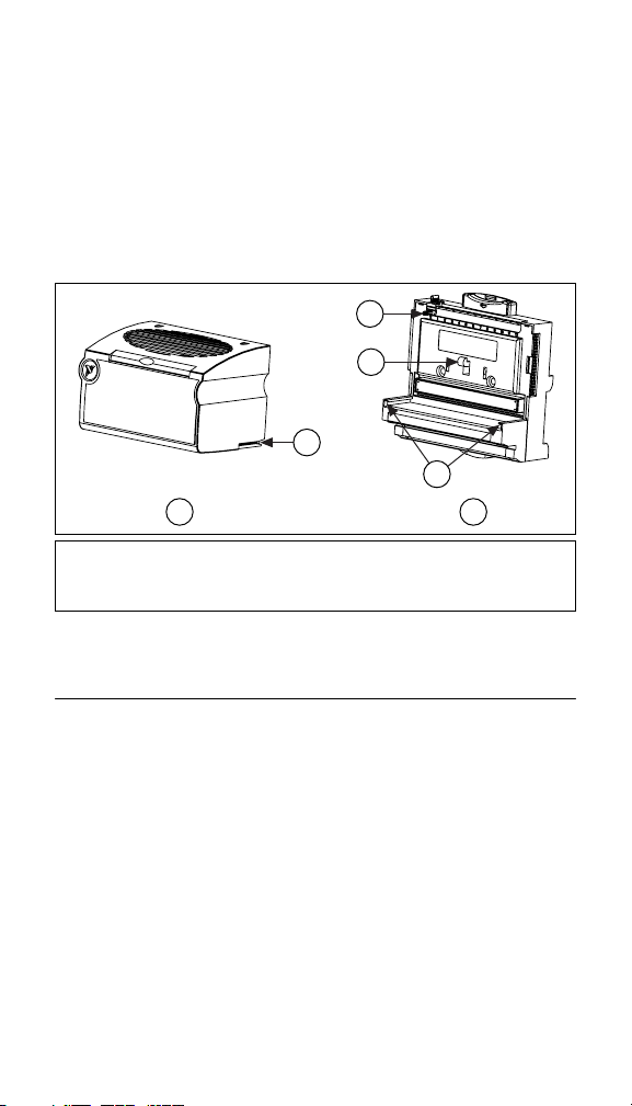
To install the FP-AI-111, refer to Figure 1 and complete the
following steps:
1. Slide the terminal base key to either position X, used for any
module, or position 1, used for the FP-AI-111 module.
2. Align the FP-AI-111 alignment slots with the guide rails on the
terminal base.
3. Press firmly to seat the FP-AI-111 on the terminal base. When
the module is firmly seated, the terminal base latch locks it into
place.
4
5
3
6
1
1 I/O Module
2Terminal Base
3 Alignment Slot
4Key
5Latch
6 Guide Rails
Figure 1. Installing the FP-AI-111
2
Installing the cFP-AI-111
The cFP-AI-111 mounts on a Compact FieldPoint backplane
(cFP-BP-x), which provides operating power to the module.
Installing the cFP-AI-111 onto a powered backplane does not
disrupt the operation of the bank.
To install the cFP-AI-111, refer to Figure 2 and complete the
following steps:
1. Align the captive screws on the cFP-AI-111 with the holes on
the backplane. The alignment keys on the cFP-AI-111 prevent
backward insertion.
2. Press firmly to seat the cFP-AI-111 on the backplane.
3. Using a number 2 Phillips screwdriver with a shank of at least
64 mm (2.5 in.) length, tighten the captive screws to 1.1 N ⋅ m
FP-AI-111 and cFP-AI-111 2 ni.com
Page 3
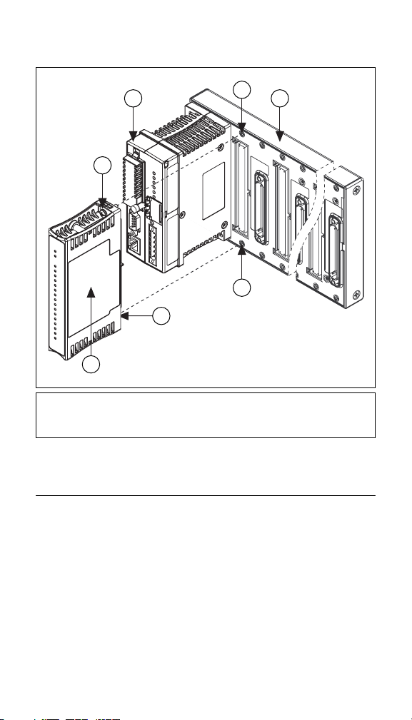
(10 lb ⋅ in.) of torque. The nylon coating on the screws prevents
them from loosening.
3 5
2
2
1
1cFP-AI-111
2 Captive Screws
3 cFP Controller Module
Figure 2. Installing the cFP-AI-111
4 Screw Holes
5 cFP Backplane
Wiring the [c]FP-AI-111
4
4
The FP-TB-x terminal bases have connections for each of the
16 input channels on the FP-AI-111 and for an external supply to
power field devices. The cFP-CB-x connector blocks provide the
same connections for the cFP-AI-111.
Table 1 lists the terminal assignments for the signals associated
with each channel. The terminal assignments are the same for the
FP-TB-x terminal bases and the cFP-CB-x connector blocks.
© National Instruments Corp. 3 FP-AI-111 and cFP-AI-111
Page 4

Table 1. Terminal Assignments
Terminal Numbers
Channel
0 1 17 18
1 2 17 18
2 3 19 20
3 4 19 20
4 5 21 22
5 6 21 22
6 7 23 24
7 8 23 24
8 9 25 26
9 10 25 26
10 11 27 28
11 12 27 28
12 13 29 30
13 14 29 30
14 15 31 32
15 16 31 32
I
in
V
SUP
COM
Each channel has one input terminal (Iin) for current input. All
16 current inputs are referenced to the COM terminals. If you are
using an external supply to power field devices, connect the power
supply to the V and C terminals of the terminal base or connector
block. Field devices source power from the V
and COM
SUP
terminals. Refer to the Measuring Current with the [c]FP-AI-111
section for detailed wiring diagrams.
Caution Cascading power between two modules defeats
isolation between those modules. Cascading power from
the network module defeats all isolation between
modules in the FieldPoint bank.
FP-AI-111 and cFP-AI-111 4 ni.com
Page 5
Measuring Current with the [c]FP-AI-111
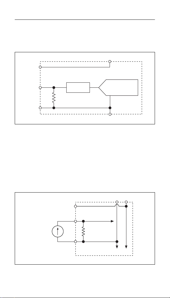
The [c]FP-AI-111 has 16 single-ended input channels. All
16 channels share a common ground reference that is isolated
from other modules in the FieldPoint system. Figure 3 shows the
analog input circuitry on one channel.
V
V
SUP
COM
I
IN
Filter
16-Bit
Isolated ADC
C
Figure 3. FP-AI-111 Analog Input Circuitry
The current input ranges are ±20, 0–20, and 4–20 mA. The input
channels have overcurrent protection up to ±30 mA. The
[c]FP-AI-111 reads current flowing into the I
terminal as positive
in
and current flowing out of the terminal as negative. Current flows
into the I
terminal, goes through a 100 Ω resistor, and flows out
in
from the COM or C terminal.
Figure 4 shows how to connect a current source without an external
power supply to one channel of the [c]FP-AI-111.
VC
V
Current
Source
SUP
COM
I
IN
To Analog
Input Circuitry
100 Ω
To Next Channel
FP-AI-111
Figure 4. Current Source without External Power Supply
© National Instruments Corp. 5 FP-AI-111 and cFP-AI-111
Page 6

Figure 5 shows how to connect a loop-powered current transducer
to one channel of the [c]FP-AI-111.
+
External
Powe r
Supply
–
VC
Loop-Powered
Current
Transducer
V
SUP
COM
I
IN
FP-AI-111
To Analog
Input Circuitry
100 Ω
To Next Channel
Figure 5. Loop-Powered Current Transducer
Figure 6 shows how to connect a three-wire powered current
transducer to one channel of the [c]FP-AI-111.
+
External
Powe r
Supply
–
VC
V
SUP
Three-Wire
Powered
Current
Transducer
+
OUT
–
COM
I
IN
To Analog
Input Circuitry
100 Ω
To Next Channel
FP-AI-111
Figure 6. Three-Wire Powered Current Transducer
FP-AI-111 and cFP-AI-111 6 ni.com
Page 7

Input Ranges
To prevent inaccurate readings, select an input range such that the
signal you are measuring does not exceed either end of the range.
Overranging
The [c]FP-AI-111 has an overranging feature that measures 5%
beyond the nominal values of each range. For example, the actual
measurement limit of the ±20 mA range is ±21 mA. The
overranging feature enables the [c]FP-AI-111 to compensate for
field devices with span errors of up to 5% of full scale. Also,
with the overranging feature, a noisy signal near full scale does
not create rectification errors. FieldPoint software accounts for the
5% overranging feature and shows the ranges accordingly. For
example, the ±20 mA range appears in FieldPoint software as
±21 mA.
Filter Settings
Three filter settings are available for each channel. The filters on
the [c]FP-AI-111 input channels are comb filters that provide
notches of rejection at multiples, or harmonics, of a fundamental
frequency. You can select a fundamental frequency of 50, 60,
or 500 Hz. The [c]FP-AI-111 applies 95 dB of rejection at the
fundamental frequency and at least 60 dB of rejection at each of the
harmonics. In many cases, most of the noise components of input
signals are related to the local AC power line frequency, so a filter
setting of either 50 or 60 Hz is best.
Update Rate
The rate at which the [c]FP-AI-111 samples current inputs is
determined by the ranges and filter settings you select. When all
channels are set to the same range and to 50 or 60 Hz filters,
the module samples each channel every 1.23 s or every 1.05 s,
respectively. When all channels are set to 500 Hz filters, the
module samples each channel every 0.29 s. If you select different
filter settings or ranges for the different channels, you can use the
following formula to determine the sampling rate:
(number of channels with 50 Hz filters) × 70 ms +
(number of ranges used with these channels) × 113 ms +
(number of channels with 60 Hz filters) × 60 ms +
(number of ranges used with these channels) × 93 ms +
(number of channels with 500 Hz filters) × 18 ms +
(number of ranges used with these channels) × 3 ms =
Update Rate
© National Instruments Corp. 7 FP-AI-111 and cFP-AI-111
Page 8

Therefore, setting any unused channels to the 500 Hz filter setting
improves the sampling rate of the module. For example, if one
channel is set for a 60 Hz filter, and the other 15 channels are set
for 500 Hz, each channel is sampled every 0.42 s (2.5 times faster
than if all 16 channels are set for 60 Hz filtering).
The sampling rate does not affect the rate at which the network
module reads the data. The [c]FP-AI-111 always has data available
for the network module to read; the sampling rate is the rate at
which this data is updated. Set up your application so that the
sampling rate is faster than the rate at which the network module
polls the [c]FP-AI-111 for data.
Status Indicators
The [c]FP-AI-111 has two green status LEDs, POWER and
READY. After you insert the [c]FP-AI-111 into a terminal base or
backplane and apply power to the connected network module, the
green POWER indicator lights and the [c]FP-AI-111 informs the
network module of its presence. When the network module
recognizes the [c]FP-AI-111, it sends initial configuration
information to the [c]FP-AI-111. After the [c]FP-AI-111 receives
this initial information, the green READY indicator lights and the
module is in normal operating mode.
Upgrading the FieldPoint Firmware
You may need to upgrade the FieldPoint firmware when you add
new I/O modules to the FieldPoint system. For information on
determining which firmware you need and how to upgrade the
firmware, go to
ni.com/info and enter fpmatrix.
Isolation and Safety Guidelines
Caution Read the following information before
attempting to connect the [c]FP-AI-111 to any circuits
that may contain hazardous voltages.
This section describes the isolation of the [c]FP-AI-111 and its
compliance with international safety standards. The field wiring
connections are isolated from the backplane and the inter-module
communication bus. The isolation is provided by the module,
which has optical and galvanic isolation barriers designed and
tested to protect against transient fault voltages of up to 2,300 V
FP-AI-111 and cFP-AI-111 8 ni.com
rms
.
Page 9

Follow these guidelines to ensure a safe total system:
• The [c]FP-AI-111 has a safety isolation barrier between the
I/O channels and the inter-module communication bus. There
is no isolation between channels unless otherwise noted. If any
of the channels on a module are wired at a hazardous potential,
make sure that all other devices or circuits connected to that
module are properly insulated from human contact.
•Do not share the external supply voltages (the V and C
terminals) with other devices (including other FieldPoint
devices), unless those devices are isolated from human contact.
• For Compact FieldPoint, you must connect the protective earth
(PE) ground terminal on the cFP-BP-x backplane to the system
safety ground. The backplane PE ground terminal has the
following symbol stamped beside it: . Connect the
backplane PE ground terminal to the system safety ground
using 14 AWG (1.6 mm) wire with a ring lug. Use the 5/16 in.
panhead screw shipped with the backplane to secure the ring
lug to the backplane PE ground terminal.
• As with any hazardous voltage wiring, make sure that all
wiring and connections meet applicable electrical codes and
commonsense practices. Mount terminal bases and backplanes
in an area, position, or cabinet that prevents accidental or
unauthorized access to wiring that carries hazardous voltages.
• Operate the [c]FP-AI-111 only at or below Pollution Degree 2.
Pollution Degree 2 means that only nonconductive pollution
occurs in most cases. Occasionally, however, a temporary
conductivity caused by condensation must be expected.
• Refer to the FieldPoint product label for regulatory
certification under hazardous location standards. If the
FieldPoint product is not certified for operation in hazardous
locations, do not operate it in an explosive atmosphere or
where there may be flammable gases or fumes.
© National Instruments Corp. 9 FP-AI-111 and cFP-AI-111
Page 10

Specifications
The following specifications are typical for the range –40 to 70 °C
unless otherwise noted. Gain error is calculated as a percentage of
input signal value.
Input Characteristics
Number of channels..........................16
ADC resolution................................. 16 bits at 50 or 60 Hz;
Type of ADC.....................................Delta-sigma
Input impedance................................100 Ω
Overcurrent protection......................±30 mA
Input noise (50 or 60 Hz filter)......... 0.3 µA
Input signal ranges (FieldPoint software shows the ranges with 5%
overranging.)
12 bits at 500 Hz
rms
Nominal
Input Range
Current 4–20 mA
0–20 mA
±20 mA
* Includes quantization errors and rms noise with the filter set to
50 or 60 Hz.
With
Overranging
3.5–21 mA
0–21 mA
±21 mA
Effective
Resolution*
0.5 µA
0.5 µA
0.7 µA
Filter settings (software selectable by channel)
Filter Settings
Characteristic
Update time* 1.23 s 1.05 s 0.29 s
Input bandwidth (–3 dB) 13 Hz 16 Hz 130 Hz
* Applies when all 16 channels are set to the same filter setting and
range.
50 Hz 60 Hz 500 Hz
Normal-mode rejection
(at 50/60 Hz).....................................95 dB (with 50/60 Hz filter)
Nonlinearity......................................0.0015%
Offset error........................................ ±0.1 µA
Offset error drift................................±20 nA/°C
FP-AI-111 and cFP-AI-111 10 ni.com
Page 11

Gain error
25 °C...........................................±0.03%
–40 to 70 °C ...............................±0.2%
Gain error drift..................................±40 ppm/°C
Physical Characteristics
Indicators ..........................................Green POWER and
READY indicators
Weight
FP-AI-111...................................140 g (4.8 oz)
cFP-AI-111................................. 110 g (3.7 oz)
Power Requirements
Power from network module ............350 mW
Isolation Voltage
Channel-to-channel isolation............No isolation between
Transient overvoltage........................2,300 V
channels
rms
Environmental
FieldPoint modules are intended for indoor use only. For outdoor
use, they must be mounted inside a sealed enclosure.
Operating temperature ......................–40 to 70 °C
Storage temperature..........................–55 to 85 °C
Humidity...........................................10 to 90% RH,
Maximum altitude.............................2,000 m; at higher altitudes
Pollution Degree ..............................2
noncondensing
the isolation voltage ratings
must be lowered
© National Instruments Corp. 11 FP-AI-111 and cFP-AI-111
Page 12

Shock and Vibration
These specifications apply only to the cFP-AI-111.
NI recommends Compact FieldPoint if your application is subject
to shock and vibration.
Operating vibration, random
(IEC 60068-2-64)..............................10–500 Hz, 5 g
rms
Operating vibration, sinusoidal
(IEC 60068-2-6)................................ 10–500 Hz, 5 g
Operating shock
(IEC 60068-2-27)..............................50 g, 3 ms half sine,
18 shocks at 6 orientations;
30 g, 11 ms half sine,
18 shocks at 6 orientations
Safety
This product is designed to meet the requirements of the following
standards of safety for electrical equipment for measurement,
control, and laboratory use:
• IEC 61010-1, EN 61010-1
• UL 3121-1, UL 61010C-1
• CAN/CSA C22.2 No. 1010.1
For UL, hazardous location, and other safety certifications, refer to
the product label or to
ni.com.
Electromagnetic Compatibility
CE, C-Tick, and FCC Part 15 (Class A) Compliant
Emissions..........................................EN 55011 Class A at 10 m
Immunity...........................................EN 61326:1997 + A2:2001,
FCC Part 15A above 1 GHz
Tab le 1
Note For EMC compliance, operate this device with
shielded cabling.
FP-AI-111 and cFP-AI-111 12 ni.com
Page 13
CE Compliance
This product meets the essential requirements of applicable
European Directives, as amended for CE Marking, as follows:
Low-Voltage Directive (safety).........73/23/EEC
Electromagnetic Compatibility
Directive (EMC) ...............................89/336/EEC
Note Refer to the Declaration of Conformity (DoC) for
this product for any additional regulatory compliance
information. To obtain the DoC for this product, click
Declarations of Conformity Information at
ni.com/hardref.nsf/.
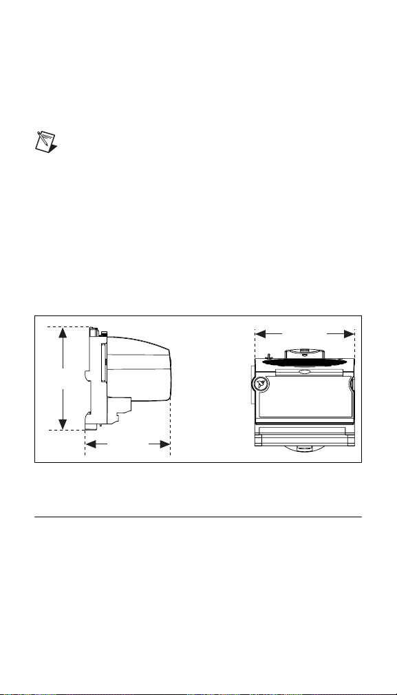
Mechanical Dimensions
Figure 7 shows the mechanical dimensions of the FP-AI-111
installed on a terminal base. If you are using the cFP-AI-111, refer
to the Compact FieldPoint controller user manual for the
dimensions and cabling clearance requirements of the Compact
FieldPoint system.
107.19 mm
(4.22 in.)
109.5 mm
(4.31 in.)
91.44 mm
(3.60 in.)
Figure 7. FP-AI-111 Mechanical Dimensions
Where to Go for Support
For more information about setting up the FieldPoint system, refer
to these National Instruments documents:
• FieldPoint network module user manual
• Other FieldPoint I/O module operating instructions
• FieldPoint terminal base and connector block operating
instructions
© National Instruments Corp. 13 FP-AI-111 and cFP-AI-111
Page 14

Go to ni.com/support for the most current manuals, examples,
and troubleshooting information.
For telephone support in the United States, create your service
request at
ni.com/ask and follow the calling instructions or dial
512 795 8248. For telephone support outside the United States,
contact your local branch office:
Australia61296728846, Austria4306624579900,
Belgium32027570020, Brazil551132623599,
Canada (Calgary) 403 274 9391,
Canada (Montreal) 514 288 5722,
Canada (Ottawa) 613 233 5949, Canada (Québec) 514 694 8521,
Canada (Toronto) 905 785 0085,
Canada (Vancouver) 514 685 7530, China 86 21 6555 7838,
Czech Republic 420 2 2423 5774, Denmark 45 45 76 26 00,
Finland 385 0 9 725 725 11, France 33 0 1 48 14 24 24,
Germany 49 0 89 741 31 30, Greece 30 2 10 42 96 427,
Hong Kong 2645 3186, India 91 80 51190000,
Israel972036393737,Italy3902413091,
Japan 81 3 5472 2970, Korea 82 02 3451 3400,
Malaysia 603 9059 6711, Mexico 001 800 010 0793,
Netherlands 31 0 348 433 466, New Zealand 64 09 914 0488,
Norway47032277300, Poland480223390150,
Portugal 351 210 311 210, Russia 7 095 238 7139,
Singapore 65 6 226 5886, Slovenia 386 3 425 4200, South
Africa270118058197, Spain34916400085,
Sweden 46 0 8 587 895 00, Switzerland 41 56 200 51 51,
Taiwan 886 2 2528 7227, United Kingdom 44 0 1635 523545
FP-AI-111 and cFP-AI-111 14 ni.com
 Loading...