

Page 1

DAQ
BNC-2140 User Manual
Dynamic Signal Acquisition
Signal Conditioning Accessory
BNC-2140 User Manual
February 2001 Edition
Part Number 321933C-01
Page 2

Worldwide Technical Support and Product Information
ni.com
National Instruments Corporate Headquarters
11500 North Mopac Expressway Austin, Texas 78759-3504 USA Tel: 512 794 0100
Worldwide Offices
Australia 03 9879 5166, Austria 0662 45 79 90 0, Belgium 02 757 00 20, Brazil 011 284 5011,
Canada (Calgary) 403 274 9391, Canada (Ottawa) 613 233 5949, Canada (Québec) 514 694 8521,
China (Shanghai) 021 6555 7838, China (ShenZhen) 0755 3904939, Denmark 45 76 26 00,
Finland 09 725 725 11, France 01 48 14 24 24, Germany 089 741 31 30, Greece 30 1 42 96 427,
Hong Kong 2645 3186, India 91805275406, Israel 03 6120092, Italy 02 413091, Japan 03 5472 2970,
Korea 02 596 7456, Mexico 5 280 7625, Netherlands 0348 433466, New Zealand 09 914 0488,
Norway 32 27 73 00, Poland 0 22 528 94 06, Portugal 351 1 726 9011, Singapore 2265886, Spain 91 640 0085,
Sweden 08 587 895 00, Switzerland 056 200 51 51, Taiwan 02 2528 7227, United Kingdom 01635 523545
For further support information, see the Technical Support Resources appendix. To comment on the
documentation, send e-mail to techpubs@ni.com
© Copyright 1998, 2001 National Instruments Corporation. All rights reserved.
Page 3

Important Information
Warranty
The BNC-2140 is warranted against defects in materials and workmanship for a period of one year from the date of shipment, as evidenced by
receipts or other documentation. National Instruments will, at its option, repair or replace equipment that proves to be defective during the
warranty period. This warranty includes parts and labor.
The media on which you receive National Instruments software are warranted not to fail to execute programming instructions, due to defects
in materials and workmanship, for a period of 90 days from date of shipment, as evidenced by receipts or other documentation. National
Instruments will, at its option, repair or replace software media that do not execute programming instructions if National Instruments receives
notice of such defects during the warranty period. National Instruments does not warrant that the operation of the software shall be
uninterrupted or error free.
A Return Material Authorization (RMA) number must be obtained from the factory and clearly marked on the outside of the package before
any equipment will be accepted for warranty work. National Instruments will pay the shipping costs of returning to the owner parts which are
covered by warranty.
National Instruments believes that the information in this document is accurate. The document has been carefully reviewed for technical
accuracy. In the event that technical or typographical errors exist, National Instruments reserves the right to make changes to subsequent
editions of this document without prior notice to holders of this edition. The reader should consult National Instruments if errors are suspected.
In no event shall National Instruments be liable for any damages arising out of or related to this document or the information contained in it.
XCEPT AS SPECIFIED HEREIN,NATIONAL INSTRUMENTS MAKES NO WAR RANTIES, EXPRESS OR IMPLIED, AND SPECIFICALLY DISCLAIMS ANY WARRANTY OF
E
MERCHANTABILITY OR FITNESS FOR A PARTICULAR PURPOSE
NATIONAL INSTRUMENTS SHALL BE LIMITED TO THE AMOUNT THERETOFORE PAID BY THE CUSTOMER.NATIONAL INSTRUMENTS WILL NOT BE LIABLE FOR
DAMAGES RESULTING FROM LOSS OF DATA
. This limitation of the liability of National Instruments will apply regardless ofthe form of action, whether in contract ortort, including
THEREOF
negligence. Any action against National Instruments must be brought within one year after the cause of action accrues. National Instruments
shall not be liable for any delay in performance due to causes beyond its reasonable control. The warranty provided herein does not cover
damages, defects, malfunctions, or service failures caused by owner’s failure to follow the National Instruments installation, operation, or
maintenance instructions; owner’s modification of the product; owner’s abuse, misuse, or negligent acts; and power failure or surges, fire,
flood, accident, actions of third parties, or other events outside reasonable control.
, PROFITS, USE OF PRODUCTS, OR INCIDENTAL OR CONSEQUENTIAL DAMAGES, EVEN IF ADVISED OF THE POSSIBILITY
Copyright
Under the copyright laws, this publication may not be reproduced or transmitted in any form, electronic or mechanical, including photocopying,
recording, storing in an information retrieval system, or translating, in whole or in part, without the prior written consent of National
Instruments Corporation.
Trademarks
National Instruments™and ni.com™are trademarks of National Instruments Corporation.
ICP® is a registered trademark of PCB Piezotronics, Inc. Other product and company names mentioned herein are trademarks or trade names
of their respective companies.
Product and company names mentioned herein are trademarks or trade names of their respective companies.
WARNING REGARDING USE OF NATIONAL INSTRUMENTS PRODUCTS
(1) NATIONAL INSTRUMENTS PRODUCTS ARE NOT DESIGNED WITH COMPONENTS AND TESTING FOR A LEVEL OF
RELIABILITY SUITABLE FOR USE IN OR IN CONNECTION WITH SURGICAL IMPLANTS OR AS CRITICAL COMPONENTS IN
ANY LIFE SUPPORT SYSTEMS WHOSE FAILURE TO PERFORM CAN REASONABLY BE EXPECTED TO CAUSE SIGNIFICANT
INJURY TO A HUMAN.
(2) IN ANY APPLICATION, INCLUDING THE ABOVE, RELIABILITY OF OPERATION OF THE SOFTWARE PRODUCTS CAN BE
IMPAIRED BY ADVERSE FACTORS, INCLUDING BUT NOT LIMITED TO FLUCTUATIONS IN ELECTRICAL POWER SUPPLY,
COMPUTER HARDWARE MALFUNCTIONS, COMPUTER OPERATING SYSTEM SOFTWARE FITNESS, FITNESS OF COMPILERS
AND DEVELOPMENT SOFTWARE USED TO DEVELOP AN APPLICATION, INSTALLATION ERRORS, SOFTWARE AND
HARDWARE COMPATIBILITY PROBLEMS, MALFUNCTIONS OR FAILURES OF ELECTRONIC MONITORING OR CONTROL
DEVICES, TRANSIENT FAILURES OF ELECTRONIC SYSTEMS (HARDWARE AND/OR SOFTWARE), UNANTICIPATED USES OR
MISUSES, OR ERRORS ON THE PART OF THE USER OR APPLICATIONS DESIGNER (ADVERSE FACTORS SUCH AS THESE ARE
HEREAFTER COLLECTIVELY TERMED “SYSTEM FAILURES”). ANY APPLICATION WHERE A SYSTEM FAILURE WOULD
CREATE A RISK OF HARM TO PROPERTY OR PERSONS (INCLUDING THE RISK OF BODILY INJURY AND DEATH) SHOULD
NOT BE RELIANT SOLELY UPON ONE FORM OF ELECTRONIC SYSTEM DUE TO THE RISK OF SYSTEM FAILURE. TO AVOID
DAMAGE, INJURY, OR DEATH, THE USER OR APPLICATION DESIGNER MUST TAKE REASONABLY PRUDENT STEPS TO
PROTECT AGAINST SYSTEM FAILURES, INCLUDING BUT NOT LIMITED TO BACK-UP OR SHUT DOWN MECHANISMS.
BECAUSE EACH END-USER SYSTEM IS CUSTOMIZED AND DIFFERS FROM NATIONAL INSTRUMENTS' TESTING
PLATFORMS AND BECAUSE A USER OR APPLICATION DESIGNER MAY USE NATIONAL INSTRUMENTS PRODUCTS IN
COMBINATION WITH OTHER PRODUCTS IN A MANNER NOT EVALUATED OR CONTEMPLATED BY NATIONAL
INSTRUMENTS, THE USER OR APPLICATION DESIGNER IS ULTIMATELY RESPONSIBLE FOR VERIFYING AND VALIDATING
THE SUITABILITY OF NATIONAL INSTRUMENTS PRODUCTS WHENEVER NATIONAL INSTRUMENTS PRODUCTS ARE
INCORPORATED IN A SYSTEM OR APPLICATION, INCLUDING, WITHOUT LIMITATION, THE APPROPRIATE DESIGN,
PROCESS AND SAFETY LEVEL OF SUCH SYSTEM OR APPLICATION.
.CUSTOMER’S RIGHT TO RECOVER DAMAGES CAUSED BY FAULT OR NEGLIGENCE ON THE PART OF
Page 4

Conventions
The following conventions are used in this manual:
<> Angle brackets that contain numbers separated by an ellipsis represent a
range of values associated with a bit or signal name—for example,
ACH<3..0>.
This icon denotes a note, which alerts you to important information.
This icon denotes a caution, which advises you of precautions to take to
avoid injury, data loss, or a system crash.
italic Italic text denotes variables, emphasis, or a cross reference.
monospace
Text in this font denotes text or characters that you should enter from the
keyboard, sections of code, programming examples, and syntax examples.
This font is also used for the proper names of disk drives, paths, directories,
programs, subprograms, subroutines, device names, functions, operations,
variables, filenames and extensions, and code excerpts.
Page 5

Contents
Chapter 1
Introduction
What You Need to Get Started ......................................................................................1-2
Unpacking......................................................................................................................1-2
Optional Equipment.......................................................................................................1-3
Chapter 2
Installation and Configuration
Installation .....................................................................................................................2-1
Device Configuration.....................................................................................................2-1
Chapter 3
Signal Connections
I/O Connectors...............................................................................................................3-2
Analog Input Signal Connections ..................................................................................3-5
Analog Output Signal Connections ............................................................................... 3-5
Chapter 4
Theory of Operation
Functional Overview...................................................................................................... 4-1
Analog Input Circuitry...................................................................................................4-2
Analog Output................................................................................................................4-3
Appendix A
Specifications
Appendix B
Technical Support Resources
© National Instruments Corporation v BNC-2140 User Manual
Page 6

Contents
Glossary
Index
Figures
Figure 2-1. Switch Settings and Signal Connections...............................................2-2
Figure 3-1. BNC-2140 External 68-Pin Analog Connector .................................... 3-3
Figure 4-1. BNC-2140 Block Diagram ................................................................... 4-1
Tables
Table 3-1. BNC Analog I/O Connector Signal Descriptions ................................. 3-2
Table 3-2. 68-Pin Analog I/O Connector Signal Descriptions............................... 3-4
BNC-2140 User Manual vi ni.com
Page 7

Introduction
This manual describes the electrical and mechanical aspects of the
BNC-2140 accessory and contains information concerning its operation.
This chapter describes the BNC-2140 accessory, lists what you need to get
started, explains how to unpack your BNC-2140, and describes optional
equipment.
The BNC-2140 is a signal conditioning accessory specifically designed for
use with a dynamic signal acquisition (DSA) device. It interfaces four BNC
signal inputs and two BNC signal outputs directly to National Instruments
DSA products including the PCI-4451, PCI-4452, NI 4551, and NI 4552.
The BNC-2140 connects to Integrated Circuit Piezoelectric (ICP
accelerometers and microphone preamplifiers as well as any other
voltage source whose output is less than ±42.4 V.
Each input channel has an independent 4 mA current source suitable for
use with ICP-type accelerometers and microphone preamplifiers. You can
manually enable or disable the ICP signal conditioning on a per-channel
basis. With ICP disabled, a BNC-2140 input channel acts as a direct voltage
input. You can manually switch each input channel and each output channel
from differential (DIFF) to single-ended (SE) mode. In SE mode, the BNC
shell is tethered to a clean analog ground through a 50 Ω resistor.
1
®
)
The BNC-2140 receives power for ICP signal conditioning from the DSA
plug-in device through the 68-pin high-density connector. A green LED
indicates when the ICP circuitry is powered on. When you do not require
ICP signal conditioning, you can manually turn off the power to the
circuits.
© National Instruments Corporation 1-1 BNC-2140 User Manual
Page 8

Chapter 1 Introduction
What You Need to Get Started
To set up and use your BNC-2140 device, you will need the following:
❑
BNC-2140
❑
One of the following DSA devices and its documentation:
– NI 4451 for PCI
– NI 4452 for PCI
– NI 4551for PCI
– NI 4552 for PCI
❑
This manual
❑
Your computer
❑
SHC68-C68-A1 analog cable
Unpacking
For more information, refer to
Instruments Application Note 25, Field Wiring and Noise Considerations.
Your BNC-2140 is shipped in an antistatic plastic package to prevent
electrostatic damage to the device. Several components on the device can
be damaged by electrostatic discharge. To avoid such damage in handling
the device, take the following precautions:
• Ground yourself with a grounding strap or by holding a grounded
object.
• Touch the plastic package to a metal part of your computer chassis
before removing the device from the package.
• Never touch exposed connector pins.
Remove the device from the package and inspect the device for loose
components or any other sign of damage. Notify National Instruments if the
device appears damaged in any way. Do not install a damaged device into
your computer.
ni.com/appnotes.nsf/
for the National
BNC-2140 User Manual 1-2 ni.com
Page 9

Optional Equipment
If your application requires that you use transducers with microdot
connectors, use the BNC plug to screw-on receptacle adapter, part number
033-0101-0001, from Microdot Connectors. This accessory allows you to
connect BNC and microdot connectors.
If your application requires that you use a prepolarized microphone with a
microphone preamplifier, contact Brüel and Kjær.
Chapter 1 Introduction
© National Instruments Corporation 1-3 BNC-2140 User Manual
Page 10

Installation and Configuration
This chapter explains how to install and configure your BNC-2140
accessory.
Installation
2
Caution
You must turn the power off to your computer before installing the BNC-2140.
The following are general installation instructions:
1. Insert either end of your SHC68-C68-A1 analog cable into the 68-pin
connector on the BNC-2140. Insert the other end into the 68-pin
connector on the DSA plug-in device.
2. Tighten the jackscrews finger-tight on both ends of the cable.
3. Check the installation.
4. Turn on your computer.
The BNC-2140 accessory is now installed.
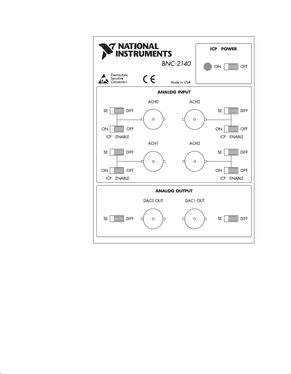
Device Configuration
You must manually configure the BNC-2140 accessory by setting the
channel switches. You can configure each input channel to have ICP signal
conditioning enabled or disabled, and for DIFF and SE measurements.
When ICP signal conditioning is enabled large DC offset voltages can
occur on signal inputs due to the output bias voltage requirements of the
ICP transducer you are using. To remove this offset you must enable
AC coupling on the affected input channels of the DSA device. You can
also configure each output channel for DIFF or SE measurements. You can
turn the power on or off for the ICP signal conditioning circuitry. If you do
not require ICP signal conditioning, turn off the ICP power. Refer to
Figure 2-1 for the location of the switches.
Note
You can connect or disconnect BNC cables carrying signals without turning off the
computer.
© National Instruments Corporation 2-1 BNC-2140 User Manual
Page 11
Chapter 2 Installation and Configuration
®
Figure 2-1. Switch Settings and Signal Connections
BNC-2140 User Manual 2-2 ni.com
Page 12

Signal Connections
This chapter describes how to connect input and output signals to your
BNC-2140.
You can connect the external analog signals through six BNC connectors.
Four of the BNC connectors are for input signals and two of them are for
output signals.
The SHC68-C68-A1 shielded cable connects the BNC-2140 internal
analog signal connector to the DSA plug-in device. A single 68-pin 0.8 mm
VHDCI connector connects the analog I/O signals to the shielded cable.
3
© National Instruments Corporation 3-1 BNC-2140 User Manual
Page 13

Chapter 3 Signal Connections
I/O Connectors
Table 3-1 describes the pin assignments for the six external I/O BNC
connectors.
Table 3-1. BNC Analog I/O Connector Signal Descriptions
Signal Name Reference Direction Description
+ACH<0..3> AIGND Input +Analog Input Channel 0 through 3—Each channel
can have ICP enabled or disabled. This signal passes
through the BNC internal conductor.
–ACH<0..3> AIGND Input
+DAC0OUT –DAC0OUT Output +Analog Output Channel 0—This pin supplies the
–DAC0OUT +DAC0OUT Output
+DAC1OUT –DAC1OUT Output +Analog Output Channel 1—This pin supplies the
–DAC1OUT +DAC1OUT Output
–Analog Input Channel 0 through 3—In SE mode
the inverting (–) terminal is tethered to ground
through a 50 Ω resistor. This signal passes through
the external BNC shell.
analog non-inverting output channel 0. This signal
passes through the internal BNC conductor.
–Analog Output Channel 0—This pin supplies the
analog inverting output channel 0. This signal
passes through the external BNC shell. In SE mode,
the inverting (–) terminal is tethered to ground
through a 50 Ω resistor.
analog non-inverting output channel 1. This signal
passes through the internal BNC conductor.
–Analog Output Channel 1—This pin supplies the
analog inverting output channel 1. This signal
passes through the external BNC shell. In SE mode,
the inverting (–) terminal is tethered to ground
through a 50 Ω resistor.
BNC-2140 User Manual 3-2 ni.com
Page 14

Chapter 3 Signal Connections
Figure 3-1 illustrates the pin connections on the BNC-2140 68-pin
connector.
NC
NC
NC
NC
NC
NC
NC
NC
NC
NC
NC
NC
NC
NC
NC
NC
NC
NC
NC
NC
†
†
†
†
†
†
135
236
337
438
539
640
741
842
943
10 44
11 45
12 46
13 47
14 48
15 49
16 50
17 51
18 52
19 53
20 54
21 55
22 56
23 57
24 58
25 59
26 60
27 61
28 62
29 63
30 64
31 65
32 66
33 67
34 68
+ACH0
AIGND
+ACH1
AIGND
+ACH2
AIGND
+ACH3
AIGND
NC
NC
NC
NC
NC
NC
NC
NC
NC
NC
NC
NC
NC
NC
NC
NC
+DAC0OUT
AOGND
+DAC1OUT
AOGND
NC
NC
NC
NC
+5 V
DGND
–ACH0
AIGND
–ACH1
AIGND
–ACH2
AIGND
–ACH3
AIGND
–DAC0OUT
AOGND
–DAC1OUT
AOGND
+5 V
DGND
†
These AIGND and AOGND pins are not connected in the SHC68-C68-A1 cable
Figure 3-1. BNC-2140 External 68-Pin Analog Connector
© National Instruments Corporation 3-3 BNC-2140 User Manual
Page 15

Chapter 3 Signal Connections
Note
This BNC-2140 pin assignment maps to the pin assignment of the DSA device you
are connecting to the BNC-2140. Refer to your DSA device user manual for the pin
assignments specific to your device connection.
Table 3-2 describes the signals for the internal 68-pin I/O connector.
Table 3-2. 68-Pin Analog I/O Connector Signal Descriptions
Signal Name Reference Direction Description
AIGND — — Analog Input Ground—These pins are the reference
point for single-ended measurements in SE mode
and the bias current return point for differential
measurements.
+ACH<0..3> AIGND Input +Analog Input Channel 0 through 3
–ACH<0..3> AIGND Input –Analog Input Channel 0 through 3
+DAC0OUT –DAC0OUT Output +Analog Output Channel 0
–DAC0OUT +DAC0OUT Output –Analog Output Channel 0
+DAC1OUT –DAC1OUT Output +Analog Output Channel 1
–DAC1OUT +DAC1OUT Output –Analog Output Channel 1
AOG ND — — Analog Output Ground—The analog output
voltages are ultimately referenced to this node.
DGND — — Digital Ground—This pin supplies the reference for
the +5 VDC supply.
+5 V DGND Output +5 VDC Source—These pins are fused for up to
0.5 A of +5 V supply on the DSA plug-in device.
The fuse is self-resetting. This source powers the
ICP circuits of the BNC-2140.
Note: For +ACH<0..3>, –ACH<0..3>, + DAC0O UT, –DAC0OUT, +DAC1OUT, and –DAC1OUT descriptions, see
Ta bl e 3 -1 .
Refer to Figure 3-1 for the pin assignments for the 68-pin connector.
BNC-2140 User Manual 3-4 ni.com
Page 16

Chapter 3 Signal Connections
Caution
on the BNC-2140 accessory can damage not only the BNC-2140 but also the DSA plug-in
device and the computer. Maximum input ratings for each signal are given in Appendix A,
Specifications. National Instruments is not liable for any damages resulting from signal
connections exceeding maximum ratings.
Connections that exceed any of the maximum ratings for input or output signals
The outer shell of the BNC connectors is not GND (0 V). The outer shell
of the BNC is not physically connected to the metal box of the BNC-2140.
In DIFF mode, the outer shell is the inverting differential signal; in SE
mode, the outer shell is tethered to GND (0 V) through a 50 Ω, 1 W resistor.
Analog Input Signal Connections
The analog input signals for the BNC-2140 device are +ACH<0..3> and
–ACH<0..3>. How you connect analog input signals to your BNC-2140
accessory depends on the configuration of the input signal sources.
For most signals, you use a DIFF configuration and simply connect the
signal to +ACHx (where x is the BNC-2140 channel) and the signal ground
(or signal minus), as appropriate, to –ACHx. If a signal has a high output
impedance (greater than 1 kΩ) and is floating, you may find it useful to use
an SE configuration that tethers the signal minus to AIGND. This reduces
common-mode interference.
Analog Output Signal Connections
The BNC-2140 analog output signals are +DAC0OUT, –DAC0OUT,
+DAC1OUT, and –DAC1OUT.
+
DAC0OUT is the voltage output signal for analog output channel 0.
+
DAC1OUT is the voltage output signal for analog output channel 1.
The way you connect analog output signals from your BNC-2140
accessory depends on the configuration of the devices receiving the signals.
For most signals, you use a DIFF configuration and simply connect
+DACxOUT (where x is the BNC-2140 channel) to the signal and
–DACxOUT to the signal ground (or signal minus), as appropriate. When
driving some devices with floating grounds, you may sometimes find it
helpful to use the SE configuration and connect the floating ground system
of the device to AOGND to reduce common-mode noise coupled from an
interfering source to the device.
© National Instruments Corporation 3-5 BNC-2140 User Manual
Page 17

Chapter 3 Signal Connections
Caution
between AOGND and –DACxOUT must not exceed ±7.07 V (5 V
When you configure an analog output channel in the SE mode, the voltage
). Voltage that exceeds
rms
this rating can damage the BNC-2140, the DSA plug-in device, and the computer. National
Instruments is not responsible for any damages resulting from connections that exceed this
rating.
BNC-2140 User Manual 3-6 ni.com
Page 18

Theory of Operation
This chapter contains a functional overview of the BNC-2140.
Functional Overview
Figure 4-1 is a block diagram of the BNC-2140.
4
ICP CH0
Isolated Power Supply
+5 V +30 V
0
ICP Current
Source 0
ICP CH3
Isolated Power Supply
+5 V
+30 V
3
ICP Current
Source 3
ICP
On/Off
ICP
On/Off
AICH0 BNC
Connector
DIFF/SE
AICH3 BNC
Connector
DIFF/SE
DAC0OUT BNC
Connector
DIFF/SE
DAC1OUT BNC
Connector
DIFF/SE
+5 V
ICP Power
On/Off
50
50 Ω
50 Ω
50 Ω
68-Pin
Connector
AICH0+
Ω
AICH0–
AIGND
AICH3+
AICH3–
AIGND
DAC0OUT+
DAC0OUT–
AOGND
DAC1OUT+
DAC1OUT–
AOGND
+5 V
DGND
Figure 4-1. BNC-2140 Block Diagram
© National Instruments Corporation 4-1 BNC-2140 User Manual
Page 19

Chapter 4 Theory of Operation
Analog Input Circuitry
The BNC-2140 has four identical analog input channels.
A principal function of the BNC-2140 is to supply a constant current
for ICP-type accelerometers and microphone preamplifiers. Many
accelerometers use piezoelectric materials to generate a charge that
is proportional to the acceleration applied. Although these types of
accelerometers have certain advantages, they are very susceptible to
external noise. ICP-type sensor manufacturers embed a charge amplifier
within the sensor to reduce the effect of cable length, noise, and other
spurious effects. The BNC-2140 supplies the constant current required
to power the embedded charge amplifier in the ICP sensor that allows you
to use inexpensive cables such as BNC cables. Taking advantage of this
technology, some manufacturers use ICP signal conditioning to power
their prepolarized microphones. If your application requires a microphone
preamplifier for use with a prepolarized microphone see the Optional
Equipment section in Chapter 1, Introduction, for a supplier
recommendation.
If you attach an ICP-type of accelerometer or microphone preamplifier to
an analog input channel, you must turn on the BNC-2140 ICP power switch
and enable the ICP circuit for that channel in order to generate the required
power. The ICP circuitry of any input channel can be enabled or disabled
independently of that of any other input channel. When you disable ICP for
a channel, the connection from the ICP circuit to that channel breaks and
has no effect on the incoming signal for that channel. If you do not require
ICP to be enabled on any of the four input channels, disable ICP on all four
channels and turn off the ICP power to de-energize the circuitry. Turning
off the ICP power removes any noise the circuitry can induce on the
incoming signal.
You can also use the BNC-2140 to select between DIFF and SE input
modes. The BNC-2140 works with any DSA device that has a differential
input stage for each input channel.
In DIFF mode, one line connects to the positive input of the channel,
and the other connects to the negative input of that same channel. You
can connect the differential input to either floating or ground-referenced
signals.
You can use ICP signal conditioning when the BNC-2140 inputs are in
either DIFF or SE mode.
BNC-2140 User Manual 4-2 ni.com
Page 20

Analog Output
Chapter 4 Theory of Operation
The BNC-2140 has two analog output channels. The BNC-2140 can also
select between DIFF and SE outputs.
In DIFF mode, one line connects to the positive output of the channel and
the other connects to the negative output of that same channel. You can
connect the differential output to either floating or ground-referenced
signals.
© National Instruments Corporation 4-3 BNC-2140 User Manual
Page 21

Specifications
This appendix lists the specifications of the BNC-2140 accessory. All
specifications are typical at 25 °C unless otherwise noted. All specifications
are relative to measurement standards and require a 15 minute warm-up
period. Specifications do not include transducer error.
Analog Input
Voltage Input
Number of channels ............................... 4
Maximum input voltage
(Signal + common mode voltage) .......... Each input should remain within
Inputs affected........................................ ACH0, ACH1, ACH2, ACH3
Input coupling ........................................ DC
±42.4V(30V
input or of AIGND
rms
A
) of any other
Input capacitance
Input Mode
DIFF 85 pF 75 pF
SE 150 pF 145 pF
1
Current Excitation
On Off
Current Excitation
Level....................................................... 4 mA
Accuracy ................................................ ±1.31%
Temperature coefficient ......................... ±141 ppm/°C
1
Includes the effects of the BNC-2140 with a 1 m SHC68-C68-A1 analog cable.
© National Instruments Corporation A-1 BNC-2140 User Manual
Page 22

Appendix A Specifications
Voltage compliance ................................24 V
Excitation overvoltage protection...........±42.4 V (30 V
Analog Output
Number of channels................................2 (See the Caution in the Analog
Output coupling ......................................DC
Power Requirement (from DSA device)
Power consumption ................................400 mA at +5 VDC
Physical
Dimensions .............................................14.4 by 11.2 by 5.5 cm
I/O connectors
I/O signals........................................6 BNC connectors (outer shell
DSA device connection ...................68-pin 0.8 mm VHDCI female
) powered on
rms
or off
Output Signal Connections
section in Chapter 3,
Signal Connections.)
(5.7by4.4by2.2in.)
isolated from box metal)
connector
Environment
Operating temperature ............................0 to 40 °C
Storage temperature................................–55 to 150 °C
Relative humidity ...................................5 to 90% non-condensing
BNC-2140 User Manual A-2 ni.com
Page 23

Technical Support Resources
Web Support
National Instruments Web support is your first stop for help in solving
installation, configuration, and application problems and questions. Online
problem-solving and diagnostic resources include frequently asked
questions, knowledge bases, product-specific troubleshooting wizards,
manuals, drivers, software updates, and more. Web support is available
through the Technical Support section of
NI Developer Zone
ni.com
B
The NI Developer Zone at
building measurement and automation systems. At the NI Developer Zone,
you can easily access the latest example programs, system configurators,
tutorials, technical news, as well as a community of developers ready to
share their own techniques.
Customer Education
National Instruments provides a number of alternatives to satisfy your
training needs, from self-paced tutorials, videos, and interactive CDs to
instructor-led hands-on courses at locations around the world. Visit the
Customer Education section of
syllabi, training centers, and class registration.
System Integration
If you have time constraints, limited in-house technical resources, or other
dilemmas, you may prefer to employ consulting or system integration
services. You can rely on the expertise available through our worldwide
network of Alliance Program members. To find out more about our
Alliance system integration solutions, visit the System Integration section
of
ni.com
ni.com/zone
ni.com
is the essential resource for
for online course schedules,
© National Instruments Corporation B-1 BNC-2140 User Manual
Page 24

Appendix B Technical Support Resources
Worldwide Support
National Instruments has offices located around the world to help address
your support needs. You can access our branch office Web sites from the
Worldwide Offices section of
up-to-date contact information, support phone numbers, e-mail addresses,
and current events.
If you have searched the technical support resources on our Web site and
still cannot find the answers you need, contact your local office or National
Instruments corporate. Phone numbers for our worldwide offices are listed
at the front of this manual.
ni.com
. Branch office Web sites provide
BNC-2140 User Manual B-2 ni.com
Page 25

Glossary
Prefix Meanings Value
p- pico- 10
m- milli- 10
k- kilo- 10
M- mega- 10
Numbers/Symbols
% percent
+ positive of, or plus
– negative of, or minus
/per
° degree
–12
–3
3
6
Ω ohm
+5 V +5 VDC source signal
A
A amperes
AC alternating current
AC coupled allowing the transmission of AC signals while blocking DC signals
ACH analog input channel signal
ADC analog-to-digital converter—an electronic device, often an integrated
circuit, that converts an analog voltage to a digital number
AOGND analog output ground signal
© National Instruments Corporation G-1 BNC-2140 User Manual
Page 26

Glossary
B
BNC a type of coaxial signal connector
C
CCelsius
channel pin or wire lead to which you apply or from which you read the analog or
digital signal; analog signals can be single-ended or differential
common-mode signal the mathematical average voltage, relative to the computer’s ground, of the
signals from a differential input
common-mode voltage any voltage present at the instrumentation amplifier inputs with respect to
amplifier ground
coupling the manner in which a signal is connected from one location to another
current drive capability the amount of current a digital or analog output channel is capable of
sourcing or sinking while still operating within voltage range specifications
current excitation a source that supplies the current needed by a sensor for its proper operation
D
DAC digital-to-analog converter—an electronic device, often an integrated
circuit, that converts a digital number into a corresponding analog voltage
or current
DAC0OUT analog channel 0 output signal
DAC1OUT analog channel 1 output signal
DC direct current
DC coupled allowing the transmission of both AC and DC signals
DGND digital ground signal
DIFF differential mode
BNC-2140 User Manual G-2 ni.com
Page 27

Glossary
differential input an analog input consisting of two terminals, both of which are isolated from
computer ground, whose difference is measured
differential
measurement system
a way you can configure your device to read signals, in which you do not
need to connect either input to a fixed reference, such as the earth or a
building ground
F
F farads—a unit of capacitance
floating signal sources signal sources with voltage signals that are not connected to an absolute
reference or system ground–also called nonreferenced signal sources;
common examples are batteries, transformers, or thermocouples
G
grounded
measurement system
See SE.
H
hardware the physical components of a computer system such as the circuit boards,
plug-in boards, chassis, enclosures, peripherals, and cables
I
IC integrated circuit
ICP Integrated Circuit Piezoelectric—identifies products that operate using a
constant current source and return the output signal in the form of voltage
modulation on the same line as the constant current source
in. inches
input bias current the current that flows into the inputs of a circuit
input offset current the difference in the input bias currents of the two inputs of an
instrumentation amplifier
© National Instruments Corporation G-3 BNC-2140 User Manual
Page 28

Glossary
instrumentation
amplifier
I/O input/output—the transfer of data to/from a computer system involving
a circuit whose output voltage with respect to ground is proportional to the
difference between the voltages at its two inputs
communications channels, operator interface devices, and/or data
acquisition and control interfaces
M
m meters
N
NC normally closed, or not connected
noise an undesirable electrical signal—comes from external sources such as the
AC power line, motors, generators, transformers, fluorescent lights,
soldering irons, CRT displays, computers, electrical storms, welders, radio
transmitters, and internal sources such as semiconductors, resistors, and
capacitors; corrupts signals you are trying to send or receive
nonreferenced
signal sources
signal sources with voltage signals that are not connected to an absolute
reference or system ground–also called floating signal sources; common
examples are batteries, transformers, or thermocouples
P
PCI Peripheral Component Interconnect—a high-performance expansion bus
architecture originally developed by Intel to replace ISA and EISA; offers
a theoretical maximum transfer rate of 132 Mbytes/s and is achieving
widespread acceptance as a standard for PCs and work-stations
pF picofarad—one-trillionth of a farad
ppm parts per million
R
rms root mean square—the square root of the average value of the square of the
instantaneous signal amplitude; a measure of signal amplitude
BNC-2140 User Manual G-4 ni.com
Page 29

Glossary
S
s seconds
SE single-ended—a term used to describe an analog input that is measured
with respect to a common ground
source impedance a parameter of signal sources that reflects current-driving ability of voltage
sources (lower is better) and the voltage-driving ability of current sources
(higher is better)
system noise a measure of the amount of noise seen by an analog circuit or an ADC when
the analog inputs are grounded
T
transducer a device that responds to a physical stimulus (heat, light, sound, pressure,
motion, flow, and so on), and produces a corresponding electrical signal
transducer excitation a type of signal conditioning that uses external voltages and currents to
excite the circuitry of a signal conditioning system into measuring physical
phenomena
V
V volts
VDC volts direct current
V
rms
© National Instruments Corporation G-5 BNC-2140 User Manual
Vo l t s R M S
Page 30

Index
Numbers
+5 V signal, 68-pin connector signal
descriptions (table), 3-4
A
+ACH<0..3> signal
68-pin connector signal descriptions
(table), 3-4
analog connector (table), 3-2
analog input signal connections, 3-5
–ACH<0..3> signal
68-pin connector signal descriptions
(table), 3-4
analog connector (table), 3-2
analog input signal connections, 3-5
AIGND signal, 68-pin connector signal
descriptions (table), 3-4
analog input
circuitry, 4-3
signal connections, 3-5
specifications, A-1 to A-2
current excitation, A-1 to A-2
voltage input, A-1
analog output
channels, 4-4
signal connections, 3-5
specifications, A-2
AOGND signal, 68-pin connector signal
descriptions (table), 3-4
B
block diagram of BNC-2140, 4-2
BNC-2140
block diagram, 4-2
optional equipment, 1-3
overview, 1-1
requirements for getting started, 1-2
unpacking, 1-2
bulletin board support, B-1
C
configuration
manual configuration, 2-1
switch settings and signal connections
(figure), 2-2
current excitation specifications, A-1 to A-2
customer communication, B-1 to B-2
D
+DAC0OUT signal
68-pin connector signal descriptions
(table), 3-4
analog connector (table), 3-2
analog output signal connections, 3-5 to 3-6
–DAC0OUT signal
68-pin connector signal descriptions
(table), 3-4
analog connector (table), 3-2
analog output signal connections, 3-5 to 3-6
+DAC1OUT signal
68-pin connector signal descriptions
(table), 3-4
analog connector (table), 3-2
analog output signal connections, 3-5 to 3-6
–DAC1OUT signal
68-pin connector signal descriptions
(table), 3-4
analog connector (table), 3-2
analog output signal connections, 3-5 to 3-6
DGND signal, 68-pin connector signal
descriptions (table), 3-4
© National Instruments Corporation I-1 BNC-2140 User Manual
Page 31

Index
DIFF configuration
analog input circuitry, 4-3
analog input signal connections, 3-5
analog output, 4-4
analog output signal connections,
3-5 to 3-6
setting, 2-1 to 2-2
documentation
conventions used in the manual, iv
organization of manual, v
related documentation, 1-2
dynamic signal acquisition devices, 1-1
E
electronic support services, B-1 to B-2
environment specifications, A-2
equipment, optional, 1-3
F
fuse, self-resetting (table), 3-4
I
ICP
accelerometers and microphone
preamplifiers, 1-1, 4-3
configuring, 2-1 to 2-2
signal conditioning, 1-1, 4-3
installation
device configuration, 2-1 to 2-2
procedure, 2-1
unpacking the BNC-2140, 1-2
I/O connectors, 3-1 to 3-6
68-pin connector signal descriptions
(table), 3-4
analog connector signal descriptions
(table),3-1to3-2
exceeding maximum ratings
(caution), 3-5
pin connections (figure), 3-3
M
manual. See documentation.
O
operation of BNC-2140. See theory of
operation.
optional equipment, 1-3
P
physical specifications, A-2
pin connections
68-pin analog connector (figure), 3-3
mapping to DSA device (note), 3-4
power requirement specifications, A-2
R
requirements for getting started, 1-2
S
SE configuration
analog input circuitry, 4-3
analog input signal connections, 3-5
analog output, 4-4
analog output signal connections,
3-5to3-6
setting, 2-1 to 2-2
self-resetting fuse (table), 3-4
signal connections, 3-1 to 3-6
analog input, 3-5
analog output, 3-5 to 3-6
BNC-2140 User Manual I-2 ni.com
Page 32

Index
I/O connectors, 3-1 to 3-6
68-pin connector signal descriptions
(table), 3-4
analog connector signal descriptions
(table), 3-2
exceeding maximum ratings
(caution), 3-5
pin connections (figure), 3-3
switch settings and signal connections
(figure), 2-2
specifications, A-1 to A-2
analog input, A-1 to A-2
current excitation, A-1 to A-2
voltage input, A-1
analog output, A-2
environment, A-2
physical, A-2
power requirements, A-2
switch settings and signal connections
(figure), 2-2
T
technical support, B-1 to B-2
telephone support numbers, B-2
theory of operation, 4-1 to 4-4
analog input circuitry, 4-3
analog output, 4-4
block diagram of BNC-2140, 4-2
functional overview, 4-1 to 4-2
U
unpacking the BNC-2140, 1-2
V
voltage input specifications, A-1
© National Instruments Corporation I-3 BNC-2140 User Manual
 Loading...