

Page 1
QUICK START GUIDE
BNC-2090A
Rack-Mount Connector Accessory for E/M Series DAQ Devices
The National Instruments BNC-2090A is a desktop or rack-mount analog
breakout accessory you can connect to E/M Series multifunction DAQ
devices. This quick start guide describes how to install and configure your
BNC-2090A accessory with a DAQ device.
Refer to the BNC-2090A User Manual for in-depth information about
accessory installation, cable connections, jumper settings, signals, and
signal conditioning, as well as accessory specifications.
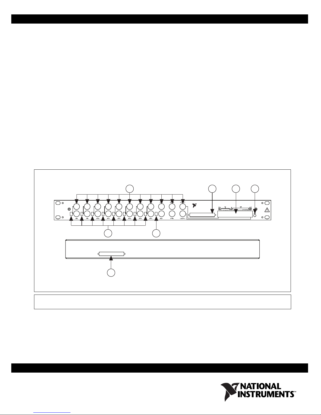
Figure 1 shows the BNC-2090A front panel and enclosure back.
SE
SE
DIFF
SE
DIFF
DIFFSEDIFFSEDIFFSEDIFFSEDIFFSEDIFF
1 BNC Connectors
2 68-Position Connectors
1 4
5
2
3 Spring Terminal Block
4+5V LED
Figure 1. BNC-2090A Front Panel and Back of Enclosure
2 3
NATIONAL
INSTRUMENTS
RSE
NRSE
BNC-2090A
6
5 SE/DIFF Switches
6 RSE/NRSE Switch
Page 2

Installing the BNC-2090A
To connect the BNC-2090A to your DAQ device, refer to Figure 2 as you
complete the following steps. Consult your computer user manual or
technical reference manual for specific instructions and warnings.
Note If you have not already installed your DAQ device, refer to the DAQ Getting Started
Guide for instructions.
4
3
N
ATIO
1
1 BNC-2090A
2 Shielded Cable
IN
S
N
T
A
R
L
U
M
B
E
N
N
C
T
-2
S
0
9
0
A
3 E/M Series DAQ Device
4 Personal Computer
Figure 2. Connecting the BNC-2090A to Your DAQ Device
1. Place the BNC-2090A near the host computer or mount the
BNC-2090A into a 19 inch rack. If you do not rack-mount the
accessory, attach the four adhesive rubber feet included in the
BNC-2090A kit to the bottom of the accessory.
2. Connect the BNC-2090A to the DAQ device using the front or rear
68-position connector, shown in Figure 1. Refer to Table 1 to verify
that you have the appropriate cable for your DAQ device.
2
BNC-2090A Quick Start Guide 2 ni.com
Page 3
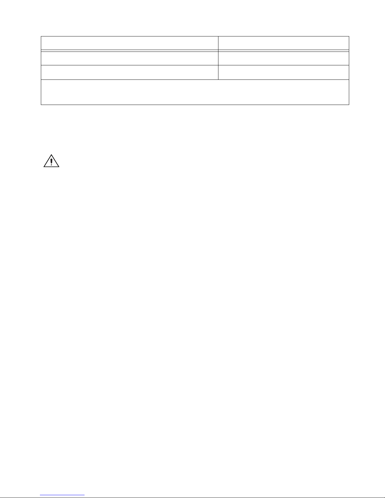
Table 1. BNC-2090A Cabling Options
DAQ Device Required Cable(s)
68-pin PCI, PCIe, PXI, or PXIe M Series
*
SHC68-68-EPM or RC68-68
68-pin PCI or PXI E Series SH68-68-EP or R6868
*
Two-connector M Series devices can be cabled to two BNC-2090A accessories with two cables.
Note: Refer to the BNC-2090A User Manual for information about other E/M Series device connections.
If the +5V LED does not light, check the cable connections.
When you have finished using the BNC-2090A, power off any external
signals connected to the BNC-2090A before you power off your computer.
Caution Do not connect input voltages greater than 42.4 V
/60 VDC to the BNC-2090A.
pk
The BNC-2090A is not designed for any input voltages greater than 42.4 V
even if a user-installed voltage divider reduces the voltage to within the input range of the
DAQ device. Input voltages greater than 42.4 V
/60 VDC can damage the BNC-2090A,
pk
all devices connected to it, and the host computer. Overvoltage can also cause an electric
shock hazard for the operator. National Instruments is not liable for damage or injury
resulting from such misuse.
/60 VDC,
pk
© National Instruments Corporation 3 BNC-2090A Quick Start Guide
Page 4

Connecting Differential Analog Input Signals
Complete the following steps to measure a differential (DIFF) analog input
signal.
1. Connect the BNC cable to one of the AI <0..7> BNC connectors on the
front panel.
Do not connect anything to the corresponding AI <8..15> BNC
connector below the AI <0..7> BNC connector you use.
2. Move the corresponding SE/DIFF switch to the DIFF position. On the
BNC-2090A front panel, a line indicates which SE/DIFF switch
corresponds to each AI <0..7> BNC connector.
3. Configure your software to measure this channel differentially.
Figure 3 shows how differential AI signals are routed to the DAQ device.
SE
DIFF
BNC-2090A
AI 0
AI 8
Do Not
Connect
Figure 3. Analog Input Differential Mode
NRSE
RSE
RSE/NRSE
Switch
Not Used
Cable
DAQ Device
AI 0
AI 8
BNC-2090A Quick Start Guide 4 ni.com
Page 5

Connecting Single-Ended Analog Input Signals
Complete the following steps to measure a single-ended (SE) analog input
signal.
1. Connect the BNC cable to one of the AI <0..15> BNC connectors on
the front panel.
2. Move the corresponding SE/DIFF switch to the SE position. On the
BNC-2090A front panel, a line indicates which SE/DIFF switch
corresponds to each AI <0..15> BNC connector.
3. Move the RSE/NRSE switch to select how the ground signal is routed.
All single-ended signals share the one RSE/NRSE switch. For more
information about non-referenced single-ended (NRSE) and
referenced single-ended (RSE) modes, refer to the E Series User
Manual or the M Series User Manual.
4. Configure your software to measure this channel in RSE or
NRSE mode.
Figure 4 shows how single-ended AI signals are routed to the DAQ device.
SE
DIFF
BNC-2090A
AI 0
NRSE
RSE
RSE/NRSE
AI 8
Figure 4. Analog Input Single-Ended Mode
Switch
Cable
DAQ Device
AI 0
AI SENSE
AI GND
AI 8
© National Instruments Corporation 5 BNC-2090A Quick Start Guide
Page 6

Connecting Analog Output, APFI, and PFI Signals
Use the BNC-2090A BNC connectors on the front panel to connect
AO <0..1>, APFI 0, and PFI 0 signals to your DAQ device. Refer to your
DAQ device documentation for information on the use of these signals.
Figure 5 shows how AO 0, AO 1, APFI 0, and PFI 0 signals are routed to
the DAQ device.
AO 0
AO 1
APFI 0
PFI 0
BNC-2090A
Cable
DAQ Device
AO 0
AO GND
AO 1
AI GND
APFI 0
D GND
Connecting Digital Signals
Use the BNC-2090A spring terminal block on the front panel to connect
digital signals to your DAQ device. Refer to your DAQ device
documentation for information on the use of these signals.
When connecting signals to the spring terminal blocks, you can use up to
20 AWG wire with the insulation stripped to 0.5 in.
BNC-2090A Quick Start Guide 6 ni.com
PFI 0
Figure 5. Analog Output, APFI 0, and PFI 0
Page 7

Using the USER 1 and USER 2 BNC Connectors
The USER 1 and USER 2 BNC connectors allow you to use a BNC
connector for a digital or timing I/O signal of your choice. The USER 1 and
USER 2 BNC connectors are routed (internal to the BNC-2090A) to the
USER1 and USER2 spring terminals, as shown in Figure 6.
USER 1 BNC
P0 PFI
6
5
DGND
+5V
7
1
243
56789
1011121314
D GND
USER1
DGND
01234
15
USER2
DGND
USER 2 BNC
BNC Cable
D GND
Figure 7 shows an example of how to use the USER <1..2> BNCs.
To access the PFI 5 signal from a BNC, connect USER1 on the spring
terminal block to PFI 5 with a wire.
USER 1 BNC
D GND
Internal Connection
USER1
DGND
01234
Internal
Connection
Screw Terminal Block
Figure 6. USER <1..2> BNC Connections
P0 PFI
6
5
Wire
DGND
+5V
7
1
243
56789
Screw Terminal Block
1011121314
15
USER2
DGND
PFI 5
Signal
© National Instruments Corporation 7 BNC-2090A Quick Start Guide
Figure 7. Connecting PFI 5 to USER 1 BNC
Page 8

Where to Go from Here
Refer to the BNC-2090A User Manual for information about the following
subjects:
• Detailed installation instructions
• In-depth signal information
• Using the BNC-2090A with DAQCard and 100-pin E Series devices
and USB Mass Termination M Series devices
• Changing the shield ground jumper setting
• Installing signal conditioning components
• BNC-2090A specifications
You can find the BNC-2090A User Manual on
ni.com/manuals.
National Instruments, NI, ni.com, and LabVIEW are trademarks of National Instruments Corporation.
Refer to the Terms of Use section on ni.com/legal for more information about National
Instruments trademarks. Other product and company names mentioned herein are trademarks or trade
names of their respective companies. For patents covering National Instruments products, refer to the
appropriate location: Help»Patents in your software, the patents.txt file on your CD, or
ni.com/patents.
© 2006 National Instruments Corporation. All rights reserved.
371877A-01 Dec06
 Loading...