

Page 1

NI MATRIXx
AutoCodeTM Reference
AutoCode Reference
TM
April 2007
370768C-01
Page 2

Support
Worldwide Technical Support and Product Information
ni.com
National Instruments Corporate Headquarters
11500 North Mopac Expressway Austin, Texas 78759-3504 USA Tel: 512 683 0100
Worldwide Offices
Australia 1800 300 800, Austria 43 662 457990-0, Belgium 32 (0) 2 757 0020, Brazil 55 11 3262 3599,
Canada 800 433 3488, China 86 21 5050 9800, Czech Republic 420 224 235 774, Denmark 45 45 76 26 00,
Finland 385 (0) 9 725 72511, France 33 (0) 1 48 14 24 24, Germany 49 89 7413130, India 91 80 41190000,
Israel 972 3 6393737, Italy 39 02 413091, Japan 81 3 5472 2970, Korea 82 02 3451 3400,
Lebanon 961 (0) 1 33 28 28, Malaysia 1800 887710, Mexico 01 800 010 0793, Netherlands 31 (0) 348 433 466,
New Zealand 0800 553 322, Norway 47 (0) 66 90 76 60, Poland 48 22 3390150, Portugal 351 210 311 210,
Russia 7 495 783 6851, Singapore 1800 226 5886, Slovenia 386 3 425 42 00, South Africa 27 0 11 805 8197,
Spain 34 91 640 0085, Sweden 46 (0) 8 587 895 00, Switzerland 41 56 2005151, Taiwan 886 02 2377 2222,
Thailand 662 278 6777, Turkey 90 212 279 3031, United Kingdom 44 (0) 1635 523545
For further support information, refer to the Technical Support and Professional Services appendix. To comment
on National Instruments documentation, refer to the National Instruments Web site at ni.com/info and enter
the info code feedback.
© 2007 National Instruments Corporation. All rights reserved.
Page 3

Important Information
Warranty
The media on which you receive National Instruments software are warranted not to fail to execute programming instructions, due to defects
in materials and workmanship, for a period of 90 days from date of shipment, as evidenced by receipts or other documentation. National
Instruments will, at its option, repair or replace software media that do not execute programming instructions if National Instruments receives
notice of such defects during the warranty period. National Instruments does not warrant that the operation of the software shall be
uninterrupted or error free.
A Return Material Authorization (RMA) number must be obtained from the factory and clearly marked on the outside of the package before any
equipment will be accepted for warranty work. National Instruments will pay the shipping costs of returning to the owner parts which are covered by
warranty.
National Instruments believes that the information in this document is accurate. The document has been carefully reviewed for technical accuracy. In
the event that technical or typographical errors exist, National Instruments reserves the right to make changes to subsequent editions of this document
without prior notice to holders of this edition. The reader should consult National Instruments if errors are suspected. In no event shall National
Instruments be liable for any damages arising out of or related to this document or the information contained in it.
E
XCEPT AS SPECIFIED HEREIN, NATIONAL INSTRUMENTS MAKES NO WARRANTIES, EXPRESS OR IMPLIED, AND SPECIFICALLY DISCLAIMS ANY WARRANTY OF
MERCHANTABILITY OR FITNESS FOR A PARTICULAR PURPOSE. CUSTOMER’S RIGHT TO RECOVER DAMAGES CAUSED BY FAULT OR NEGLIGENCE ON THE PART OF NATIONAL
I
NSTRUMENTS SHALL BE LIMITED TO THE AMOUNT THERETOFORE PAID BY THE CUSTOMER. NATIONAL INSTRUMENTS WILL NOT BE LIABLE FOR DAMAGES RESULTING
FROM LOSS OF DATA, PROFITS, USE OF PRODUCTS, OR INCIDENTAL OR CONSEQUENTIAL DAMAGES, EVEN IF ADVISED OF THE POSSIBILITY THEREOF. This limitation of
the liability of National Instruments will apply regardless of the form of action, whether in contract or tort, including negligence. Any action against
National Instruments must be brought within one year after the cause of action accrues. National Instruments shall not be liable for any delay in
performance due to causes beyond its reasonable control. The warranty provided herein does not cover damages, defects, malfunctions, or service
failures caused by owner’s failure to follow the National Instruments installation, operation, or maintenance instructions; owner’s modification of the
product; owner’s abuse, misuse, or negligent acts; and power failure or surges, fire, flood, accident, actions of third parties, or other events outside
reasonable control.
Copyright
Under the copyright laws, this publication may not be reproduced or transmitted in any form, electronic or mechanical, including photocopying,
recording, storing in an information retrieval system, or translating, in whole or in part, without the prior written consent of National
Instruments Corporation.
National Instruments respects the intellectual property of others, and we ask our users to do the same. NI software is protected by copyright and other
intellectual property laws. Where NI software may be used to reproduce software or other materials belonging to others, you may use NI software only
to reproduce materials that you may reproduce in accordance with the terms of any applicable license or other legal restriction.
Trademarks
AutoCode™, DocumentIt™, MATRIXx™, National Instruments™, NI™, ni.com™, SystemBuild™, and Xmath™ are trademarks of
National Instruments Corporation. Refer to the Terms of Use section on ni.com/legal for more information about National Instruments
trademarks.
Other product and company names mentioned herein are trademarks or trade names of their respective companies.
Members of the National Instruments Alliance Partner Program are business entities independent from National Instruments and have no agency,
partnership, or joint-venture relationship with National Instruments.
Patents
For patents covering National Instruments products, refer to the appropriate location: Help»Patents in your software, the patents.txt file
on your CD, or
ni.com/patents.
WARNING REGARDING USE OF NATIONAL INSTRUMENTS PRODUCTS
(1) NATIONAL INSTRUMENTS PRODUCTS ARE NOT DESIGNED WITH COMPONENTS AND TESTING FOR A LEVEL OF
RELIABILITY SUITABLE FOR USE IN OR IN CONNECTION WITH SURGICAL IMPLANTS OR AS CRITICAL COMPONENTS IN
ANY LIFE SUPPORT SYSTEMS WHOSE FAILURE TO PERFORM CAN REASONABLY BE EXPECTED TO CAUSE SIGNIFICANT
INJURY TO A HUMAN.
(2) IN ANY APPLICATION, INCLUDING THE ABOVE, RELIABILITY OF OPERATION OF THE SOFTWARE PRODUCTS CAN BE
IMPAIRED BY ADVERSE FACTORS, INCLUDING BUT NOT LIMITED TO FLUCTUATIONS IN ELECTRICAL POWER SUPPLY,
COMPUTER HARDWARE MALFUNCTIONS, COMPUTER OPERATING SYSTEM SOFTWARE FITNESS, FITNESS OF COMPILERS
AND DEVELOPMENT SOFTWARE USED TO DEVELOP AN APPLICATION, INSTALLATION ERRORS, SOFTWARE AND HARDWARE
COMPATIBILITY PROBLEMS, MALFUNCTIONS OR FAILURES OF ELECTRONIC MONITORING OR CONTROL DEVICES,
TRANSIENT FAILURES OF ELECTRONIC SYSTEMS (HARDWARE AND/OR SOFTWARE), UNANTICIPATED USES OR MISUSES, OR
ERRORS ON THE PART OF THE USER OR APPLICATIONS DESIGNER (ADVERSE FACTORS SUCH AS THESE ARE HEREAFTER
COLLECTIVELY TERMED “SYSTEM FAILURES”). ANY APPLICATION WHERE A SYSTEM FAILURE WOULD CREATE A RISK OF
HARM TO PROPERTY OR PERSONS (INCLUDING THE RISK OF BODILY INJURY AND DEATH) SHOULD NOT BE RELIANT SOLELY
UPON ONE FORM OF ELECTRONIC SYSTEM DUE TO THE RISK OF SYSTEM FAILURE. TO AVOID DAMAGE, INJURY, OR DEATH,
THE USER OR APPLICATION DESIGNER MUST TAKE REASONABLY PRUDENT STEPS TO PROTECT AGAINST SYSTEM FAILURES,
INCLUDING BUT NOT LIMITED TO BACK-UP OR SHUT DOWN MECHANISMS. BECAUSE EACH END-USER SYSTEM IS
CUSTOMIZED AND DIFFERS FROM NATIONAL INSTRUMENTS' TESTING PLATFORMS AND BECAUSE A USER OR APPLICATION
DESIGNER MAY USE NATIONAL INSTRUMENTS PRODUCTS IN COMBINATION WITH OTHER PRODUCTS IN A MANNER NOT
EVALUATED OR CONTEMPLATED BY NATIONAL INSTRUMENTS, THE USER OR APPLICATION DESIGNER IS ULTIMATELY
RESPONSIBLE FOR VERIFYING AND VALIDATING THE SUITABILITY OF NATIONAL INSTRUMENTS PRODUCTS WHENEVER
NATIONAL INSTRUMENTS PRODUCTS ARE INCORPORATED IN A SYSTEM OR APPLICATION, INCLUDING, WITHOUT
LIMITATION, THE APPROPRIATE DESIGN, PROCESS AND SAFETY LEVEL OF SUCH SYSTEM OR APPLICATION.
Page 4

Conventions
The following conventions are used in this manual:
<> Angle brackets that contain numbers separated by an ellipsis represent a
range of values associated with a bit or signal name—for example,
DIO<3..0>.
» The » symbol leads you through nested menu items and dialog box options
to a final action. The sequence File»Page Setup»Options directs you to
pull down the File menu, select the Page Setup item, and select Options
from the last dialog box.
This icon denotes a note, which alerts you to important information.
This icon denotes a caution, which advises you of precautions to take to
avoid injury, data loss, or a system crash.
bold Bold text denotes items that you must select or click in the software, such
as menu items and dialog box options. Bold text also denotes parameter
names.
italic Italic text denotes variables, emphasis, a cross-reference, or an introduction
to a key concept. Italic text also denotes text that is a placeholder for a word
or value that you must supply.
monospace Text in this font denotes text or characters that you should enter from the
keyboard, sections of code, programming examples, and syntax examples.
This font is also used for the proper names of disk drives, paths, directories,
programs, subprograms, subroutines, device names, functions, operations,
variables, filenames, and extensions.
monospace bold Bold text in this font denotes the messages and responses that the computer
automatically prints to the screen. This font also emphasizes lines of code
that are different from the other examples.
monospace italic
Italic text in this font denotes text that is a placeholder for a word or value
that you must supply.
Page 5

Contents
Chapter 1
Introduction
Manual Organization .....................................................................................................1-1
General Information.......................................................................................................1-2
Configuration File..........................................................................................................1-2
Language-Specific Information .....................................................................................1-2
Structure and Content of the Generated Code ...............................................................1-3
Using MATRIXx Help ..................................................................................................1-3
Additional Netscape Information ....................................................................1-3
Related Publications ......................................................................................................1-4
Chapter 2
C Language Reference
Stand-Alone Simulation.................................................................................................2-1
Compiling on Various Supported Platforms ...................................................2-1
Stand-Alone Library ......................................................................................................2-2
System-Specific Files ......................................................................................2-2
Target-Specific Utilities ..................................................................................2-5
enable( ), disable( ), and background( ) Functions ...........................2-6
error( ) and fatalerr( ) Functions .......................................................2-6
fatalerr( ): Stand-Alone Utilities Detected Errors .............................2-7
ERROR: Conditions Detected in the Generated Code......................2-8
Implementation_Initialize( ) Function ..............................................2-9
Implementation_Terminate( ) Function............................................2-9
External_Input ( ) Function...............................................................2-10
External_Output ( ) Function ............................................................2-10
UserCode Blocks ...........................................................................................................2-10
Linking Handwritten UCBs with AutoCode Applications..............................2-11
Implementing Handwritten UCBs ....................................................2-13
Linking Handwritten UCBs (for AutoCode) with SystemBuild .....................2-16
Variable Interface UCB...................................................................................2-18
Interface Ordering .............................................................................2-18
Inputs and Outputs ............................................................................2-18
Function Prototype............................................................................2-19
Linking a Variable Interface UCB with the Simulator .....................2-20
Procedure SuperBlocks..................................................................................................2-20
Generating Reusable Procedures.....................................................................2-20
Linking Procedures with the SystemBuild Simulator .....................................2-20
© National Instruments Corporation v AutoCode Reference
Page 6

Contents
Linking Procedures with Real-Time Applications or Simulator .................... 2-22
Invoking Generated Procedures Directly.......................................... 2-22
Invoking Procedures Using Generated UCB Wrapper Function...... 2-24
Invoking Procedures Using Generated Subsystem Function ........... 2-25
C Fixed-Point Arithmetic .............................................................................................. 2-26
Fixed-Point AutoCode/C Implementation ...................................................... 2-26
Generated Code with Fixed-Point Variables .................................................. 2-28
Fixed-Point Data Types .................................................................................. 2-28
User Types ...................................................................................................... 2-30
Overflow Protection........................................................................................ 2-31
Stand-Alone Files............................................................................................ 2-31
Macro Interface ...............................................................................................2-32
Function Interface ........................................................................................... 2-33
Fixed-Point Conversion and Arithmetic Macros ............................................ 2-35
Conversion Macros...........................................................................2-35
Arithmetic Macros............................................................................ 2-38
Implementation of the Addition and Subtraction Macros ................ 2-40
Selecting Wordsize Extension in the Preprocessor Macro ............... 2-42
32-Bit Multiplication and Division Macros...................................... 2-42
32-Bit Multiplication ........................................................................ 2-42
32-Bit Division ................................................................................. 2-43
16-Bit by 8-Bit Division ................................................................... 2-43
32-Bit by 16-Bit Division ................................................................. 2-43
Fixed-Point Relational Macros ....................................................................... 2-44
Some Relevant Issues...................................................................................... 2-45
Chapter 3
Ada Language Reference
Stand-Alone Simulation ................................................................................................ 3-1
Supported Ada Compilers for the Stand-Alone Library ................................. 3-1
Supplied Templates ....................................................................................................... 3-2
ada_rt.tpl Template ......................................................................................... 3-2
ada_sim.tpl Template ...................................................................................... 3-2
ada_fxpt_sys.tpl Template .............................................................................. 3-2
ada_fxpt_sub.tpl Template.............................................................................. 3-2
Stand-Alone Library...................................................................................................... 3-3
System-Specific Files...................................................................................... 3-3
Data Types........................................................................................ 3-5
Target-Specific Utilities .................................................................................. 3-6
Enable( ), Disable( ), and Background( ) Procedures....................... 3-7
Error Procedure( ) Procedure............................................................3-7
Implementation_Initialize( ) Procedure............................................ 3-8
Implementation_Terminate( ) Procedure.......................................... 3-10
AutoCode Reference vi ni.com
Page 7

Contents
External_Input ( ) Procedure.............................................................3-10
External_Output( ) Procedure ...........................................................3-11
UserCode Blocks ...........................................................................................................3-11
Linking Handwritten UCBs with AutoCode Applications..............................3-11
Calling UCBs...................................................................................................3-12
Procedure SuperBlocks..................................................................................................3-14
Generating Reusable Procedures.....................................................................3-14
Linking Procedures with Real-Time Applications or Simulator.....................3-14
Ada Fixed-Point Arithmetic...........................................................................................3-16
How to Generate Real-Time Code ..................................................................3-16
Fixed-Point AutoCode/Ada Architecture ........................................................3-16
Fixed-Point Data Types ....................................................................3-17
Generic Functions .............................................................................3-17
Instantiated Functions .......................................................................3-17
Package Dependencies......................................................................3-18
Generated Code with Fixed-Point Variables...................................................3-19
User Types.......................................................................................................3-19
System-Level Parameters to Generate User Types...........................3-20
Overflow Protection ........................................................................................3-20
Stand-Alone Files ............................................................................................3-21
Compilation Example......................................................................................3-21
Fixed-Point Type Declarations........................................................................3-23
Generic Functions............................................................................................3-23
Bit-Wise Functions..........................................................................................3-26
Instantiated Functions Package .......................................................................3-26
Operator Instantiations......................................................................3-26
Conversion Function Instantiations ..................................................3-27
Sample Package ................................................................................3-28
Addition and Subtraction Functions ................................................................3-29
Multiplication and Division Functions ............................................................3-31
32-Bit Multiplication.........................................................................3-31
32-Bit Division..................................................................................3-31
Conversion Functions......................................................................................3-31
Language-Defined Conversion .........................................................3-32
Truncation Conversion...................................................................... 3-32
Explicit Rounding Conversion..........................................................3-32
Using System-Level Parameters to Generate Instantiations ...........................3-33
Using Subsystem-Level Parameters to Generate Instantiations......................3-33
System Scope Operators and Conversions........................................3-34
Known Ada Compiler Problems .....................................................................3-35
Comparing Results to SystemBuild’s Simulator.............................................3-35
No-Op Conversion Function ...........................................................................3-36
© National Instruments Corporation vii AutoCode Reference
Page 8

Contents
Chapter 4
Generating Code for Real-Time Operating Systems
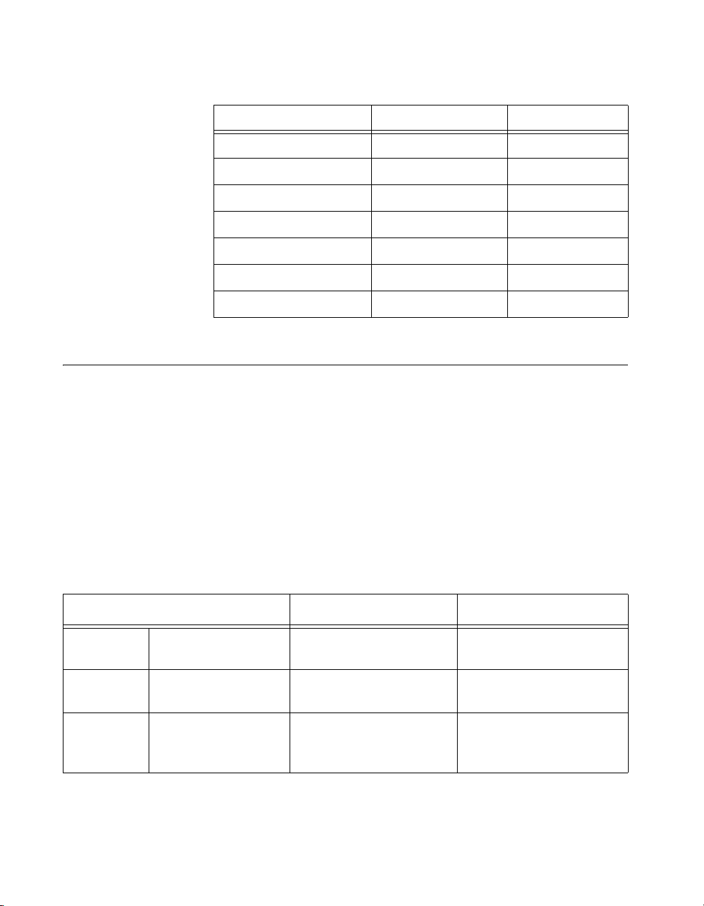
Real-Time Operating System Configuration File.......................................................... 4-1
Configuration Items ........................................................................................ 4-2
Table Syntax ................................................................................................... 4-2
Table Naming Convention................................................................ 4-3
Table Column Contents .................................................................... 4-3
Table Orderings ................................................................................ 4-3
File Comments.................................................................................. 4-3
RTOS Configuration File Contents................................................................. 4-3
Processors Table ............................................................................... 4-3
Scheduler Priority Table................................................................... 4-4
Subsystem Table............................................................................... 4-4
Interrupt Procedure SuperBlock Table ............................................. 4-5
Background Procedure SuperBlock Table........................................ 4-6
Startup Procedure SuperBlock Table ............................................... 4-7
Processor IP Name Table ................................................................. 4-7
Version Table ................................................................................... 4-8
Using the Configuration File...........................................................................4-8
Chapter 5
Generated Code Architecture
Symbolic Name Creation .............................................................................................. 5-1
Default Names................................................................................................. 5-1
Signal Naming................................................................................................. 5-2
Duplicate Names ............................................................................................. 5-2
Selection of a Signal Name............................................................................. 5-2
Subsystem and Procedure Boundaries.............................................. 5-2
Typecheck Feature and Data Types ................................................................ 5-2
Global Storage ............................................................................................................... 5-3
Percent vars (%var)......................................................................................... 5-3
Global Variable Blocks................................................................................... 5-3
Sequencing Variable Blocks............................................................. 5-3
Global Variable Block and %var Equivalence ................................. 5-4
Optimization for Read-From Variable Blocks ................................. 5-4
Global Scope Signal Capability ...................................................................... 5-4
Subsystems .................................................................................................................... 5-5
Discrete and Continuous SuperBlocks Versus Subsystems............................ 5-5
Top-Level SuperBlock ..................................................................... 5-6
Block Ordering................................................................................................ 5-6
Interface Layers............................................................................................... 5-6
Scheduler External Interface Layer................................................................. 5-7
AutoCode Reference viii ni.com
Page 9

Contents
System External Interface Layer .....................................................................5-7
Discrete Subsystem Interface Layer................................................................5-8
Single-Rate System ...........................................................................5-8
Multi-Rate System ............................................................................5-8
Sample and Hold...............................................................................5-8
Static Data Within Subsystems .......................................................................5-9
iinfo ...................................................................................................5-9
R_P and I_P ......................................................................................5-9
State Data ..........................................................................................5-9
Procedure Data..................................................................................5-10
Pre-init Phase...................................................................................................5-10
Init, Output, and State Phases..........................................................................5-10
Copy Back and Duplicates ..............................................................................5-10
Error Handling.................................................................................................5-11
Standard Procedures ......................................................................................................5-11
Structure-Based Interface ................................................................................5-11
Unrolled Interface............................................................................................5-12
Phases and Error Handling ..............................................................................5-12
Referenced Percent Variables..........................................................................5-12
Procedure Arguments ......................................................................................5-15
U, Y, S, and I.....................................................................................5-15
Extended Procedure Information Structure .....................................................5-18
Caller Identification ..........................................................................5-18
Compatibility Issues..........................................................................5-19
Macro Procedure............................................................................................................5-20
Interface...........................................................................................................5-20
Asynchronous Procedures..............................................................................................5-21
Interrupt ...........................................................................................................5-21
Background......................................................................................................5-21
Startup..............................................................................................................5-21
Changing %var Values During Startup.............................................5-22
Condition Block.............................................................................................................5-22
Default Mode...................................................................................................5-22
No-Default Mode.............................................................................................5-22
Sequential Mode..............................................................................................5-22
BlockScript Block..........................................................................................................5-22
Inputs and Outputs...........................................................................................5-23
Environment Variables....................................................................................5-24
Local Variables................................................................................................5-24
Init, Output, and State Phases..........................................................................5-25
Default Phase ....................................................................................5-26
© National Instruments Corporation ix AutoCode Reference
Page 10

Contents
States ............................................................................................................... 5-26
Local Variables and Phases .............................................................. 5-27
Discrete Semantics ........................................................................... 5-27
Continuous Semantics ...................................................................... 5-29
Looping Concepts ........................................................................................... 5-29
Terminology ..................................................................................... 5-29
Loops and Scalar Code ..................................................................... 5-29
Rolling Loops with Scalar Code Generation .................................... 5-30
Vectorized Code ............................................................................... 5-31
Types of Loops ................................................................................. 5-31
Examples of Rolled and Unrolled Loops ......................................... 5-32
Parameters....................................................................................................... 5-33
Using Parameters Instead of States in a Discrete Model.................. 5-33
Optimizations .................................................................................................. 5-35
Constant Propagation/Hard-Coding ................................................. 5-35
Dead Code Elimination .................................................................... 5-35
Implicit Type Conversion................................................................. 5-36
Special Directives ........................................................................................... 5-36
UserCode Block............................................................................................................. 5-37
Phases of the UCB .......................................................................................... 5-37
Indirect Terms ................................................................................................. 5-37
Parameterized UCB Callout............................................................................ 5-38
Software Constructs....................................................................................................... 5-39
IfThenElse Block ............................................................................................ 5-39
WHILE Block ................................................................................................. 5-39
BREAK Block................................................................................................. 5-40
CONTINUE Block..........................................................................................5-40
Local Variable Block ...................................................................................... 5-40
Sequencer Block ............................................................................................. 5-41
Difference Between Local and Global Variable Blocks ............................................... 5-41
Scope...............................................................................................................5-41
Lifetime........................................................................................................... 5-41
Continuous Subsystem .................................................................................................. 5-41
Explicit Phases ................................................................................................5-42
Integrator......................................................................................................... 5-42
Limitations ...................................................................................................... 5-42
Multiprocessor Code Generation................................................................................... 5-43
Shared Memory Architecture.......................................................................... 5-43
Distributed Memory Architecture................................................................... 5-44
Shared Memory Callouts ................................................................................ 5-44
Callout Naming Convention ............................................................. 5-44
Mapping Command Options........................................................................... 5-45
Fixed-Point Support for Multiprocessor AutoCode ........................................ 5-45
AutoCode Reference x ni.com
Page 11

Definitions and Conventions ...........................................................................5-45
Shared Memory Fixed-Point Callouts in AutoCode/C .....................5-46
Shared Variable Block Support.......................................................................5-47
Shared Memory Callout Option........................................................5-50
Global Variable Block Callouts.......................................................................5-51
Callout Pairs......................................................................................5-51
Non-Shared (Local) Global Variable Blocks....................................5-51
Shared Global Variable Blocks.........................................................5-53
Chapter 6
Vectorized Code Generation
Introduction....................................................................................................................6-1
How Code Is Generated...................................................................................6-1
Scalar Gain Block Example ..............................................................6-2
Vectorized Gain Block Example.......................................................6-3
Array Subscripts................................................................................6-4
Signal Connectivity .........................................................................................6-5
Block Outputs ...................................................................................6-5
Block Inputs ......................................................................................6-5
Vectorization Modes......................................................................................................6-7
Maximal Vectorization....................................................................................6-7
Mixed Vectorization........................................................................................6-7
Vector Labels and Names .................................................................6-8
Example...........................................................................................................6-8
Vectorization Features ...................................................................................................6-14
Multiple Arrays within a Block.......................................................................6-15
Split-Merge Inefficiency .................................................................................6-17
Split Vector .......................................................................................6-17
Merge ................................................................................................6-19
External Outputs..............................................................................................6-21
Copy-Back ........................................................................................6-21
Eliminating Copy-Back.....................................................................6-23
Other Copy-Back Scenarios..............................................................6-23
Vectorized Standard Procedure Interface........................................................6-23
Ada Array Aggregates and Slices....................................................................6-25
Vectorization of the BlockScript Block.........................................................................6-27
Matrix Outputs...............................................................................................................6-28
Contents
© National Instruments Corporation xi AutoCode Reference
Page 12

Contents
Chapter 7
Code Optimization
Read from Variable Blocks ........................................................................................... 7-1
Restart Capability .......................................................................................................... 7-5
Merging INIT Sections..................................................................................................7-8
Reuse of Temporary Block Outputs .............................................................................. 7-11
Reuse Temporaries as Specified ..................................................................... 7-11
Maximal Reuse of Temporaries...................................................................... 7-11
Constant Propagation.....................................................................................................7-13
Optimizing with Matrix Blocks..................................................................................... 7-16
Optimizing with Constant Blocks ................................................................... 7-16
Optimizing with Callout Blocks ..................................................................... 7-17
Optimizing with Inverse Blocks ....................................................... 7-17
Optimizing with Division Blocks ..................................................... 7-17
Summary........................................................................................................................ 7-19
Chapter 8
AutoCode Sim Cdelay Scheduler
Introduction ................................................................................................................... 8-1
Task Posting Policies..................................................................................................... 8-2
Standard AutoCode Scheduler ......................................................................................8-3
Scheduler Pipeline........................................................................................... 8-5
Managing DataStores in the Scheduler........................................................... 8-7
Sim Cdelay Scheduler ................................................................................................... 8-9
State Transition Diagrams of Tasks under Sim Cdelay................................................. 8-10
Implementing the Sim Cdelay AutoCode Scheduler..................................................... 8-12
Implementation Details ................................................................................... 8-12
DataStore Priority Problem............................................................................. 8-13
Using the Sim Cdelay Scheduler................................................................................... 8-14
Template Configuration for Enhanced Performance..................................................... 8-15
Shortcomings of the Sim Cdelay Scheduler.................................................................. 8-16
Chapter 9
Global Scope Signals and Parameterless Procedures
Introduction ................................................................................................................... 9-1
Data Monitoring/Injection .............................................................................................9-2
Specifying Monitored Signals......................................................................... 9-2
Generating Code for Monitored Signals ......................................................... 9-3
Limitations ...................................................................................................... 9-4
Unsupported Blocks ......................................................................... 9-4
Connection to External Output ......................................................... 9-4
AutoCode Reference xii ni.com
Page 13

Contents
Variable Block Aliasing....................................................................9-4
Monitored Signals within a Procedure SuperBlock ..........................9-4
Monitoring Procedure External Outputs ...........................................9-4
Parameterless Procedure ................................................................................................9-5
Specifying Parameterless Procedure Interface ................................................9-5
Input Specification ............................................................................9-5
Output Specification .........................................................................9-6
Using a Parameterless Procedure ....................................................................9-6
Global-to-Global Input Connection ..................................................9-6
Global Output Connection ................................................................9-6
Condition Block Code Generation ..................................................................9-7
Reusing a Parameterless Procedure.................................................................9-7
Generating Code for Parameterless Procedures ..............................................9-7
Issues and Limitations .....................................................................................9-8
Communication Between Subsystems ..............................................9-8
Variable Blocks Versus Global Scope ..............................................9-8
SystemBuild Simulator .....................................................................9-8
Connection to External Output .........................................................9-9
Recommendations ...........................................................................................9-9
Naming Convention ..........................................................................9-9
Model Documentation.......................................................................9-9
Explicit Sequencing ..........................................................................9-9
Analyzer and AutoCode Warnings ...................................................9-10
Changing Scope Class.......................................................................9-10
Command Options .........................................................................................................9-10
Appendix A
Technical Support and Professional Services
Index
© National Instruments Corporation xiii AutoCode Reference
Page 14

Introduction
This manual provides reference material for using AutoCode to write
production quality code using graphical tools. Together with the AutoCode
User Guide and the Template Programming Language User Guide,
AutoCode documentation describes how to generate robust, high-quality,
real-time C or Ada source code from SystemBuild block diagrams.
Manual Organization
This manual includes the following chapters:
• Chapter 1, Introduction, provides an overview of the rapid prototyping
concept, the automatic code generation process, and the nature of
real-time generated code.
• Chapter 2, C Language Reference, discusses files used to interface
AutoCode and the generated C code to your specific platform and
target processor, and target-specific utilities needed for simulation and
testing.
• Chapter 3, Ada Language Reference, discusses files used to interface
AutoCode and the generated Ada code to your specific platform and
target processor, and target-specific utilities needed for simulation and
testing.
• Chapter 4, Generating Code for Real-Time Operating Systems,
describes the RTOS configuration file and functionality provided for
generating code for real-time operating systems.
• Chapter 5, Generated Code Architecture, supplies more details about
the content and framework of the generated code. This includes
storage usage, various procedures, specialized blocks, and subsystems.
• Chapter 6, Vectorized Code Generation, discusses various ways to
generate vectorized code. This includes describing the options
available, design guidelines, and implementation details about the
vectorized code.
• Chapter 7, Code Optimization, discusses how to optimize the
generated code. This includes explaining the details of generating
production quality code for micro controller-based applications.
1
© National Instruments Corporation 1-1 AutoCode Reference
Page 15

Chapter 1 Introduction
• Chapter 8, AutoCode Sim Cdelay Scheduler, discusses the Sim Cdelay
low-latency scheduler.
• Chapter 9, Global Scope Signals and Parameterless Procedures,
discusses additional signals and procedures.
This guide also has an Index.
General Information
As an integral part of the rapid prototyping concept, AutoCode lets you
generate high-level language code from a SystemBuild block diagram
model quickly, automatically, and without programming skills. The
AutoCode User Guide describes the processes for generating code,
including the parameters that you must use. This manual provides details
of how AutoCode actually works, so that you will have an idea of what to
expect from AutoCode if you attempt to modify the generation of code.
Configuration File
The configuration file is a text file containing tables of information related
to the generated source code components of a model, like subsystems and
nonscheduled procedure SuperBlocks. Each table contains configuration
information about its respective component. Various configuration files are
supplied with AutoCode, including one for Real-Time Operating Systems
(RTOS) as described in Chapter 4, Generating Code for Real-Time
Operating Systems. For additional configuration information, refer to the
AutoCode User Guide.
Language-Specific Information
This manual describes some of the details of AutoCode operation for both
the C and Ada languages.
Specific topics include the following:
• Stand-alone (
• Fixed-point code generation
• UserCode Blocks (UCBs)
• Macro Procedure Blocks
• Procedure SuperBlocks
AutoCode Reference 1-2 ni.com
sa) files
Page 16

Structure and Content of the Generated Code
This reference includes detailed descriptions about what is generated for
many of the blocks used within a model. Also, the framework of the
generated code is discussed to show how all of the pieces work together to
form an executable simulation. This discussion is only relevant to those
designers who are either writing their own templates or who are striving to
optimize the generated code.
Topics include the following:
• Generating code for use within real-time operating systems
• Code architecture
• Vectorized code generation
Using MATRIXx Help
MATRIXx 7.x provides a hypertext markup language (HTML) help
system. The MATRIXx Help is a self-contained system with multiple
hypertext links from one component to another. This help, augmented by
online and printed manuals, covers most MATRIXx topics except for
installation.
Chapter 1 Introduction
The MATRIXx Help runs on Netscape. The MATRIXx CD-ROM includes
the supported version. On UNIX systems, an OEM version of Navigator is
automatically included in the MATRIXx installation. On PCs, Netscape
must be installed independently using the Netscape installation procedure
included on the MATRIXx CD.
Additional Netscape Information
For more information on Netscape products, visit the Netscape Web site at
http://home.netscape.com.
© National Instruments Corporation 1-3 AutoCode Reference
Page 17

Chapter 1 Introduction
Related Publications
National Instruments provides a complete library of publications to support
its products. In addition to this guide, publications that you may find
particularly useful when using AutoCode include the following:
• AutoCode User Guide
• Template Programming Language User Guide
• Xmath User Guide
• SystemBuild User Guide
• BlockScript User Guide
• DocumentIt User Guide
For additional documentation, refer to the MATRIXx Help or visit the
National Instruments Web site at
ni.com/manuals.
AutoCode Reference 1-4 ni.com
Page 18

C Language Reference
This chapter discusses files used to interface AutoCode and the generated
C code to your specific platform and target processor. This chapter also
describes target-specific utilities needed for simulation and testing.
Stand-Alone Simulation
The template provided for C code generation produces code that, when
compiled and linked with stand-alone files, forms a stand-alone simulation.
This simulation can be executed with MATRIXx-style data as input, and
produces results that can be loaded back into Xmath for analysis. You must
compile the generated code along with the stand-alone library to produce
the simulation executable.
Chapter 2, Using AutoCode, of the AutoCode User Guide describes how to
compile the code and stand-alone library, generate sample input data, and
load the data into Xmath for analysis.
Compiling on Various Supported Platforms
The generated code usually includes platform-specific code. Most of this
code is not generated by AutoCode; rather, that code exists in the template.
Also, the stand-alone library has platform-specific code to deal with file I/O
and floating-point numerics. You must compile the generated code and the
stand-alone library with a defined preprocessor symbol appropriate for
your platform (refer to Table 2-1). For example, on the Solaris platform,
the compile statement is similar to:
2
% acc -DSOLARIS -o simulation simmodel.c sa_*.o -lm
Note
This example assumes the stand-alone library was compiled into separate object
files into the current working directory and that the stand-alone header files also exist in
the current working directory.
© National Instruments Corporation 2-1 AutoCode Reference
Page 19
Chapter 2 C Language Reference
Table 2-1. Recognized C Preprocessor Defines for Supported Platforms
Platform Preprocessor Define Compiler Switch
AIX (IBM UNIX) IBM
Compaq Tru64 5.0 OSF1
HPUX (700 series) HP700
HPUX (other than 700) HP
SGI IRIX SGI
Sun Solaris 2.x SOLARIS
Windows 2000/NT/9x MSWIN32
Stand-Alone Library
This section describes the system-specific and target-specific stand-alone
(
sa) files supplied with your system.
System-Specific Files
National Instruments furnishes files to interface AutoCode and the
generated code to your development platform (AIX, Compaq, HP,
SGI, Solaris, Windows) and to the target processor in your test bed or
rapid-prototyping system. Both header (
source files are provided in your
the distribution directories and files are shown in Table 2-2.
-DIBM
-DOSF1
-DHP700
-DHP
-DSGI
-DSOLARIS
-DMSWIN32
.h extension) and C (.c extension)
src distribution directory. The names of
Table 2-2. Distribution Directories and Files
Platform UNIX Windows
Top-Level
Environment variable:
$MTXHOME %MTXHOME%
Directory
Executables Directory:
Executable:
Utilities Directory:
Files:
Script:
AutoCode Reference 2-2 ni.com
$MTXHOME/bin
autostar
$CASE/ACC/src
sa_*.c, sa_*.h
compile_c_sa.sh
%MTXHOME%\bin
autostar
%CASE%\ACC\src
sa_*.c, sa_*.h
compile_c_sa.bat
Page 20
Chapter 2 C Language Reference
Table 2-2. Distribution Directories and Files (Continued)
Platform UNIX Windows
Templates Directory:
Templates:
Direct Access
Templates:
Demos Directory:
Note If you use the fuzzy logic block in your model, the sa_fuzz.c and sa_fuzzy.h
files must be available locally. Use this file only when linking an AutoCode UCB back into
SystemBuild. Also,
into the stand-alone simulation if your SystemBuild model includes UCBs. Refer to the
Linking Handwritten UCBs (for AutoCode) with SystemBuild section for more
information.
$CASE/ACC/templates
c_sim.tpl,
c_intgr.tpl
c_sim.dac
$XMATH/demos %XMATH%\demos
%CASE%\ACC\templates
c_sim.tpl,
c_intgr.tpl
c_sim.dac
• The principal file is sa_utils.c, the stand-alone utilities file. At the
time that you compile
sa_utils.c and your generated code program,
you must make the following header files available locally:
sa_sys.h sa_defn.h sa_utils.h
sa_math.h sa_types.h sa_intgr.h
sa_math.c
(C file from distribution directory)
• If the generated code contains time references (that is, if the variable
RT_DURATION appears in the generated code), file sa_time.h must
be available in the local directory.
• If you have defined any UserCode Blocks, the following files must be
available locally:
sa_user.c AutoCode UCB template
sa_user.h Header file
sa_user.c is just a template for a UCB and only needs to be compiled
• If you use fixed-point data types in your model, files that implement
fixed-point operations must be available. For more details about
AutoCode fixed-point implementation and fixed-point support files,
refer to the C Fixed-Point Arithmetic section.
Table 2-3 summarizes the most significant header files. The
sa_ prefix
indicates stand-alone.
© National Instruments Corporation 2-3 AutoCode Reference
Page 21

Chapter 2 C Language Reference
Table 2-3. Header Files
File Purpose
sa_sys.h
Defines the development platform. Contains a C
preprocessor
#define statement for each supported
platform.
sa_types.h
Defines the supported data types and certain math
constants.
sa_defn.h
Defines constants for generated code, error codes, and
mapping for ANSI features such as const and volatile.
sa_intgr.h
Contains definitions of integration algorithms
(including user-supplied integrator) used in code
generation of hybrid or continuous systems.
sa_fuzzy.h
sa_utils.h
Contains definitions of fuzzy logic support routines.
Contains external function prototypes for the
stand-alone utilities.
sa_math.h
Declares certain extensions to ANSI-Standard C math
functions. The
sa_math.c file, which contains the
code for the extensions, is also required.
sa_time.h
sa_user.h
Declares a time-related variable.
Furnishes a function prototype for UCBs.
Data Types
Several of the target-specific utilities are involved with data types
(in the
sa_types.h file). The three following data types are defined for
the C Code Generator:
RT_FLOAT Corresponds to C type double or float, depending on
your C compiler.
RT_INTEGER Corresponds to C type integer.
RT_BOOLEAN Corresponds to C type integer.
At compilation, you must make available the
which declares these types. This file is in the
sa_types.h header file,
src distribution directory
on your system; you can edit a copy of it as required. The structure
STATUS_RECORD also is declared in sa_types.h to be used with
hand-coded UserCode Blocks. You can modify
AutoCode Reference 2-4 ni.com
sa_types.h if you need
Page 22

to. For example, RT_INTEGER can be redefined as long int if arithmetic
overflow becomes a problem on a given platform.
Target-Specific Utilities
Target-specific utilities (in sa_utils.c) perform hardware, application,
and C-specific tasks that are required for simulation and testing. They can
be modified to support the generated code on different target computers.
As furnished, these routines simulate I/O operations that would occur in
a simulation environment, using input files created using MATRIXx.
These files are intended to remain unmodified for use in comparing your
simulations with generated code outputs. However, for target-system usage
on your rapid prototyping or end-user system, these routines can be modified
or rewritten completely and recompiled for the target system. When you do
this, be sure to keep a copy of the
of the files in separate directories.
Chapter 2 C Language Reference
sa_utils.c file or keep separate versions
There is no requirement that the file be named
sa_utils.c; however, the
name you use must be specified at link time. Inside the file, the names of
the external variables, functions, and other references must be preserved.
As furnished for this release, the routines are written in C, but this is not
required. If you rewrite the routines, they should still be written in a
language that offers direct control of the I/O and interrupt hardware of the
target computer and can be linked to the object form of the generated C
program. Normally, these utilities need to be created only once for each
target computer. In general, a given set of target-specific utilities need only
be changed when the target hardware is modified. The routines are shown
in Table 2-4.
Table 2-4. Target-Specific Utility Routines
Routine Description
Enable( )
Disable( )
Background( )
Error( ), fatalerr( )
Implementation_Initialize( )
Unmask timer interrupt.
Mask timer interrupt.
Background polling loop.
Error handlers.
Initialize I/O hardware and
perform other
implementation-specific
initialization tasks.
© National Instruments Corporation 2-5 AutoCode Reference
Page 23

Chapter 2 C Language Reference
Table 2-4. Target-Specific Utility Routines (Continued)
Routine Description
Implementation_Terminate( )
Perform
implementation-specific
termination tasks.
External_Input( )
External_Output( )
Signal_Remote_Dispatch( )
Collect external inputs.
Post external outputs.
Multiprocessor
implementations only; signal
secondary processors that a
dispatch table is available.
The sa_utils.c file contains comments about each of the routines as they
are used for comparing simulation with generated code results.
After you generate code, link the generated code with
sa_*.o object files
(refer to Chapter 2, Using AutoCode, of the AutoCode User Guide). For
example, on UNIX platforms:
cc -o
gen_ap
where
gen_ap
.c $ISI/ACC/src/sa_*.o -l
gen_ap
is the name of the generated code file.
other libraries
enable( ), disable( ), and background( ) Functions
enable( ) unmasks timer interrupts. disable( ) masks timer interrupts
to prevent re-entry of the scheduler during critical sections.
and
disable( ) are not needed in some implementations. These
functions are furnished as stubs and
sa_utils.h file.
#defined as NULL in the
enable( )
The
background( ) function, as provided in sa_utils.c, merely
invokes the scheduler for the appropriate number of computation cycles
and calls the error handler if any scheduler error occurs.
error( ) and fatalerr( ) Functions
void fatalerr(RT_INTEGER ERROR);
void error(RT_INTEGER NTSK,RT_INTEGER ERRORFLAG);
AutoCode Reference 2-6 ni.com
Page 24

Chapter 2 C Language Reference
Two error functions are provided, fatalerr( ) and error( ). The
fatalerr( ) function reports exception conditions detected by the
functions in the
sa_utils.c file. error( ) reports conditions detected
by the generated code during execution. Not all reported conditions are
errors. These functions can be invoked for deactivating all necessary
functions and then passing an alarm to the external environment or for
initiating recovery action. You can choose either to return from an error
function or to halt the machine.
fatalerr( ): Stand-Alone Utilities Detected Errors
Several error conditions are trapped in sa_utils.c by default, but you
can expand this capability in your own versions of the program, detecting
your own error conditions and adding your own messages. The
value that is returned is evaluated by a C language switch-case statement.
Any
RT_INTEGER value can be used for an error indication, except that the
value of
–1 is reserved for use in the scheduler.
The following are generated messages displayed in the default version of
the
sa_utils.c file. Most of these messages pertain to the processing of
the input and output files for execution of generated code.
INPUT FILE IS NOT IN Xmath {matrixx,ascii} FORMAT
ERROR
Save the file in MATRIXx ASCII format from Xmath, then try again.
INPUT FILE IS NOT V7.0 OR LATER
The input data file was generated using an obsolete version of MATRIXx.
Save the file in MATRIXx ASCII format from Xmath, then try again.
INPUT FILE CONTAINS MORE THAN TWO ARRAYS
INPUT TIME VECTOR NOT ONE COLUMN
INPUT U DIMENSION NOT (TIME x NUMBER OF INPUTS)
The following messages indicate a bad input file.
INPUT TIME VECTOR TOO LARGE
INPUT U ARRAY TOO LARGE FOR AVAILABLE STORAGE
OUTPUT STORAGE EXCEEDS THE AVAILABLE STORAGE
The following messages indicate that the size of the input file has exceeded
one or more of the storage allocation size limits established by
sa_utils.c. These limits are #defined at the very beginning of the
sa_utils.c header, just after the #include header statements. Refer to
© National Instruments Corporation 2-7 AutoCode Reference
Page 25

Chapter 2 C Language Reference
the comments there and adjust the limits accordingly, then recompile and
relink the
ERROR OPENING THE INPUT FILE
ERROR OPENING THE OUTPUT FILE
A problem was encountered opening the input or output file. Possible
causes include a file protection violation.
UNKNOWN ERROR
A value of the ERROR variable occurred that was not one of those defined
for the switch-case statement. Check any error indications you may have
introduced.
ERROR: Conditions Detected in the Generated Code
The RT_INTEGER variable ERROR_FLAG is passed if an error occurs in
running the generated code. The following conditions are trapped, not all
of which indicate that an error has occurred.
The following messages might be generated during the execution of the
generated code:
Stop Block encountered in task
sa_utils.c file.
n
This is not necessarily an error. This refers to a SystemBuild Stop
Simulation Block encountered in the execution of the generated code.
Math Error encountered in task
n
Check your model for overflows, division by zero, and similar problems.
User code error encountered in task
n
Refer to Chapter 15, UserCode Blocks, of the SystemBuild User Guide
or the source listing of the USR01 routine for meanings of UCB errors.
You can extend the scope of these messages, so it might be one of yours.
Unknown error encountered in task
n
A possible cause is an incorrect user-written error condition in the
generated code.
Time overflow occurred in task
n
This indicates a subsystem (or task) overflow. Refer to the Scheduler
Errors section of Chapter 4, Managing and Scheduling Applications,
of the AutoCode User Guide for timing overflow conditions.
AutoCode Reference 2-8 ni.com
Page 26

Chapter 2 C Language Reference
Implementation_Initialize( ) Function
void Implementation_Initialize (RT_FLOAT *BUS_IN
RT_INTEGER, NI, RT_FLOAT BUS_OUT, RT_INTEGER NO,
RT_FLOAT SCHEDULER_FREQ);
In the default version of sa_utils.c (simulation comparison), this
function initializes the I/O for the system by loading input data from the
user-furnished MATRIXx
that you write to make the generated code work with the target computer,
this routine performs implementation-specific initialization processes for
the real-time system. These might include, but are not limited to, the
following:
• Initialize the interrupt system of the target computer.
• Initialize the math coprocessor, if any.
• Set up shared memory and other hardware-dependent processes.
• Initialize I/O hardware.
• Initialize the clock-timer of the target system to request interrupts at
the minor cycle of the control system; that is, the time period required
between interrupts for synchronous operation of the tasks, as
calculated by AutoCode from the block diagrams.
FSAVE input file. In the version of this routine
Implementation_Terminate( ) Function
void Implementation_Terminate(void)
In the default version of sa_utils.c (simulation comparison), this
function completes the I/O processing for the execution of the system by
writing output data to the output file and closing the file. In the version of
this routine that you write to make the generated code work with the target
computer, this routine might be called on to perform many kinds of
implementation-specific shutdown processes for the real-time system in
addition to data completion tasks. These might include, but are not limited
to, the following:
• Disable interrupt hardware.
• Free up shared memory and other resources.
• De-initialize I/O hardware.
© National Instruments Corporation 2-9 AutoCode Reference
Page 27

Chapter 2 C Language Reference
External_Input ( ) Function
RT_INTEGER External_Input(void)
External_Input( ) is for use in the simulation comparison mode; it
reads in external input data from your specified
appears in
input vector (
conversion is required in this version of the generated code, because all data
is passed as arrays of type
SCHEDULER_STATUS, which reports on the success of the input operation
and is passed to the
target version of
same; every time it is called,
from the hardware sensors.
External_Output ( ) Function
RT_INTEGER External_Output(void)
FSAVE input file. The data
XINPUT, an array of type RT_FLOAT, dimensioned equal to the
T- and U-vectors) defined at simulation time. No data
RT_FLOAT. The routine returns the value of
External_Input( ) routine by the scheduler. In the
sa_utils.c, the operation of this function is much the
External_Input( ) returns an input vector
External_Output( )
it posts external output data to your specified output file. The data is
presented in
the output
required in this version of the generated code, because all data is passed
as arrays of type
SCHEDULER_STATUS, which is passed to it by the scheduler. In the target
version of
every time it is called,
software data bus.
UserCode Blocks
This section describes how to link UserCode Blocks (UCBs) with
AutoCode or SystemBuild applications. AutoCode supports all
SystemBuild data types for inputs and outputs and the generation of the
fixed and variable interface options. The variable interface does not include
optional arguments to the user code—for example, states—if that argument
is not specified in the UCB. Unless otherwise stated, the following sections
describe the fixed interface option of a UCB.
is for use in the simulation comparison mode;
XOUTPUT, an array of type RT_FLOAT, dimensioned equal to
Y vector as defined at simulation time. No data conversion is
RT_FLOAT. The routine returns the value of
sa_utils.c, the operation of this function is much the same;
External_Output( ) posts an output vector to the
AutoCode Reference 2-10 ni.com
Page 28

Chapter 2 C Language Reference
Linking Handwritten UCBs with AutoCode Applications
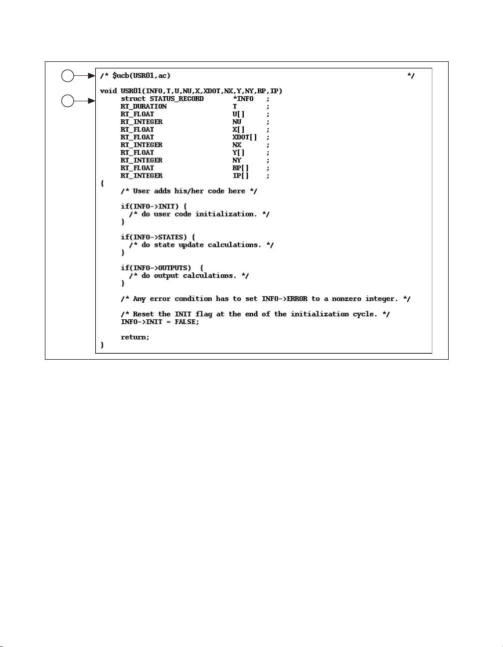
To write code for UserCode Blocks (UCBs), refer to the sa_user.c file,
which is provided in your
The
sa_user.c file contains an example of a UCB function declaration
(refer to the Implementing Handwritten UCBs section). If your model has
more than one UCB, each prototype must have a unique name. Make one
or more copies of this file and insert the code that implements the
algorithm(s) of the UCB(s). One or more uniquely-named UCB code
functions can be placed inside each copy of the
copies can be given any convenient names. If renamed files are included,
the names can be placed into the stand-alone file compilation script
(
compile_c_sa.sh) for automatic compilation. If the UCB function—for
example, USR01, refer to callout 2 of Figure 2-1—is renamed, all other
occurrences of USR01 in
changed appropriately, including the occurrence in directive
to callout 1 of Figure 2-1.
src distribution directory.
sa_user.c file and the
sa_user.c and sa_user.h also must be
$ucb. Refer
© National Instruments Corporation 2-11 AutoCode Reference
Page 29
Chapter 2 C Language Reference
1
2
Figure 2-1. Example UserCode Function File (sa_user.c)
The $ucb directive is recognized and interpreted by the automatic linking
facility of the simulator in SystemBuild to distinguish between UCBs
written for simulation purposes using SystemBuild only and UCBs written
for linking with AutoCode applications. The exact name of the UCB
function must be specified in the
$ucb directive if this UCB function is
used for simulation using SystemBuild.
The computations performed by UCBs can update both block states and
outputs. Execution of each section is controlled by flags set by the
simulator in the INFO structure. Refer to the Implementing Handwritten
UCBs section.
AutoCode Reference 2-12 ni.com
Page 30

Chapter 2 C Language Reference
Implementing Handwritten UCBs
Arguments are passed for each call to the UCB in the following order:
INFO, T, U, NU, X, XDOT, NX, Y, NY, R_P, and I_P
Pointers to all of the arrays (U, X, XD, Y, R_P, I_P) and scalers corresponding
to array sizes (
R_P and I_P arrays must be entered into the UCB dialog to ensure that
proper storage is allocated by the caller. Also, the initial conditions for
states have to be specified in the dialog. Table 2-5 lists the type and purpose
of UCB arguments used in the fixed calling method.
Table 2-5. UCB Calling Arguments and Data Types for the Fixed Interface
Argument Data Type Description
NU, NX, NY) are passed to each call to the UCB. The sizes of
INFO struct STATUS_RECORD*
T RT_DURATION
U[ ] RT_FLOAT
NU RT_INTEGER
X[ ] RT_FLOAT
XDOT[ ] RT_FLOAT
NX RT_INTEGER
Y[ ] RT_FLOAT
NY RT_INTEGER
R_P[ ] RT_FLOAT
I_P[ ] RT_INTEGER
A pointer to STATUS_RECORD structure
representing operation requests and status.
Elapsed time.
An array (of size NU) of inputs to the UCB.
The number of inputs to the UCB.
An array (of size NX) of state variables of
the UCB.
An array (also of size NX). Includes the next
discrete states of
and the derivative of
X for the discrete subsystems,
X for the continuous
subsystems.
The number of states (and next states).
An array (of size NY) of outputs from the UCB.
The number of outputs from the UCB.
An array of real parameters.
An array of integer parameters.
© National Instruments Corporation 2-13 AutoCode Reference
Page 31

Chapter 2 C Language Reference
The operations within UCBs are controlled by the argument INFO, a pointer
to a structure of type
argument list for each UCB (located in
typedef struct STATUS_RECORD
{
} RT_STATUS_RECORD;
The following example shows the general form of UCB equations for
AutoCode and indicates how the
control the computations.
if (INFO->INIT) {
/* do user code initialization */
INFO->INIT = 0;
}
if (INFO->OUTPUTS) {
/* do output calculations having the general form:
Y = H(T,X,XD,U,RP,IP); */
}
if (INFO->STATES) {
/* do state update calculation with the general form:
XD = F(T,X,XD,U,RP,IP); */
}
STATUS_RECORD that is passed as part of the
sa_types):
RT_INTEGER ERROR;
RT_BOOLEAN INIT;
RT_BOOLEAN STATES;
RT_BOOLEAN OUTPUT;
INFO status record pointer is used to
When an error occurs within the UCB, set INFO->ERROR equal to some
nonzero integer value as an error return. Also, make sure that
INFO->INIT
is set to FALSE (0) at the end of the initialization cycle.
The process of linking handwritten UCBs (in
AutoCode application (in
dsp.c) is depicted in Figure 2-2. The
usr_dsp.c) with an
SystemBuild model in Figure 2-2 depicts the filter described by the
difference equation:
y(k) = –1/2 * y(k – 2) + 3 * u(k) + u(k – 2)
The UserCode Block provides the interface to the handwritten function
usr_dsp( ) implemented in the file usr_dsp.c. The usr_dsp( )
function essentially implements the behavior of the same filter.
AutoCode Reference 2-14 ni.com
Page 32

Chapter 2 C Language Reference
File Name: usr_dsp.c
y (k) = -1/2*y(k-2) + 3* u(k) + u(k-2);
which leads to the State-Space realization:
x1(k+1) = x2(k)
x2(k+1) = -1/2* x1(k) - 1/ 2*u(k)
y(k) = x1(k) + 3*u (k)
dsp.c
usr_dsp.c
Generate AutoCode Application
(Handwritten UCB using
sa_user.c
example)
compile
and link
Figure 2-2. Linking Handwritten UCBs with AutoCode Applications
© National Instruments Corporation 2-15 AutoCode Reference
Page 33

Chapter 2 C Language Reference
Linking Handwritten UCBs (for AutoCode) with SystemBuild
After you have written a UCB to create an AutoCode application, you can
use the same UCB for simulation. SystemBuild can automatically compile
and link your UserCode function into the simulation engine (release 4.0 and
later). Refer to Figure 2-3.
SystemBuild provides the
the
sa_user.c example file for writing UCBs. These files are different
usr01.c example file and AutoCode provides
and should not be used interchangeably for linking UCBs with
SystemBuild and AutoCode applications.
user-written code with the SystemBuild simulator.
usr01.c is strictly meant to link
sa_user.c is meant to
link user-written code with AutoCode applications. After the code has been
written using
The
$ucb directive in usr_dsp.c in Figure 2-3 makes it possible to link
sa_user.c, the same file might be linked with SystemBuild.
handwritten UCBs for AutoCode with SystemBuild. However, code
written using
usr01.c, provided by SystemBuild, cannot be linked with an
AutoCode application.
AutoCode Reference 2-16 ni.com
Page 34

simulation (automatic compiling and linking of usr_dsp.c into new UCB shared library)
usr_dsp.c (Handwritten UCB using sa_user.c example)
Chapter 2 C Language Reference
Fleming: usr_dsp.c
Function Name: usr_dsp
simexe.lnx
Figure 2-3. Linking Handwritten UCBs with the SystemBuild Simulator
The arguments to a UCB written only for linking with the SystemBuild
simulator (using
usr01.c) are inherently different than the arguments
to a UCB written for linking with an AutoCode application (using
sa_user.c). This difference stems from several sources. For example,
UCBs written for linking with an AutoCode application might not take
advantage of some features supported in the SystemBuild simulator, such
as linearization. Linearization is not supported in AutoCode generated
code. Also, highly optimized implementation of a UCB tends to be more
of an issue when linking it with AutoCode generated code. If you have
handwritten code for simulation with SystemBuild using the UCB format
in
usr01.c and plan to use the same algorithm with AutoCode-generated
© National Instruments Corporation 2-17 AutoCode Reference
Page 35

Chapter 2 C Language Reference
applications, make sure you adapt the same algorithm in the body of a
function using the AutoCode UCB arguments as in
Variable Interface UCB
The preceding sections described the fixed interface; however, a UCB can
also use the variable interface option. For information on how to specify the
variable interface option, refer to the SystemBuild User Guide. When a
model containing a variable interface UCB is generated, the code to call the
UCB varies depending upon the data types and optional arguments
specified by the UCB. For example, if the UCB does not have any states,
arguments related to states are not passed. The following sections describe
what AutoCode generates for the variable interface.
Interface Ordering
The variable interface consists of arguments required to meet the
specification of the UCB. These arguments are passed relative to a fixed
total ordering of all possible arguments. The following is the total ordering.
Refer to Table 2-5 for descriptions of the arguments:
INFO, T, {u1, u2, ...}, {y1, y2, ...}, {X[], XD[], NX},
{R_P, NRP}, {I_P, NIP}
sa_user.c.
Note
Arguments shown within braces {} are related; either all or none of these arguments
will be generated.
Interface Examples
The following samples of generated code are based on the specification of
a UCB.
/* INFO not used; T used; 2 inputs; 1 output; */
usr01(TIME, in1, in2, &out1);
/* INFO not used; T not used; 1 input; 5IPs */
usr02(in1, &IP[0], 5);
/* INFO used; T not used; 1 output; 4 states */
usr03(&info, &out1, &X[0], &XD[0], 4);
Inputs and Outputs
The fixed interface requires that all inputs and outputs be the floating-point
(RT_FLOAT) data type. However, the variable interface supports all data
types for the inputs and outputs of the UCB. Consequently, this aspect of
the variable interface can lead to errors.
AutoCode Reference 2-18 ni.com
Page 36

Chapter 2 C Language Reference
As previously stated, the inputs and outputs of the UCB will have the same
data type as specified in the model diagram. Inputs are passed by value
while outputs are passed by reference. In addition, the “shape” of an
argument describes whether it is a scalar value or an array. For information
on how to specify the data type and shape of the inputs and outputs of the
UCB, refer to the SystemBuild User Guide.
Another complexity relates to vectorization with AutoCode code
generation. By design, the variable interface UCB is insulated from
the many possible combinations. The interface to the UCB will remain
constant relative to all of the AutoCode optimization. As a result,
AutoCode performs any needed copying—for example, staging—of inputs
and outputs to make sure the proper arguments are passed to the UCB.
For example, if the UCB expects an array of five inputs, yet scalar code is
generated, AutoCode creates a temporary array for those inputs and passes
that temporary array to the UCB.
Function Prototype
National Instruments recommends that you create a function prototype for
your variable interface UCB functions. This will provide some additional
checking that the compiler can do to ensure that the generated interface
matches what you expected without your implementation of the UCB
function.
The following is a sample prototype for a variable interface UCB function:
void ucb01(
RT_FLOAT change[2], /*** inputs ***/
RT_INTEGER xpos,
RT_INTEGER ypos,
RT_FLOAT *rate, /*** outputs ***/
RT_INTEGER posdata[3],
RT_FLOAT *RP, /*** RP ***/
RT_INTEGER NRP
);
© National Instruments Corporation 2-19 AutoCode Reference
Page 37

Chapter 2 C Language Reference
Linking a Variable Interface UCB with the Simulator
Unlike the fixed interface which provides an automatic method for linking
with the Simulator, the variable interface is too complicated for that
method. As a result, you are required to create a “wrapper” function that
interfaces between the Simulator and your code. For information on how to
create the wrapper for the Simulator, refer to the SystemBuild User Guide.
Procedure SuperBlocks
This section describes how to generate and link Procedure SuperBlocks.
Generating Reusable Procedures
Generate a reusable procedure from your Procedure SuperBlock as
described in Chapter 3, Ada Language Reference. Refer to callout 1
of Figure 2-4. Along with the algorithmic procedure (refer to callout 2),
AutoCode also generates the respective hook procedure or wrapper
(refer to callout 3) for automatic linking with the SystemBuild simulator.
Refer to Chapter 5, Generated Code Architecture, and Chapter 9, Global
Scope Signals and Parameterless Procedures, for more information about
generating procedures.
Linking Procedures with the SystemBuild Simulator
Replace the procedure SuperBlock with a UserCode Block (UCB), refer
to callout 4 of Figure 2-4 and place the appropriate file name and function
name in the UCB dialog box entries. The function name should be that of
the Procedure SuperBlock with
When simulating the model, the SystemBuild simulator automatically
compiles and links the generated code, and executes the simulation with the
new code library created at this point.
If more than one Procedure SuperBlock resides in the top-level discrete
SuperBlock from which the procedures are generated, AutoCode will only
generate a UCB wrapper for the first Procedure SuperBlock it encounters.
If you want to generate wrappers for the other Procedure SuperBlocks,
place each Procedure SuperBlock in a separate Discrete SuperBlock and
generate code. You can also modify the template file to generate wrappers
for all procedures in your model by invoking the TPL function
proc_ucb_hook on all Procedure SuperBlocks. Notice how default
template file
SuperBlock, modify it to loop on all Procedure SuperBlocks, and invoke
AutoCode Reference 2-20 ni.com
c_sim.tpl invokes proc_ucb_hook for one Procedure
_ucbhook appended to it.
Page 38

Chapter 2 C Language Reference
proc_ucb_hook. Refer to the Template Programming Language User
Guide.
simulation (automatic compiling and linking
of myproc.c int. new UCB shared library)
2
myproc.c
myproc
SUPER
BLOCK
Procedure
Procedure
1
Generate Reusable Procedure
myproc
USER
CODE
myproc
4
Filename:
Function Name:
myproc_ucbhook
(name of procedure
SuperBlock with
_ucbhook appended to it)
myproc.c
simexe.lnx
3
Figure 2-4. Linking Generated Reusable Procedures
© National Instruments Corporation 2-21 AutoCode Reference
Page 39

Chapter 2 C Language Reference
Linking Procedures with Real-Time Applications or Simulator
Generate reusable procedures from your Procedure SuperBlocks as
described in this chapter and in Chapter 3, Ada Language Reference. To
link generated reusable procedures with your own application or simulator
you have the three following options:
• Invoke the generated algorithmic procedure directly (refer to callout 2
of Figure 2-4), passing it pointers to structure objects as arguments.
• Invoke the re-entrant UCB wrapper routine generated to link with
SystemBuild UCBs (refer to callout 3 of Figure 2-4), passing it
arguments, which are pointers to arrays and values.
• Invoke the generated non-reentrant subsystem function, which invokes
the procedure.
The first option is more efficient for performance reasons, but might not be
the easiest to use. The second option provides ease of use in terms of
argument list and re-entrancy, but is the least efficient in some cases. The
third option also provides ease of use in terms of argument list, but although
the procedure itself is re-entrant, the subsystem invoking the procedure is
not re-entrant.
Invoking Generated Procedures Directly
To invoke a generated algorithmic procedure directly from your own
application, you must have thorough understanding of the arguments to the
procedure. When this is achieved, several steps need to be taken to invoke
the procedure.
The model in Example 2-1 contains a Procedure SuperBlock named
with a time delay block and a BlockScript block. The arguments to the
generated procedure corresponding to Procedure SuperBlock
shown in Figure 2-5.
Example 2-1 Model with Procedure SuperBlock
Depending on the nature of the application, complete the following steps to
invoke the procedure:
1. Create an object of type
_
procedure name
_u and copy in the inputs
to the procedure. A pointer to this object will be passed as argument U
to the procedure.
2. Create an object of type
_
procedure name
_y where the outputs of
the procedure will be stored. A pointer to this object will be passed as
argument Y to the procedure.
AutoCode Reference 2-22 ni.com
proc
proc are
Page 40

Chapter 2 C Language Reference
3. Create an object of type _
procedure name
_s where the states of the
procedure will be stored and initialize all members of the object to 0.0.
This should be done during initialization only. A pointer to this object
will be passed as argument S to the procedure.
Generate Reusable Procedure
Figure 2-5. Arguments to Generated Procedure proc
4. Create an object of type _
procedure-name
_info where the
informational data will be stored and assign proper values to elements
iinfo and rinfo. If Xmath variables or Variable block variables were
used in the procedure, the variable pointers need to be initialized to
© National Instruments Corporation 2-23 AutoCode Reference
Page 41

Chapter 2 C Language Reference
5. Invoke the procedure using pointers to the objects created in steps 1
6. Toggle the state flag of the states object of the procedure—that is, if the
Several of the previous steps are exercised by the other two methods for
invoking generated procedures described in the Linking Procedures with
Real-Time Applications or Simulator section. Details are provided in the
Invoking Procedures Using Generated UCB Wrapper Function section and
the Invoking Procedures Using Generated Subsystem Function section.
Use the generated UCB wrapper and subsystem code as a guide. The UCB
wrapper is generated for the purpose of re-entrancy, thus producing extra
copy in and out of parameter and states variables and control and status
arrays, while the subsystem code is not re-entrant—that is, the states and
information data structures are declared as static such that the need to copy
in and out of variables is no longer necessary.
Invoking Procedures Using Generated UCB Wrapper Function
As described in Chapter 1, Introduction, of the AutoCode User Guide,
when generating a reusable procedure from a Procedure SuperBlock,
a hook procedure or (UCB-style) wrapper along with the algorithmic
procedure, is automatically generated. This wrapper is used by the
SystemBuild simulator to automatically link the procedure for simulation.
The arguments to the wrapper follow the same format of the SystemBuild
explicit UserCode Block. A comment providing information about the
wrapper and its arguments is generated above the wrapper function. You
can use the wrapper directly from your application to invoke the procedure,
but remember that this function is re-entrant, thus exercising copy in and
out of variables that add extra overhead to the application.
point to the appropriate global variables. A pointer to this object will
be passed as argument I to the procedure.
through 4.
value is 0 toggle it to 1, if the value is 1 toggle it to 0—before calling
the procedure again.
Complete the following steps to invoke the wrapper function.
1. Create an array of four elements of type
status and control argument
iinfo, and initialize it properly. Refer to
the SystemBuild User Guide for an explanation of
integer, representing the
iinfo. Only the
first four elements of this array will be used by the generated
procedure. This array will be passed as argument
2. Create an array of four elements of type
double, representing the
iinfo.
timing-related information for the called procedure, and initialize it
AutoCode Reference 2-24 ni.com
Page 42

Chapter 2 C Language Reference
properly. Refer to the SystemBuild User Guide for an explanation of
rinfo. Only the first four elements of this array will be used by the
generated procedure. This array will be passed as argument
rinfo.
3. Create an array sized by the number of inputs in the procedure (refer to
the comment) of type
This array will be passed as argument
int and initialize to the number of inputs in the procedure. A pointer
to this variable will be passed as argument
double and copy in the inputs to the procedure.
U. Also create a variable of type
NU.
4. Create an array sized by the number of outputs in the procedure (refer
to the comment) of type
will be stored. This array will be passed as argument
a variable of type
procedure. A pointer to this variable will be passed as argument
double where the outputs of the procedure
Y. Also create
int and initialize to the number of outputs in the
NY.
5. Create two arrays sized by the number of states in the procedure (refer
to the comment) of type
These arrays will be passed as arguments
(derivatives). Also create a variable of type
double and initialize all elements to 0.0.
X (states) and XD
int and initialize to the
number of states in the procedure. A pointer to this variable will be
passed as argument
NX.
6. Create two arrays sized by the number of integer and real parameters
in the procedure. Refer to the comment of types
int and double and
initialize all elements to 0 and 0.0, respectively. These arrays will be
passed as arguments
I_P and R_P.
7. Invoke the procedure using the arrays and pointers to the variables
created in steps 1 through 6.
Invoking Procedures Using Generated Subsystem Function
When generating a reusable procedure from a Procedure SuperBlock, along
with the algorithmic procedure and the (UCB-style) wrapper, a subsystem
function (
function directly from your application to invoke the procedure, but keep
in mind that this function is not re-entrant, as several variables in this
function are declared static to avoid the overhead of copy in and out of the
variables.
All of the following arguments need to be passed for each call to the
procedure in the following order:
structures reflecting the procedure’s inputs and outputs. The inputs to the
subsystem are provided by the argument
_Subsys_
© National Instruments Corporation 2-25 AutoCode Reference
subsys_
number
number
_in (or _Sys_ExtIn). This structure has mixed
) also is generated. You can use the subsystem
U, Y. These arguments are pointers to
U, a pointer to a structure named
Page 43

Chapter 2 C Language Reference
data-typed variables reflecting each subsystem input signal and type.
The outputs to the subsystem are provided by the argument
to a structure named
data-typed variables reflecting each subsystem output signal and type.
The following overall steps need to be taken to invoke the subsystem
function:
1. Create an object of type
code) and copy in the inputs to the subsystem. A pointer to this object
will be passed as argument
2. Create an object of type
subsystem will be stored. A pointer to this object will be passed as
argument
Y to the subsystem.
3. Invoke the procedure using pointers to the objects created in steps 1
and 2.
C Fixed-Point Arithmetic
Fixed-point calculations provide significant advantages over floating-point
arithmetic. These include:
• Faster execution on most processors
• 8-bit, 16-bit, and 32-bit representations of fixed-point numbers
• Ability to interface to inexpensive processors that do not support
floating-point arithmetic
_Subsys_
_Subsys_1_in (see generated subsystem
_Subsys_1_out where the outputs of the
number
U to the subsystem.
_out. This structure has mixed
Y, a pointer
This section describes the implementation of fixed-point arithmetic in
AutoCode/C.
Note The SystemBuild User Guide has a fixed-point arithmetic chapter that explains the
basics of fixed-point arithmetic and the use of fixed-point arithmetic in SystemBuild
models.
Fixed-Point AutoCode/C Implementation
SystemBuild lets you represent vectors as fixed-point signals to which
fixed-point arithmetic will be applied. Refer to the SystemBuild User
Guide. Fixed-point signals and numbers are represented in AutoCode/C
as integer data types. An associated radix position—that is, the integer
marking the point that divides the integer and fractional part of the
AutoCode Reference 2-26 ni.com
Page 44

Chapter 2 C Language Reference
number—for each integer item and the sign are managed by the code
generator. Arithmetic expressions are scaled to emulate a fixed-point
capability, and all expressions involving the item are coded to be consistent
with the chosen radix position.
AutoCode supports a fixed-point library that implements all of the
fixed-point operations (algebraic, relational, conversion). There are
two different interfaces to the fixed-point library.
• The default and most commonly used one is the macro interface where
the fixed-point operations are encoded as macros.
• The other interface is the function interface where all the fixed-point
operations are implemented as functions. In this interface every
fixed-point operation can result in a function call.
Note If you are using the function interface, compile the AutoCode-generated source file
using the compiler flag
FX_FUNC_INTERFACE.
For example, if your platform is Solaris and you are using the fixed-point
function interface, the command line might appear as:
% acc -o gen_ap -DSOLARIS -DFX_FUNC_INTERFACE
sa_*.o -lm
gen_ap.c
where
gen_ap.c
represents any AutoCode generated source file.
Because fixed-point operations get inlined while using the macro interface,
an application linked with the macro interface will execute at a faster rate
than the same application linked with the function interface.
All the files needed for the macro interface library are present in the
directory
the function interface are present in the directory
function_interface
(
src) is a link to the macro_interface directory. By linking and working
in the directory
to work with the function interface, the user must make the
$CASE/ACC/macro_interface while the files needed for
$CASE/ACC/
. By default, the system-specific source directory
src, the user gets to work with the macro interface. In order
src directory a
link to the function interface. Files common to both directories are present
in both directories.
The supplied macros and functions are written in C. C neither allows
efficient coding of multiplication/division of 32-bit variables, nor does it
take advantage of processor-specific capabilities, such as trapping of
overflows, which can be detected in assembly code by checking the
processor’s status flag. However, you can write functions in assembly
© National Instruments Corporation 2-27 AutoCode Reference
Page 45

Chapter 2 C Language Reference
language and replace the supplied macros (or functions) with your
(assembly) functions so that you can take full advantage of the processor’s
arithmetic capabilities.
Generated Code with Fixed-Point Variables
Code generated for models using fixed-point variables—such as the
examples provided in this chapter—will differ from code generated for
models using floating-point, integer, or logical signals in the following
areas:
• Signal and variable type declarations will reflect fixed-point types.
• Arithmetic operators
arithmetic macro calls (or function calls based on the interface used).
• Relational operators
replaced by fixed-point relational macro calls.
• Floating-point literals used in SystemBuild models will be replaced by
the scaled integer counterpart.
• Macros (or procedures) for converting between various fixed-point
types will be invoked when necessary.
+, –, *, and / will be replaced by fixed-point
>, >=, <, <=, ==, and != will, when necessary, be
Fixed-Point Data Types
Fixed-point type definitions are provided in the system-specific files src
directory. Files
sa_fxlimit.h use typedef statements to represent fixed-point types
and related constants for 8-bit, 16-bit, and 32-bit data. All fixed-point types
have an associated radix position value and a sign (signed or unsigned).
The radix position value is clearly related to the data type scale factor
scale factor = 2
value and the radix position scalar are required. The table below lists the
data types generated by AutoCode/C. For information on ranges and
accuracy of each type, refer to the SystemBuild User Guide.
Data
Type
byte 8 unsigned RT_UBYTE (radix 00)
AutoCode Reference 2-28 ni.com
sa_types.h, sa_defn.h, sa_fxscale.h, and
–(radix position)
Number
of Bits
. To perform any arithmetic operation, both the
Table 2-6. AutoCode/C Data Types
Signed or
Unsigned
Data Type Name
RT_UBYTExx (xx = radix 48 to –16)
signed RT_SBYTE (radix 00)
RT_SBYTExx (xx = radix 48 to –16)
Page 46

Chapter 2 C Language Reference
Table 2-6. AutoCode/C Data Types (Continued)
Data
Type
Number
of Bits
Signed or
Unsigned
Data Type Name
short 16 unsigned RT_USHORT (radix 00)
RT_USHORTxx (xx = radix 48
to –16)
signed RT_SSHORT (radix 00)
RT_SSHORTxx (xx = radix 48
to –16)
long 32 unsigned RT_ULONG (radix 00)
RT_ULONGxx (xx = radix 48 to –16)
signed RT_SLONG (radix 00)
RT_SLONGxx (xx = radix 48 to –16)
A typical fixed-point type looks like the following:
RT_USHORT06
where USHORT stands for unsigned short, and 06 indicates the radix
position.
Fixed-point variables that are always positive in nature can be declared as
unsigned. This has the advantage of providing one more bit of accuracy
than with signed fixed-point variables, because the most significant bit is
used for storing the sign in that data type.
Example 2-2 shows some of the I/O type declarations. Only the significant
parts of the code are shown.
Example 2-2 Fixed-Point C I/O Type Declarations
struct _Subsys_1_out {
RT_SSHORT13 SS13;
RT_SSHORT15 SS15;
RT_SSHORT15 SS15_1;
RT_USHORT14 US14;
RT_USHORT10 US10;
RT_SSHORT13 SS13_1;
RT_SSHORT12 SS12;
RT_SSHORT08 SS8;
© National Instruments Corporation 2-29 AutoCode Reference
Page 47

Chapter 2 C Language Reference
RT_SSHORT05 SS5;
RT_SSHORT SS0;
RT_SSHORT05 SS5_1;
};
struct _Sys_ExtIn {
RT_USHORT13 US13;
RT_SSHORT14 SS14;
};
/******* System Ext I/O type definitions. *******/
struct _Subsys_1_out subsys_1_out;
struct _Sys_ExtIn sys_extin;
static RT_FLOAT ExtIn [NUMIN+1];
static RT_FLOAT ExtOut [NUMOUT+1];
/******** Procedures’ declarations ********/
/******* Procedure: proc *******/
/***** Inputs type declaration. *****/
struct _proc_u {
RT_USHORT13 US13;
};
/***** Outputs type declaration. *****/
struct _proc_y {
RT_SSHORT13 SS13;
RT_SSHORT15 SS15;
RT_SSHORT15 SS15_1;
RT_USHORT14 US14;
RT_USHORT10 US10;
RT_SSHORT13 SS13_1;
RT_SSHORT12 SS12;
};
/***** Info type declaration. *****/
struct _proc_info {
RT_INTEGER iinfo[5];
};
User Types
You can define your own data types (called user types or UTs) in terms of
the intrinsic types using the Xmath UT editor. UTs and the UT editor are
described in the SystemBuild User Guide.
AutoCode Reference 2-30 ni.com
Page 48

Overflow Protection
Chapter 2 C Language Reference
The UTs appear as typedef statements in the generated C code. For
example:
typedef volts RT_SBYTE03;
This code defines the data type called volts to be a signed byte with radix
position 3.
Overflow is defined as loss of significance—that is, a computation losing
bits in the integer part of the number. The term underflow is used to mean
overflow on a negative number.
An Overflow Protection capability is provided to protect against overflows.
Overflow Protection consists in detecting an overflow condition and
replacing the overflowed number with the extremal value for the data type
of the number—the maximum positive number if the overflowed number
was positive; the maximum negative number if it was negative.
Overflow can be efficiently detected in assembly code by examining the
processor status flags, whereas in C, these flags are not available, making
it necessary to test the results for consistency.
Most macros and functions with overflow protection have been combined
into sets of signed and unsigned macros and functions, and combinations
of both. This was done because overflow protection is different for signed
and unsigned operands. This difference is due to the difference in lower and
upper limits of signed and unsigned types. An unsigned type has 0 as the
lower limit, whereas a signed type has a negative number as the lower limit.
However, given the same word length and value position, the upper limit of
a signed type is always smaller than the upper limit of an unsigned type.
Overflow protection is performed in all macros and functions that have a “p”
at the end of the macro name. Examples of these macros are listed in the
Conversion Macros section and the Arithmetic Macros section.
Overflow protection is controlled by the
0
causes generation of unprotected macros, and specifying -ovfp 1 causes
generation of protected macros. The default is to generate protected
macros.
-ovfp option. Specifying -ovfp
Stand-Alone Files
All of the stand-alone files, with the exception of sa_types.h, have a
common prefix
© National Instruments Corporation 2-31 AutoCode Reference
sa_fx, indicating fixed-point functionality.
Page 49

Chapter 2 C Language Reference
Macro Interface
The macro interface files are:
sa_types.h Updated to include fixed-point types.
sa_fx.h Contains fixed-point conversion macros.
sa_fxp.h Contains fixed-point conversion macros with
sa_fxr.h Contains fixed-point relational macros.
sa_fxm.h Contains fixed-point arithmetic macros.
sa_fxmp.h Contains fixed-point arithmetic macros with
sa_fx_temps.h Contains the declaration information for
sa_fxprv.h Contains macros used only by the other macros.
sa_fxscale.h Contains scale factor constants for different radix
sa_fxlimit.h Contains maximum and minimum values that can
sa_fxadd_byte.c Contains fixed-point addition functions for byte
sa_fxadd_short.c Contains fixed-point addition functions for short
sa_fxadd_long.c Contains fixed-point addition functions for long
sa_fxsub_byte.c Contains fixed-point subtraction functions for byte
sa_fxsub_short.c Contains fixed-point subtraction functions for
sa_fxsub_long.c Contains fixed-point subtraction functions for
sa_fxmul_long.c Contains fixed-point multiplication functions for
sa_fxdiv_long.c Contains fixed-point division functions for long
overflow protection.
overflow protection. For 32-bit division and
multiplication, overflow sometimes cannot be
detected.
temporary variables used in fixed-point
computations.
values.
be represented in different fixed-point types.
data type.
data type.
data type.
data type.
short data type.
long data type.
long data type. Multiplication for byte and short
data types are completely implemented as macros.
data type.
AutoCode Reference 2-32 ni.com
Page 50

Function Interface
Chapter 2 C Language Reference
sa_fx_externs.c Contains definitions for extern variables such as
mask buffers that are read only.
The function interface files are:
sa_types.h Updated to include fixed-point types.
sa_fxp.h Contains fixed-point conversion macros with
overflow protection.
sa_fxr.h Contains fixed-point relational macros.
sa_fxm.h Contains fixed-point arithmetic macros.
sa_fxmp.h Contains fixed-point arithmetic macros with
overflow protection. For 32-bit division and
multiplication, overflow sometimes cannot be
detected.
sa_fx_temps.h Contains the declaration information for
temporary variables used in fixed-point
computations.
sa_fxprv.h Contains macros used only by the other macros.
sa_fxscale.h Contains scale factor constants for different radix
values.
sa_fxlimit.h Contains maximum and minimum values that can
be represented in different fixed-point types.
sa_fx_f.h Contains prototypes for fixed-point conversion
functions without overflow protection.
sa_fxp_f.h Contains prototypes for fixed-point conversion
functions with overflow protection.
sa_fxm_f.h Contains prototypes for fixed-point algebraic
functions without overflow protection.
sa_fxmp_f.h Contains prototypes for fixed-point algebraic
functions with overflow protection
sa_fxadd_byte.c Contains fixed-point addition functions for byte
data type.
sa_fxadd_short.c Contains fixed-point addition functions for short
data type.
sa_fxadd_long.c Contains fixed-point addition functions for long
data type.
© National Instruments Corporation 2-33 AutoCode Reference
Page 51

Chapter 2 C Language Reference
sa_fxsub_byte.c Contains fixed-point subtraction functions for byte
sa_fxsub_short.c Contains fixed-point subtraction functions for
sa_fxsub_long.c Contains fixed-point subtraction functions for
sa_fxmul_byte.c Contains fixed-point multiplication functions for
sa_fxmul_short.c Contains fixed-point multiplication functions for
sa_fxmul_long.c Contains fixed-point multiplication functions for
sa_fxdiv_byte.c Contains fixed-point division functions for byte
sa_fxdiv_short.c Contains fixed-point division functions for short
sa_fx_f.c Contains fixed-point conversion functions with
sa_fxp_f.c Contains fixed-point conversion functions without
sa_fxm_f.c Contains fixed-point algebraic functions without
sa_fxdiv_long.c Contains fixed-point division functions for long
sa_fx_externs.c Contains definitions for extern variables such as
data type.
short data type.
long data type.
byte data type.
short data type.
long data type.
data type.
data type.
overflow protection.
overflow protection.
overflow protection.
data type.
mask buffers that are read only.
These stand-alone files have naming conventions based on the functionality
of the macros and whether or not the macros support overflow protection.
Refer to the Overflow Protection section. For example, the
sa_fxm.h file
contains macros performing arithmetic functions that do not have overflow
protection, but file
that perform similar functions. There only is one file (
sa_fxmp.h contains macros with overflow protection
sa_fxr.h) for
relational macros as overflow protection is not a concern for macros
implementing relational operations.
AutoCode Reference 2-34 ni.com
Page 52

Fixed-Point Conversion and Arithmetic Macros
Although this section explains different fixed-point operations in terms of
macros, all of these operations are supported as functions in the function
interface. Hence, in the following sections the term macro can be
completely substituted by the term function.
Three types of fixed-point macros are generated by AutoCode:
• Conversion macros that convert one type of number to another. Refer
to the Conversion Macros section.
• Arithmetic macros that perform addition, subtraction, multiplication,
or division. Refer to the Arithmetic Macros section.
• Relational macros that compare two numbers and produce a Boolean
result. Refer to the Fixed-Point Relational Macros section.
Conversion Macros
Conversion macros are used for converting from one fixed-point data type
to another, from floating-point to fixed-point or from fixed-point to
floating-point, or from integer to fixed-point or from fixed-point to integer.
These macros in turn make use of the left-shift or right-shift macros defined
sa_fxprv.h.
in
Chapter 2 C Language Reference
The right-shift macro shifts the bits of a value to the right. When a negative
number is shifted right, it results in flooring of that number instead of
truncating because of the two’s complement scheme of representing
negative numbers. Therefore, the right-shift macro with truncate behavior
checks for a negative number and does the needed adjustment to produce
truncation.
Whenever a fixed-point number needs to be aligned, a right-shift macro can
be called. Addition, subtraction, multiplication, division, and the relational
macros all make use of the alignment macros. Therefore, the right-shift
macro can be heavily used. If you can accept floor behavior for negative
numbers, you could replace the truncate macro with the floor macro, which
can increase the execution speed of the generated code. To do so, modify
the implementation of the (shift-right) macros
SHRslpt in the sa_fxprv.h file to perform a simple right-shift operation
SHRsbpt, SHRsspt, and
as follows:
#define SHRsbpt(x,y) ((x) >> (y))
#define SHRsspt(x,y) ((x) >> (y))
#define SHRslpt(x,y) ((x) >> (y))
© National Instruments Corporation 2-35 AutoCode Reference
Page 53

Chapter 2 C Language Reference
Figures 2-6 through 2-8 show how the conversion macros are named.
Notice that macro names have no embedded spaces.
sr wr ALIGN so wo p q(n, rp)
Figure 2-6. AutoCode/C Conversion Macros for Fixed-to-Fixed Conversions
For example, the macro to convert an unsigned 8-bit number to a signed
8-bit number with a shift of
sbALIGNubp(n,rp)
n = Fixed-point operand to align
rp = Number of bits to shift
(if rp < 0, perform a left-shift;
if rp > 0, perform a right-shift)
q = optional answer quantization (r, c, or f)
r = round the answer
c = ceiling the answer
f = floor the answer
default (no r, c, or f) is truncate the answer
p = Overflow protection (optional)
wo = Operand wordsize (b=byte, s=short, l=long)
NOTE: The operand wordsize must be equal
to or larger than the result wordsize
so = Operand sign (u=unsigned, s=signed)
ALIGN (indicates conversion)
wr = Result wordsize (b=byte,
(see NOTE above)
sr = Result sign (u=unsigned, s=signed)
s=short, l=long)
rp bits, and with overflow protection is:
AutoCode Reference 2-36 ni.com
Page 54

i ALIGN so wo p (n, rp)
Figure 2-7. AutoCode/C Conversion Macros for Fixed-to-Integer Conversions
For example, the macro to convert an unsigned 8-bit number to an integer
number with a shift of
iALIGNubp(n,rp)
Chapter 2 C Language Reference
n = Fixed-point operand to align
rp = Number of bits to shift
(if rp < 0, perform a left-shift;
if rp > 0, perform a right-shift)
p = Overflow protection (optional)
wo = Operand wordsize (b=byte, s=short, l=long)
so = Operand sign (u=unsigned, s=signed)
ALIGN (indicates conversion)
i = Indicates integer result
rp bits, and with overflow protection is:
sr wr ALIGN i p (n, rp)
n = Fixed-point operand to align
rp = Number of bits to shift
(if rp < 0, perform a left-shift;
if rp > 0, perform a right-shift)
p = Overflow protection (optional)
i = Indicates integer input
ALIGN (indicates conversion)
wr = Result wordsize (b=byte, s=short, l=long)
sr = Result sign (u=unsigned, s=signed)
Figure 2-8. AutoCode/C Conversion Macros for Integer-to-Fixed Conversions
For example, the macro to convert an integer number to a signed 8-bit
number with a shift of
sbALIGNip(n,rp)
© National Instruments Corporation 2-37 AutoCode Reference
rp bits, and with overflow protection is:
Page 55

Chapter 2 C Language Reference
Arithmetic Macros
The arithmetic macros perform addition, subtraction, multiplication, and
division. The top level macros for arithmetic operations are present in the
sa_fxm.h and sa_fxmp.h files. These macros in turn call the ALIGN
macros that are defined either in
whether or not they are overflow protected. The macros for addition and
subtraction also make use of addition and subtraction functions defined in
sa_fxmp.c.
Figure 2-9 shows how the arithmetic macros are named. Notice that macro
names have no embedded spaces.
sr wr op _ s1 w1 _ s2 w2 p (n1,n2,rp1, rp2, rp3)
sa_fx.h or sa_fxp.h, depending on
n1 = First fixed-point operand
n2 = Second fixed-point operand
rp1 = Radix position for n1
rp2 = Radix position for n2
rp3 = Radix position for result
p = Overflow protection (optional)
s2= sign of n2 (u=unsigned, s=signed)
w2= size of n2 (b=byte, s=short, l=long)
_ (underscore character; part of macro name)
s1 = sign of n1 (u=unsigned s=signed)
w1 = size of n1 (b=byte, s=short, l=long)
_ (underscore character; part of macro name)
op = ADD, SUB, MUL, or DIV
wr = Result wordsize (b=byte, s=short, l=long)
sr = Result sign (u=unsigned, s=signed)
Figure 2-9. AutoCode/C Arithmetic Macros
AutoCode Reference 2-38 ni.com
Page 56

Chapter 2 C Language Reference
Table 2-7 shows permissible operand and result sizes for the arithmetic
macros.
Table 2-7. Arithmetic Macros—Operand and Result Sizes
Operation Operand 1 Size Operand 2 Size Result Size
addition
subtraction
multiplication
division
(operand 1 is the
dividend; operand 2
is the divisor)
byte byte byte or short
short short short or long
long long long
byte byte byte
short byte byte
short short short
long short short
long long long
For example, the macro to add two 8-bit unsigned numbers with overflow
protection and produce an unsigned 8-bit result is:
ubADD_ub_ubp(n1,n2,rp1,rp2,rp3)
The macro to subtract a 16-bit unsigned number from a 16-bit signed
number with overflow protection and produce an unsigned 16-bit result is:
usSUB_ss_usp(n1,n2,rp1,rp2,rp3)
The macro to multiply two 16-bit signed numbers with overflow protection
and produce a 16-bit signed result is:
ssMUL_ss_ssp(n1,n2,rp1,rp2,rp3)
The macro to divide two 32-bit signed numbers with overflow protection
and produce a 32-bit signed result is:
slDIV_sl_slp(n1,n2,rp1,rp2,rp3)
© National Instruments Corporation 2-39 AutoCode Reference
Page 57

Chapter 2 C Language Reference
Implementation of the Addition and Subtraction Macros
AutoCode has two implementations of the addition and subtraction macros:
• Macros that apply wordsize extension (also called extended
• Macros that do not apply wordsize extension.
For example, when using wordsize extension in an 8-bit processor, addition
of two 8-bit operands results in a 16-bit addition operation, because the
8-bit addition macro internally extends the wordsize of the operands from
8 bits to 16 bits.
Not using the wordsize extension on 8-bit and 16-bit processors provides
faster operations. However, you can lose precision if the result radix
position is not smaller than the radix positions of the two operands.
Alignment of the radix positions of the operands to the result radix position
can overflow the 8-bit variable capacity, causing a saturation and loss of
accuracy. Example 2-3 shows this.
intermediate types) to the two operands before aligning the radix
positions and adding or subtracting. This is the default
implementation. Wordsize extension provides greater accuracy, but is
slower because the operations are performed in a larger wordsize than
specified.
Example 2-3 Using Wordsize Extension
Subtraction of fixed-point number n1 = (17, r4) and fixed-point
number
n2=(32,r5), to produce a fixed-point result number n3 with
radix position 7, using 8-bit signed variables for both the operands and the
result.
Method 1: Using Wordsize Extension
In binary representation:
0001^0001 (n1 = (17,r4), decimal value = 1.0625)
—
001^00000
Extend the wordsize of
in
n1' and n2':
00000000 0001^0001 (n1' = (17,r4), decimal value = 1.0625)
—
00000000 001^00000
AutoCode Reference 2-40 ni.com
(n2 = (32,r5), decimal value = 1.0)
n1 and n2 to 16 bits, and place the extended results
(n2' = (32,r5), decimal value = 1.0)
Page 58

Chapter 2 C Language Reference
Align the radix positions of n1 and n2 to the radix position of the result
before subtracting (that is, shift
two bits). Place the aligned results in
subtraction of
00000000 1^0001000 (n1' = (136,r7), decimal value = 1.0625)
—
00000000 1^0000000
n1' and n2', and store the result in n3':
n1 left by three bits, and shift n2 left by
n1' and n2' and perform a 16-bit
(n2' = (128,r7), decimal value = 1.0)
_______________________
00000000 0^0001000 (n3' = (8,r7), decimal value = .0625)
Change the result back to an 8-bit signed number in
0^0001000 (n2 = (8,r7), decimal value = .0625)
n3:
Method 2: Not Using Wordsize Extension
In binary representation:
0001^0001 (n1 = (17,r4), decimal value = 1.0625)
—
001^00000
Align the radix positions of
before subtracting (that is, shift
two bits). Place the aligned results in
subtraction of
sign bit
|
0001^0001
Detect overflow before aligning to radix position 7, correct overflow (that
is, use maximum number possible)
0^1111111 (n1' = (127,r7), decimal value = .9921875)
(n2 = (32,r5), decimal value = 1.0)
n1 and n2 to the radix position of the result
n1 left by three bits, and shift n2 left by
n1' and n2' and perform an 8-bit
n1' and n2', and store the result in n3:
(n1 = (17,r4), decimal value = 1.0625)
001^00000 (n2 = (32,r5), decimal value = 1.0)
Detect overflow before aligning to radix position 7, correct overflow (that
is, use maximum number possible)
0^1111111 (n2' = (127,r7), decimal value = .9921875)
0^1111111 (n1' = (127,r7), decimal value = .9921875)
—
© National Instruments Corporation 2-41 AutoCode Reference
Page 59

Chapter 2 C Language Reference
0^1111111 (n2' = (127,r7), decimal value = .9921875)
___________
0^0000000 (n3 = (0,r7), decimal value = 0.0)
In Example 2-3, method 1 is more accurate than method 2, but it is also less
efficient because it involves a 16-bit subtraction. This is important for
those using 8-bit processors but will probably not be as significant for
those using 16-bit or 32-bit processors.
Method 2 was inaccurate because of the left-shifting that had to be
performed for alignment to the result radix. If the result radix position had
been the same as the radix position of one of the operands, the resultant
value would have been as accurate as with method 1 even though it used
only 8-bit subtraction.
Selecting Wordsize Extension in the Preprocessor Macro
You can choose whether or not to use wordsize extension in addition
and subtraction by a preprocessor macro in the
preprocessor statement:
#define WORDSIZE_EXTEND 1
sa_fxp.h file. The
causes the code to be compiled with wordsize extension. This is the
default. The preprocessor statement:
#define WORDSIZE_EXTEND 0
causes the code to be compiled without wordsize extension.
32-Bit Multiplication and Division Macros
32-bit multiplication and division macros are different from their 8-bit and
16-bit counterparts. This is because the maximum wordsize available is
only 32 bits; therefore, operands cannot be promoted to a higher word
length before or after performing multiplication or division.
32-Bit Multiplication
Before performing the actual multiplication, both operands are split into
upper and lower words. Multiplication is performed in parts—that is,
higher and lower words of each operand are multiplied by each other and
added in a certain fashion to produce a 64-bit intermediate result. This
intermediate result is aligned according to the result’s radix position. After
alignment, if the value cannot be held in 32 bits, the clipped value—that is,
AutoCode Reference 2-42 ni.com
Page 60

Chapter 2 C Language Reference
the maximum possible value representable in 32 bits—is returned. This
multiplication process can be expensive because it involves several
multiplication and addition operations to produce an intermediate result.
This procedure strives for accuracy, but a user can speed up the process by
giving up some of the accuracy.
32-Bit Division
As with 32-bit multiplication, operands are split into higher and lower
words. This method is based on Euclidean division or repeated division.
The higher and lower words of the numerator are divided by the higher and
lower words of the denominator. The remainder obtained from this step is
repeatedly divided to get components of the quotient. These components
are added up to get the final quotient. As with 32-bit multiplication, this can
be costly because of several addition, division, and multiplication
operations needed to calculate the intermediate results. Again, you can
speed up the routine at the cost of accuracy.
16-Bit by 8-Bit Division
Depending on the radix value of the operands and the result, this operation
might result in either an iterative division or a fast-shift-based division.
For example, let
with radix value
r1 – (r2) – (r3) ≤ BYTE_SIZE
where BYTE_SIZE is 8, it will result in a call to an iterative division.
Otherwise, it will be a fast-shift-based division. The iterative division
method is costly in terms of speed, but is needed to compute an accurate
result. By changing this behavior, you can speed up the operation if you are
willing to give up some accuracy.
n1 be the dividend with radix value r1, n2 be the divisor
n2, and n3 be the result with radix value r3. If the term:
32-Bit by 16-Bit Division
Depending on the radix value of the operands and the result, this operation
might result in either an iterative division or a fast-shift-based division.
For example, let
with radix value
term:
r1 – (r2) – (r3) ≤ WORD_SIZE
where WORD_SIZE is 16, results in a call to an iterative division. Otherwise,
it will be a fast-shift-based division. The iterative division method is costly
© National Instruments Corporation 2-43 AutoCode Reference
n1 be the dividend with radix value r1, n2 be the divisor
n2, and n3 be the result with radix value r3. The following
Page 61

Chapter 2 C Language Reference
in terms of speed, but is needed to compute an accurate result. By changing
this behavior, you can speed up the operation if you are willing to give up
some accuracy.
Note For more information on the implementation of multiplication and division macros,
refer to the SystemBuild User Guide.
Fixed-Point Relational Macros
The relational macros compare two numbers and return a Boolean result
(true or false). Macros for relational operations are defined in
These macros are defined in terms of low-level relational macros present in
sa_fxprv.h.
Figure 2-10 shows how the relational macros are named. Notice that macro
names have no embedded spaces.
bool op _ s1 w1 _ s2 w2 (n1,n2,rp1, rp2)
sa_fxr.h.
n1 = First fixed-point operand
n2 = Second fixed-point operand
rp1 = Radix position for n1
rp2 = Radix position for n2
s2 = sign of n2 (u=unsigned, s=signed)
w2 = size of n2 (must = size of n1; see w below)
_ (underscore character; part of macro name)
s1 = sign of n1 (u=unsigned, s=signed)
w1 = size of n1 (b=byte, s=short, l=long)
_ (underscore character; part of macro name)
op = GT, GE, LT, LE, EQ, NEQ
GT = greater than
GE = greater than or equal
LT = less than
LE = less than or equal
EQ = equal
NEQ = not equal
bool = indicates Boolean relational operation
Figure 2-10. AutoCode/C Relational Macros
AutoCode Reference 2-44 ni.com
Page 62

For example, the macro to check an 8-bit unsigned number and an 8-bit
signed number for equality and produce a Boolean result is:
boolEQ_ub_sb(n1,n2,rp1,rp2)
Some Relevant Issues
• The fixed-point macros used by AutoCode-generated files are defined
• The fixed-point algebraic operations that involve more than
• Because the C preprocessor has a limit on the length of macros,
Chapter 2 C Language Reference
in the
sa files and are available to you for making modifications. If the
AutoCode macros are changed, the results might not match the Sim
results. To change Sim so that the results again match, generate
procedures-only fixed-point code (which uses the AutoCode
fixed-point macros) and, through a UserCode Block (UCB),
automatically link the generated code with the simulation engine.
Refer to the UserCode Block section of Chapter 5, Generated Code
Architecture.
two operands pose the problem of order dependency of the
operation—that is, the operation can become nonassociative).
For example, the expression y = a + b + c can result in different values
if evaluated as (a + b) + c instead of a + (b + c). Sorting the expression
in a separate loop—for example, in the generated code for the model
summing junction—is not performed by AutoCode due to the
computational overhead. Refer to the SystemBuild User Guide for
more details.
it can process, the amount of nesting in the macros must be limited.
Therefore, if a summing junction has more than six additions or
subtractions, then in the generated code the additions or subtractions
are broken down into multiple statements, and the intermediate result
is stored in the destination signal (operand). For fixed-point
computations, certain rules are used for coming up with the
intermediate data type. If the summing junction is broken down into
multiple statements in the generated code, the intermediate rules are
influenced by the type of the destination signal (operand) present in
each statement. This might result in some loss of accuracy.
© National Instruments Corporation 2-45 AutoCode Reference
Page 63

Ada Language Reference
This chapter discusses files used to interface AutoCode and the generated
Ada code to your specific platform and target processor. This chapter also
discusses target-specific utilities needed for simulation and testing.
Stand-Alone Simulation
The templates provided for Ada code generation produce code that, when
compiled, form a stand-alone simulation. This simulation can be executed
with MATRIXx data as input, and produces results that can be loaded back
into Xmath for analysis. You must compile the generated code along with
the stand-alone library to produce the simulation executable.
Chapter 2, Using AutoCode, of the AutoCode User Guide describes a
process to compile the code and stand-alone library, generate sample input
data, and load the data into Xmath for analysis.
Supported Ada Compilers for the Stand-Alone Library
Ada’83 is extremely portable. The generated code from either of the
standard templates is in complete conformance with Ada’83 and no
vendor-specific extensions are used. However, there can be variations in
the run-time environments supplied by Ada vendors that require different
implementations, especially related to floating-point and fixed-point
numerics. Three versions of Ada run-time environments that require
slightly different implementations of the stand-alone library. If your Ada
vendor is not specifically listed in Table 3-1, try one of the versions
identified for your platform type. If the code compiles, it will most likely
work. The names of the run-time environments correspond to the names of
directories within the AutoCode distribution.
3
© National Instruments Corporation 3-1 AutoCode Reference
Page 64

Chapter 3 Ada Language Reference
Table 3-1. Identified Ada Run-Time Versions of the Stand-Alone Library
Solaris, UNIX Ver d i x
HP-UX/DOS Alsys
Windows 2000/NT/9x/DOS ActivAda
Supplied Templates
ada_rt.tpl Template
The ada_rt.tpl template is the default when generating Ada code. This
template uses Ada tasks to implement the scheduling mechanism for the
model. This template supports fixed-point arithmetic.
ada_sim.tpl Template
The ada_sim.tpl template does not use Ada tasks to implement a
scheduler. The subsystems and procedures of a model execute as fast as
possible. This template is similar in design to the
generation. The execution results of a model generated using this template
should allow for easier comparison to SystemBuild Simulator results. Also,
the time to execute a model is significantly faster than one based on the
ada_rt.tpl.
Platform Stand-Alone Library
c_sim.tpl for C code
ada_fxpt_sys.tpl Template
The ada_fxpt_sys.tpl template is included in the ada_sim.tpl and
ada_rt.tpl templates. This template contains segments that generate the
operator instantiation package. The segments have been modularized to
reduce the impact of fixed-point support in the
templates. This template uses the system-level tokens to generate the
operator instantiations.
ada_sim and ada_rt
ada_fxpt_sub.tpl Template
The ada_fxpt_sub.tpl template file can be included instead of the
ada_fxpt_sys.tpl in the ada_sim.tpl and ada_rt.tpl. This
template uses the subsystem/procedure-level tokens to generate the
instantiations. Each subsystem and procedure has a different package and
source file generated.
AutoCode Reference 3-2 ni.com
Page 65

Chapter 3 Ada Language Reference
Stand-Alone Library
This section describes the system-specific and target-specific stand-alone
(
sa_*) files supplied with your system.
System-Specific Files
Header and source files are supplied to interface AutoCode generated code
to your development platform, and to the target processor in your test bed
or rapid-prototyping system.
Both specifications and the source files are provided in your source
directory:
• Specification files have the suffix
systems.
• Body files have the suffix
.a or .ada on most UNIX systems.
The names of the distribution directories and files are shown in Table 3-2.
Table 3-2. Distribution Directories and Files
Category UNIX Windows
_.a or _.ada on most UNIX
Top-Level Directory $MTXHOME
(Environment variable)
Executables Directory: $MTXHOME/bin
Executable: autostar
Utilities Directory: $CASE/ACA/src
Files: sa_*.a or sa_*.ada
Script: compile_ada_sa.sh
Notes: A soft link to Alsys or
Verdix directory.
Directory:
$CASE/ACA/alsys
Files: sa_*.ada
Notes: SA files for Alsys Ada
compiler.
Directory:
$CASE/ACA/verdix
Files: sa_*.a
Notes: SA files for VERDIX Ada
compiler.
© National Instruments Corporation 3-3 AutoCode Reference
%MTXHOME%
(Environment variable)
Directory: %MTXHOME%\bin
Executable: autostar
Directory: %CASE%\ACA\src
Files: sa_*.a
Script:
compile_ada_sa.bat
Notes: A copy of the Verdix directory
files.
Directory:
%CASE%\ACA\alsys
Files: sa_*.ada
Notes: SA files for Alsys Ada
compiler.
Directory:
%CASE%\ACA\verdix
Files: sa_*.a
Notes: SA files for VERDIX Ada
compiler.
Page 66

Chapter 3 Ada Language Reference
Table 3-2. Distribution Directories and Files (Continued)
Category UNIX Windows
Templates Directory:
$CASE/ACA/templates
Templates: ada_rt.tpl,
ada_intgr.tpl, ada_sim.tpl
Compiled Template: ada_rt.dac,
ada_sim.dac
Directory: %CASE%\ACA\templates
Templates: ada_rt.tpl,
ada_intgr.tpl, ada_sim.tpl
Compiled Template: ada_rt.dac,
ada_sim.dac
Demos Directory: $XMATH/demos Directory: %XMATH%\demos
• The principal file is sa_utils.a (or sa_utils.ada), the
stand-alone utilities file. When you compile
sa_utils.a/.ada,
you must make the following files from the source distribution
directory available locally:
– sa_utils_.a/.adasa_utils.a/.ada
– sa_time_.a/.adasa_time.a/.ada
– sa_math_.a/.adasa_math.a/.ada
– sa_fmath_.a/.adasa_fmath.a/.ada
– sa_types_.a/.adasa_io.a/.ada
– sa_defn_.a/.ada
• If you are compiling to run with the Real-Time/Expert Block, the
following files must be available locally:
–
sa_exprt_.a/.adasa_exprt.a/.ada
– sa_aiq_.a/.adasa_aiq.a/.ada
• If you are compiling to run with the Real-Time/Fuzzy Logic Block, the
following files must be available locally:
– sa_fuzzy_.a/.adasa_fuzzy.a/.ada
• If you have defined any hand-written UserCode Blocks, these header
files must be available locally:
– sa_user_.a/.adasa_user.a/.ada
• When you compile your generated code program, all of the previous
files must be available.
For use with generated Ada code, mathematical functions are supplied in
the
sa_fmath.a/.ada file, using type RT_FLOAT. A set of auxiliary math
functions that are needed to support AutoCode/Ada generated programs
can be found in the AutoCode/Ada supplied package
sa_math.a/.ada.
These functions are required even if they are supported by your native Ada
AutoCode Reference 3-4 ni.com
Page 67

Chapter 3 Ada Language Reference
floating-point MATH_LIB. The sa_time.a/.ada file provides the
Elapsed_Time_Of( ) function.
The purposes of the more important specification files are listed in
Tabl e 3-3.
.
Table 3-3. Target-Specific Utility Routines
File Purpose
sa_types_.a
sa_defn_.a
sa_utils_.a
Defines the supported data types.
Defines constants and error codes for generated code.
Defines external function prototypes for the
stand-alone utilities.
sa_math_.a
Defines special math functions used by generated
code.
sa_fmath_.a
Used only by Verdix compilers to re-export functions
already supported by the Ada math library.
sa_time_.a
sa_user.a
Declares time-related variables and functions.
Defines function prototypes for UCBs.
Data Types
Several of the target-specific utilities are involved with data types; three
data types (declared in
Generator:
RT_FLOAT Corresponds to Ada type FLOAT.
RT_INTEGER Corresponds to Ada type INTEGER.
RT_BOOLEAN Corresponds to Ada type BOOLEAN.
sa_types.a/ada) are defined for the Ada Code
At compilation, you must make available the specification file
sa_types_.a (or sa_types_.ada), which declares these types, along
with corresponding array types. This file is in the source distribution
directory on your system and you can edit a copy of the file as required.
Certain global record, array, and exception types are also defined in
this file. The record type
sa_types_.a/.ada and is used when UserCode Blocks are referenced.
© National Instruments Corporation 3-5 AutoCode Reference
RT_STATUS_RECORD is declared in
Page 68

Chapter 3 Ada Language Reference
Target-Specific Utilities
The target-specific utilities in the sa_utils.a or sa_utils.ada file
perform hardware-, application-, and Ada-specific tasks that are required
for simulation and testing. They can be modified to support the generated
code on the target computer. As furnished, these routines simulate I/O
operations that would occur in a simulation environment, using import files
created using MATRIXx. These files are to be used unmodified for
comparing your simulations with generated code outputs. However, for
target-system usage on your rapid prototyping or end-user system, these
routines can be modified or rewritten completely and recompiled for the
target system. When you do this, be sure to keep a copy of the unmodified
file and keep separate versions of the files in separate directories. There is
no requirement that the file be named
you use must be specified for compilation and linking. Inside the file, the
names of all the external variables, functions, and other references must be
preserved.
As furnished for this release, the routines are written in Ada, but this is not
required. If you rewrite the routines, they should still be written in a
language that offers direct control of the I/O and interrupt hardware of the
target computer and that can be linked to the object form of the generated
Ada program. Normally, these utilities need to be created only once for
each target computer. In general, a given set of target-specific utilities need
only be changed when the target hardware is modified. The routines are
shown in Table 3-4.
sa_utils.a; however, the name
Table 3-4. Target-Specific Utility Routines
Routine Function
Enable( )
Disable( )
Background( )
Error,fatalerr( )
Implementation_Initialize( )
Unmask timer interrupt.
Mask timer interrupt.
Background polling loop.
Error handlers.
Initialize I/O hardware and perform other
implementation-specific initialization tasks.
Implementation_Terminate( )
External_Input( )
AutoCode Reference 3-6 ni.com
Perform implementation-specific termination tasks.
Collect external inputs.
Page 69

Chapter 3 Ada Language Reference
Table 3-4. Target-Specific Utility Routines (Continued)
Routine Function
External_Output( )
Signal_Remote_Dispatch( )
The sa_utils.a or sa_utils.ada file contains comments about each of
the routines as they are used for comparing simulation with generated code
results.
Enable( ), Disable( ), and Background( ) Procedures
Enable, disable, and background routines are not needed when the
application scheduler is written in terms of the Ada tasking model. They are
furnished as null stubs in the
have a system that requires intervention in this area, place the required code
in these procedures.
Error Procedure( ) Procedure
procedure Error(NTSK: in RT_INTEGER;
ERR_NUM: in RT_INTEGER)
Error( )
execution; not all reported conditions are errors. These functions can be
invoked for deactivating all necessary functions and then passing an alarm
to the external environment or for initiating recovery action. You can
choose either to return from an error function or to halt the machine.
Post external outputs.
Multiprocessor implementations only; signal secondary
processors that a dispatch table is available.
sa_utils.a or sa_utils.ada file. If you
reports conditions detected by the generated code during
The
RT_INTEGER variable ERR_NUM is passed if an error occurs in running
the generated code. The following conditions are trapped. Not all of them
necessarily indicate that an error has occurred. The following messages
may be generated during the execution of the generated code:
Stop Block encountered in task
n
This is not necessarily an error. This refers to a SystemBuild Stop
Simulation Block, encountered in the execution of the generated code.
Math Error encountered in task
n
Check your model for possible overflows, divisions by zero, and so on.
User code error encountered in task
© National Instruments Corporation 3-7 AutoCode Reference
n
Page 70

Chapter 3 Ada Language Reference
Refer to the Chapter 14, UserCode Blocks, of the SystemBuild User Guide
or the source listing of the USR01 routine for meanings of UCB errors. You
are allowed to extend the scope of these messages, so it might be one of
yours.
Unknown error encountered in task
A possible cause is an incorrect user-written error condition in the
generated code.
Time overflow occurred in task
This indicates a subsystem (or task) overflow. Also, you might get this
error if the generated real-time code is run on non-real-time systems.
Unexpected error in task
This message occurs if an error other than any of the previous examples
is encountered.
Implementation_Initialize( ) Procedure
procedure Implementation_Initialize
(NUMIN:in RT_INTEGER;
NUMOUT:in RT_INTEGER,
SCHEDULER_FREQ:in RT_FLOAT)
n
n
n
In the default (simulation comparison) version of the sa_utils.a/.ada
file, this function initializes the inputs and outputs for the system by loading
input data from the user-furnished
Xmath {matrixx, ascii} formatted
input file. In the version of this routine that you write to make the generated
code work with the target computer, this routine performs many kinds of
implementation-specific initialization processes for the real-time system.
These processes include:
• Initializing the clock-timer of the target system to request interrupts at
the minor cycle of the control system; that is, the time period required
between interrupts for synchronous operation of the various tasks, as
calculated by AutoCode from the block diagrams
• Initializing the interrupt system of the target computer
• Initializing the math coprocessor, if any
• Setting up shared memory and other hardware-dependent processes
• Initializing I/O hardware
AutoCode Reference 3-8 ni.com
Page 71

Chapter 3 Ada Language Reference
By default, several error conditions are trapped in the procedure
Implementation_Initialize of sa_utils.a/.ada, but you can
expand this capability in your own versions of the program, detecting your
own error conditions and adding your own messages.
The Ada exception processing facility is used and you are encouraged to
define and raise exceptions in your versions of the
Implementation_Initialize procedure.
The generated messages displayed in the default version of the
sa_utils.a/.ada file are listed below. These messages pertain to the
processing of the input and output files for execution of generated code:
*** File opened is not in Xmath {matrixx, ascii} format.
Load the file into Xmath, save in {matrixx, ascii} format, then try
again.
*** Incorrect file version. Must be at least V7.0.
The input data file was generated using an obsolete version of MATRIXx.
Load the file into Xmath, save it from the Xmath Commands window, and
try again. Notice that
V7.0 refers to the version of the file save routine, not
to the version of MATRIXx.
*** Invalid file name
Check to see that the correct Ada file naming conventions are used.
*** Error opening input file
Check to see that the correct Ada file usage conventions are used.
***Input file contains more than two arrays.
***Input time vector has more than one column.
***Input time vector cannot be an imaginary number.
***Input array dimensions must be TIME_POINTS X NUMBER
OF INPUTS
***Input array cannot contain imaginary numbers.
All the previous messages indicate a bad input file.
*** First time point must be zero.
An input time vector must start at zero.
*** Time vector size exceeds storage limit.
*** Input array size exceeds storage limit.
© National Instruments Corporation 3-9 AutoCode Reference
Page 72

Chapter 3 Ada Language Reference
These messages indicate that the sizes of the time vector and input array
have exceeded one or more of the storage allocation size limits established
by
very beginning of the stand-alone utilities file, just after the trademark
notice. Refer to the comments in the file and adjust the limits accordingly;
then recompile and relink the utilities file. If the input time vector size is
adjusted, the output time vector must be adjusted to maintain its size as
twice the input time vector. As a rule of thumb, the maximum input values
should be equal to the maximum output values, plus the maximum time
outputs.
*** Output storage exceeds storage limit.
The size of the input file has exceeded the storage allocation size limits
established by
along with the input size limits discussed previously. Refer to the
comments at the beginning of the file and adjust the limits accordingly,
and then recompile and relink.
Implementation_Terminate( ) Procedure
procedure Implementation_Terminate
sa_utils.a/.ada. These limits are established as constants at the
sa_utils.a/.ada. This limit is established as a constant
In the default simulation comparison version of the sa_utils.a/.ada
file, this procedure completes the I/O processing for the execution of the
system by writing output data to the output file and closing the file.
You can write a version of this routine to make the generated code work
with the target computer. In addition to data completion tasks, this routine
can be called upon to perform many kinds of implementation-specific
shutdown processes for the real-time system. These include:
• Freeing up shared memory and other resources
• Completing the posting of all outputs
• De-initializing I/O hardware
External_Input ( ) Procedure
procedure External_Input(Bus: out RT_REAL_ARRAY;
UE_PTR: in RT_INTEGER;
NUMIN: in RT_INTEGER;
SCHEDULER_STATUS: out INTEGER)
External_Input( )
It samples input data values from an input pool previously loaded into
memory. In the target version of
is for use in simulation comparison mode.
sa_utils.a/.ada, the operation of
AutoCode Reference 3-10 ni.com
Page 73

Chapter 3 Ada Language Reference
External_Input( ) is much the same; it returns an input vector from
the software data bus.
SCHEDULER_STATUS, which is passed to it by the scheduler.
External_Input( ) returns the value of
External_Output( ) Procedure
procedure External_Output(Bus: in RT_REAL_ARRAY;
YE_PTR: in RT_INTEGER;
NUMOUT: in RT_INTEGER;
SCHEDULER_STATUS: out INTEGER)
External_Output
is for use in simulation comparison mode. It
places output data values into an output pool in memory. In the target
version of
sa_utils.a/.ada, the operation of External_Output( )
is much the same; it posts an output vector to the software data bus.
External_Output( ) returns the value of SCHEDULER_STATUS,
which is passed to it by the scheduler.
UserCode Blocks
This section describes how to link UserCode Blocks (UCBs) with
AutoCode or SystemBuild applications.
Linking Handwritten UCBs with AutoCode Applications
To write the implementation code for UserCode Blocks (UCBs), refer to
the
sa_user_.a/.ada and sa_user.a/.ada files, which are provided
in your
the calling sequence described in the Calling UCBs section. Make one or
more copies of these files and insert your code that implements the
functionality of the UCBs. You can place one or more uniquely named
UCB code procedures inside each copy of the
sa_user.a/.ada files and give the copies any convenient names. If you
include renamed files, place the names in the stand-alone file compilation
script (
src directory. These files contain an example of the declaration of
sa_user_.a/.ada and
compile_ada_sa.sh) for automatic compilation.
The computations performed by UCBs can update both block states and
outputs.
© National Instruments Corporation 3-11 AutoCode Reference
Page 74

Chapter 3 Ada Language Reference
Calling UCBs
Every one of the following arguments will be passed for each call to the
UCB in the following order:
INFO, T, U, NU, X, XD, NX, Y, NY, R_P, I_P
Within the UCB, the elements of all the array variables (U, X, XD, Y, R_P,
I_P) must be accessed as in the following example:
U(U'first), U(U'first+1), ... U(U'first+NU-1)
X(X'first), X(X'first+1), ... X(X'first+NX-1)
Make sure to access the elements in the above manner as all the arrays are
passed as array slices. The sizes of
UCB block form to ensure that proper storage is allocated in the caller.
Also, the initial conditions for states have to be specified in the form.
Table 3-5 lists the type and purpose of UCB arguments used in the fixed
calling method.
Table 3-5. UCB Calling Arguments and Data Types
Argument Data Type Description
R_P and I_P must be entered in the
INFO:in out RT_STATUS_RECORD
T:in RT_DURATION
U:in RT_REAL_ARRAY
NU:in RT_INTEGER
X:in out RT_REAL_ARRAY
XD:in out RT_REAL_ARRAY
NX:in RT_INTEGER
Y:in out RT_REAL_ARRAY
NY:in RT_REAL_ARRAY
R_P:in out RT_REAL_ARRAY
NRP:in out RT_INTEGER
A structure representing operation requests and
status.
Elapsed time.
An array (of size NU) of inputs to the UCB.
The number of inputs to the UCB.
An array (of size NX) of state variables of the UCB.
An array (of size NX). Defines the next discrete
states of X for discrete subsystems, and the derivative
of X for the continuous subsystems.
The number of states (and next states).
An array (of size NX). Defines the next discrete
states of X for discrete subsystems, and the derivative
of X for the continuous subsystems.
The number of outputs from the UCB.
An array of real parameters.
The number of real parameters.
AutoCode Reference 3-12 ni.com
Page 75

Chapter 3 Ada Language Reference
Table 3-5. UCB Calling Arguments and Data Types (Continued)
Argument Data Type Description
I_P:in out RT_INTEGER
NIP:in out RT_INTEGER
The operations within UCBs are controlled by the INFO argument, a record
of
RT_STATUS_RECORD type that is passed as part of the argument list for
each UCB:
type RT_STATUS_RECORD is
record
ERROR: RT_INTEGER;
INIT: RT_BOOLEAN;
STATES: RT_BOOLEAN;
OUTPUTS: RT_BOOLEAN;
end record;
The following example shows the general form of UCB equations and
indicates how the
if INFO.INIT then
-- do user code initialization
INFO.INIT := FALSE;
end if;
if INFO.OUTPUTS then
-- do output calculations having the general form:
-- Y := h(T,X,XD,U,R_P,I_P);
end if;
if INFO.STATES then
-- do state update calculations with the general form:
-- XD := f(T,X,XD,U,R_P,I_P);
end if;
An array of integer parameters.
The number of integer parameters.
INFO status record is used to control the computations.
When an error occurs within the UCB, set INFO.ERROR:= some nonzero
integer value as an error return. Also, make sure that
INFO.INIT is set to
FALSE at the end of the initialization cycle.
To link UCBs (either handwritten or generated) with generated scheduled
subsystem code, compile the UCBs, required
sa_* files, and the generated
scheduled subsystem code and link them together to build an application.
© National Instruments Corporation 3-13 AutoCode Reference
Page 76

Chapter 3 Ada Language Reference
Procedure SuperBlocks
This section describes how to generate and link Procedure SuperBlocks.
Generating Reusable Procedures
Generate reusable procedures from your Procedure SuperBlocks as
described in Chapter 2, Using AutoCode, of the AutoCode User Guide.
You have an option to call the generated algorithmic procedures directly
(refer to Example 3-1), passing it pointers to record objects as arguments,
or you can call the hook routine with a fixed UCB calling style interface,
passing it arguments, which are arrays and values. The former option is
more efficient for performance reasons, but the latter provides for
backward compatibility in terms of argument list.
Refer to Chapter 5, Generated Code Architecture, for more information.
Linking Procedures with Real-Time Applications or Simulator
Linking Ada procedures (either handwritten or generated) back
with SystemBuild for simulation requires the use of pragmas or
implementation-dependent features for calling Ada subprograms
from languages other than Ada (refer to Example 3-1).
Example 3-1 Linking Generated Reusable Procedures
-------- Procedure: myproc -------...
package myproc_pkg is
...
procedure myproc(U : myproc_u_t_P;
Y : myproc_y_t_P;
I : myproc_info_t_P);
end myproc_pkg;
...
package body myproc_pkg is
procedure myproc(U : myproc_u_t_P;
Y : myproc_y_t_P;
I : myproc_info_t_P) is
...
begin
-- Body of the procedure - end myproc;
end myproc_pkg;
AutoCode Reference 3-14 ni.com
Page 77

Chapter 3 Ada Language Reference
-----------------------------------------------------------------------
-- Wrapper around the procedure to support UCB (Fixed calltype) interface
-- This routine can be called as a UCB either from SystemBuild or AutoCode
-----------------------------------------------------------------------
-----------------------------------------------------------------------
-- Map
-- ---
-- Number of Inputs: 2
-- Number of Outputs: 3
-- Number of States: 0
-- Number of Integer parameters: 0
-- Number of Real parameters: 0
-- ...
----------------------------------------------------------------------...
with myproc_pkg; use myproc_pkg;
procedure myproc_hook(
iinfo : in out RT_STATUS_RECORD;
TIME : in RT_DURATION;
U : in RT_FLOAT_AY;
NU : in RT_INTEGER;
X : in RT_FLOAT_AY;
XD : in out RT_FLOAT_AY;
NX : in RT_INTEGER;
Y : in out RT_FLOAT_AY;
NY : in RT_INTEGER;
R_P : in out RT_FLOAT_AY;
I_P : in out RT_INTEGER_AY) is
...
begin
...
myproc(ptr_of(myproc_12_u'address), ptr_of(myproc_12_y'address),
ptr_of(myproc_12_i'address));
...
end myproc_hook;
© National Instruments Corporation 3-15 AutoCode Reference
Page 78

Chapter 3 Ada Language Reference
Ada Fixed-Point Arithmetic
This section describes the implementation of fixed-point arithmetic in
AutoCode/Ada. It is assumed that you are familiar with the Ada
programming language.
Note The SystemBuild User Guide has a fixed-point arithmetic chapter that explains the
basics of fixed-point arithmetic and the use of fixed-point arithmetic in SystemBuild
models.
How to Generate Real-Time Code
Using AutoCode, you can generate Ada high-level language code. Refer to
the Template Programming Language User Guide or to Chapter 2, Using
AutoCode, of the AutoCode User Guide for additional information. To
generate code to run on your local host, you can generate code from one of
the following:
• SystemBuild, which lets you automatically generate a real-time file
(
.rtf) and then source code from a model, using a Graphical User
Interface. This is the recommended method of generating code to run
on your local host.
• Xmath, which lets you automatically generate an
source code from a model, using an Xmath command.
• The operating system prompt, which lets you generate source code
from an already-existing
from the operating system prompt.
.rtf file and then
.rtf file, using the autostar command
Fixed-Point AutoCode/Ada Architecture
This section describes the architecture of Fixed-Point AutoCode/Ada.
Consult an Ada language reference manual if you are not familiar with any
of the terms in this section. The basis for this architecture is the use of the
fixed-point type mechanism provided in Ada. This basis enables the use of
generic functions to implement the functionality of standard operations,
such as addition and subtraction. Overloaded operators are created as
instances of the generic functions for only those combinations of
fixed-point data types used in the model. The use of overloaded operators
maximizes code readability.
AutoCode Reference 3-16 ni.com
Page 79

Chapter 3 Ada Language Reference
Fixed-Point Data Types
Fixed-point type declarations exist in the file named: sa_fxptypes_.a
and is provided in the System-Specific Files
This file contains the specification of the
src (source) directory.
SA_FIXED package. The package
specification contains all of the type declarations with the appropriate
delta and range for each type. Refer to the AutoCode Reference for more
information about the fixed-point type sizes, radix ranges and naming
conventions.
Note Ada uses the term delta to describe the accuracy of a fixed-point type.
AutoCode/Ada uses the term radix to denote a type’s accuracy. The relationship between
the two is: delta = 2
–radix
. Thus, a fixed-point type with a delta of 0.125 is a fixed-point type
with radix 3.
1
Generic Functions
Generic functions that implement functionality of standard operations
are found in the two files named:
sa_fxpgenerics.a. These files provide the specification and body for
the
SA_FIXED_GENERICS package. These files are also provided in the
System-Specific Files
src directory. These generic functions are the basis
for the creation of the overloaded operators to perform the appropriate
arithmetic operation.
sa_fxpgenerics_.a and
Instantiated Functions
Due to the large number of combinations of operations and fixed-point
types, only those operations that are used in the model are
instantiated—that is, only the instances of the functions that are required by
a model are actually created. Thus, an additional file is created by the code
generator when generating code for a model that uses fixed-point types.
This file is generated from the template. The default template generates one
additional file that contains a package specification containing all of the
instantiated functions for the model. The package name is
RT_FIXED_OPERATORS and the file is named fxp_
where
outputfile
is the name of the model or other name as specified in
a command option to AutoCode.
1
The file name convention uses an underscore before the extension to denote a file containing a package specification.
The
.a extension is arbitrary as different platforms use different extensions, like .ada.
© National Instruments Corporation 3-17 AutoCode Reference
outputfile
_.a,
Page 80

Chapter 3 Ada Language Reference
Package Dependencies
The fixed-point AutoCode/Ada architecture forces a dependency among
the supplied and generated code for a model that uses any fixed-point types.
This dependency affects compilation order within an Ada Library.
Figure 3-1 illustrates the imposed dependency. In the figure, a package that
is beneath a package and connected to a package above it by an arrow is
said to be dependent on the package that is above.
SA_TYPES
(Standard types package)
SA_FIXED
(Fixed-point types package)
RT_FIXED_OPERATORS
(Generated instantiations)
Generated Ada code for
SA_FIXED_GENERICS
(Generic functions)
SA_FIXED_GENERICS
Body
the Model
Figure 3-1. Package Dependency Graph
AutoCode Reference 3-18 ni.com
Page 81

Generated Code with Fixed-Point Variables
Fixed-point arithmetic operations are accomplished by overloading the
standard arithmetic operators for the fixed-point types. Therefore, the
generated code with fixed-point variables uses the same infix expressions
that non-fixed-point variables normally use, except for the following
modifications:
• The package name must be used when referring to a fixed-point type.
• Explicitly defined conversion functions are used to convert a
fixed-point value to any other numeric type.
• No-Op conversion-like functions are used to disambiguate infix
subexpressions.
• Initialization of fixed-point variables with negative literals use the
pre-defined negate operator to specify a negative value.
• Tests for equality with a fixed-point type are coded using equivalent
logical expressions. The expression a = b will be generated as
(
a >= b and a <= b), and the expression a/=b will be
generated as (
type variable or expression.
a<b||a>b), when a and/or b is a fixed-point
Chapter 3 Ada Language Reference
User Types
A User Type (UT) is a type that is specified using the Xmath User Type
editor and appears in the generated code as a type name. UTs and the
UT editor are described in more detail in the SystemBuild User Guide.
For generated Ada code, all UTs are placed in a package named
USER_TYPES. The package declares a UT as a subtype of the base type of
the UT. For example, the UT named volts is declared in the
USER_TYPES
package as shown in Figure 3-1.
subtype volts is SA_FIXED.RT_SBYTE03;
In other words, the data type volts is a subtype of the signed byte with
radix 3 fixed-point type. Notice that UTs are not restricted to fixed-point
base types. The package name must be used to refer to a user type for
declaring variables.
© National Instruments Corporation 3-19 AutoCode Reference
Page 82

Chapter 3 Ada Language Reference
System-Level Parameters to Generate User Types
Table 3-6 describes new system-level parameters that are used to generate
the
USER_TYPES package.
Table 3-6. System-Level Parameters to Generate User Types
Name Description
Overflow Protection
n_user_defined_type_i
The number of user types in the current
model.
usertype_name_ls
An array of strings that contain the
names of all of the user types in the
model. Array size is
n_user_defined_type_i.
usertype_basename_ls
An array of strings that contain the
names of all the base types of the user
types of the model. Array size is
n_user_defined_type_i.
Overflow is defined as loss of significance—that is, a computation
resulting in a value that cannot be represented in the range of a specific
fixed-point type. Overflow refers to a value larger than the largest number
in the type range, and underflow refers to a value smaller than the smallest
number in the type range.
For the standard Ada fixed-point types, if an overflow occurs, an exception
is raised. AutoCode/Ada provides the capability to detect and correct an
overflow condition in a fixed-point computation. This is accomplished
within the implementations of the generic functions in the
SA_FIXED_GENERICS package.
The implementation provided for each of the generic functions uses
exception handlers to detect when an overflow occurs. Correction is
performed by examining the values of the function and replacing the
overflowed value with the extreme value for the data type; the largest
number if an overflow, the smallest number if an underflow.
The reliance upon exceptions to detect overflow conditions can be
computationally expensive as it may require a significant number of
machine instructions to handle the exception. As a result, execution times
can suffer. However, if a particular data type used in a calculation is
AutoCode Reference 3-20 ni.com
Page 83

Caution The provided implementations of the generic functions implement a behavior that
is numerically correct and matches the SystemBuild Simulator’s results. Any change to the
generic functions can severely affect the numeric results of a model. Do not attempt to
change the implementation unless you are fully aware of the intricacies of fixed-point
numerics.
Stand-Alone Files
File Name Package Name Description
Chapter 3 Ada Language Reference
frequently overflowing, a different data type should be selected. If you are
concerned about performance and the use of an exception handler for
detecting overflow, the generic functions can be changed. These changes do
not affect the generated code in any way. Thus, you can freely modify the
generic function implementations without having to regenerate the model.
Support for the AutoCode/Ada Fixed-Point architecture is found within
files in the System-Specific Files
the fixed-point specific files. Notice that the
src directories. Table 3-7 contains all of
.a extension depends on the
Ada compiler you use.
Table 3-7. Fixed-Point Stand-Alone Files
sa_fxptypes_.a SA_FIXED
Contains all fixed-point type
declarations.
sa_fxpgenerics_.a SA_FIXED_GENERICS
Specification of the generic
function.
sa_fxpgenerics.a SA_FIXED_GENERICS
Package body that implements the
generic functions.
sa_fxpbit_.a SA_FIXED_BITWISE_FUNCTIONS
Package specification containing
bitwise operations on radix 0
fixed-point types.
sa_fxpbit.a SA_FIXED_BITWISE_FUNCTIONS
Package body of the bitwise
operations on fixed-point types.
Compilation Example
This section illustrates the steps required to generate and compile a model
that includes fixed-point types. For the purpose of this example, assume a
top-level superblock name of
© National Instruments Corporation 3-21 AutoCode Reference
gaintest.
Page 84

Chapter 3 Ada Language Reference
1. Build a model—Use the SuperBlock Editor to construct a model that
uses fixed-point types for input/output signals. Refer to the
SystemBuild User Guide for more information.
2. Generate real-time code—From the SystemBuild pull-down menus,
select Build»Generate Real-Time Code. In the AutoCode dialog
box, select Ada Code Generation and continue. Example 3-2 shows
a sample transcript that should appear in the Xmath window during
code generation.
Example 3-2 Example Code Generation Transcript
Analyze complete for SuperBlock gaintest.
New Real Time File saved to /home/test/gaintest.rtf
*********************************************************
* AutoCode/Ada Code Generator 7.X *
* *
* (C) Copyright 2000. National Instruments Corporation.*
* Unpublished work; Restricted rights apply. *
* All rights reserved. Portions U.S. Patent. *
*********************************************************
Loading 'gaintest.rtf' ...
Initializing ...
Building symbols ...
Executing 'ada_rt.dac' :
Generating procedures package declarations ...
Generating subsystems package declarations ...
Generating the scheduler ...
Generating subsystems package bodies ...
Generating procedures package bodies ...
Output generated in gaintest.a
Generating fixed point operators package specification ...
Generating operator instantiations ...
Generating conversion instantiations ...
Output generated in fxp_gaintest_.a
Code generation complete
3. Compile the stand-alone files—Before compiling the generated Ada
code, all of the stand-alone files must be compiled into the Ada
Library. Sample scripts are provided to create an Ada Library in the
current working directory and compile all of the stand-alone files into
it. The stand-alone files need only be compiled once into the Ada
Library.
AutoCode Reference 3-22 ni.com
Page 85

4. Compile the generated files—Two source files are generated,
gaintest.a and fxp_gaintest_.a, as shown in Figure 3-1. The
imposed package dependencies (refer to the Package Dependencies
section) require that the
into the Ada Library before the code that represents the model. Thus,
the file
fxp_gaintest.a is compiled before gaintest.a.
5. Create an executable—This is the final step and it creates an
executable file. Refer to your Ada compiler documentation on how
to complete this step.
Fixed-Point Type Declarations
Within the SA_FIXED package, all of the supported fixed-point data type
are declared. Table 3-8 summarizes the fixed-point type specifications.
Table 3-8. Fixed-Point Data Type Summary
Chapter 3 Ada Language Reference
RT_FIXED_OPERATORS package be compiled
Range
2
Name
1
Range
Delta
2
(smallest .. largest)
Radix
RT_ S BYTExx –16..48 2.0 ** (–r) –(2.0 ** 7 – r)..((2.0 ** 7 – r) – (2.0 ** (–r)))
RT_ U BYTExx –16..48 2.0 ** (–r) 0.0 .. ((2.0 ** 8 – r) – (2.0 ** (–r)))
RT_SSHORTxx –16..48 2.0 ** (–r) –(2.0 ** 15 – r)..((2.0 ** 15 – r) – (2.0 ** (–r)))
RT_USHORTxx –16..48 2.0 ** (–r) 0.0 .. ((2.0 ** 16 – r) – (2.0 ** (–r)))
RT_SLONGxx –16..48 2.0 ** (–r) –(2.0 ** 31 – r)..((2.0 ** 31 – r) – (2.0 ** (–r)))
RT_ U LONGxx
1
xx denotes a two-digit number representing the radix, like 03 or 12.
2
r denotes a specific radix.
3
Ada compiler limitations restrict the range of the data types to be the same as if the data types were signed.
3
–16..48 2.0 ** (–r) 0.0 .. ((2.0 ** 31 – r) – (2.0 ** (–r)))
Generic Functions
The generic functions that are used to instantiate overloaded operators and
other functions are found in the
found in the
sa_fxpgenerics_.a and sa_fxpgenerics.a files.
Table 3-9 summarizes the functions and their purpose. Refer to the package
specification for more details.
SA_FIXED_GENERICS package, which is
© National Instruments Corporation 3-23 AutoCode Reference
Page 86

Chapter 3 Ada Language Reference
Table 3-9. Generic Function Summary
Function Name Purpose
FIXED_ADD
FIXED_SUB
FIXED_MUL
FIXED_DIV
FIXED_IDENTITY
SIGNEDNEGATION
UNSIGNEDNEGATION
SIGNEDABS
UNSIGNEDABS
LESSTHAN
GREATERTHAN
Addition of two fixed-point values.
Subtraction of two fixed-point values.
Multiplication of two fixed-point values.
Division of two fixed-point values.
The identity property of a fixed-point
value.
Negation for a value of a signed
fixed-point type.
Negation for a value of a unsigned
fixed-point type.
Absolute value for a value of a signed
fixed-point type.
Absolute value for a value of a unsigned
fixed-point type.
Tests less-than relation between values
of two different fixed-point types.
Tests greater-than relation between
values of two different fixed-point types.
LESSEQUAL
Tests less-than or equal to relation
between values of two different
fixed-point types.
GREATEREQUAL
Tests greater-than-or-equal-to relation
between values of two different
fixed-point types.
INTCAST
Fixed-point value to RT_INTEGER
conversion.
INTCAST_TRUNC
Fixed-point value to RT_INTEGER
conversion using truncation.
INTCAST_ROUND
Fixed-point value to RT_INTEGER
conversion using rounding.
AutoCode Reference 3-24 ni.com
Page 87

Chapter 3 Ada Language Reference
Table 3-9. Generic Function Summary (Continued)
Function Name Purpose
LONGINTCAST
LONGINTCAST_TRUNC
LONGINTCAST_ROUND
BOOLEANCAST
INTFIXEDCAST
LONGINTFIXEDCAST
BOOLEANFIXEDCAST
FLOATFIXEDCAST
FLOATFIXEDCAST_TRUNC
Fixed-point value to
RT_LONG_INTEGER conversion.
Fixed-point value to
RT_LONG_INTEGER conversion using
truncation.
Fixed-point value to
RT_LONG_INTEGER conversion using
rounding.
Fixed-point value to RT_BOOLEAN
conversion.
RT_INTEGER to a fixed-point type
conversion.
RT_LONG_INTEGER to a fixed-point type
conversion.
RT_BOOLEAN to a fixed-point type
conversion.
RT_FLOAT to a fixed-point type
conversion.
RT_FLOAT to a fixed-point type
conversion with truncation.
FLOATFIXEDCAST_ROUND
RT_FLOAT to a fixed-point type
conversion with rounding.
FIXED_CAST
Conversion between two different
fixed-point types.
FIXED_CAST_TRUNC
Conversion between two different
fixed-point types with truncation.
FIXED_CAST_ROUND
Conversion between two different
fixed-point types with rounding.
NOOPCAST
© National Instruments Corporation 3-25 AutoCode Reference
Conversion to the same fixed-point type.
Page 88

Chapter 3 Ada Language Reference
Bit-Wise Functions
A restricted set of bit-wise operations have been defined for certain
fixed-point types. These functions exist in the
SA_FIXED_BITWISE_FUNCTIONS package found in the sa_fxpbit_.a
and
sa_fxpbit.a files. The set of bit-wise operations are the following
three functions:
value.
BCLEAR clears the nth bit of a value. BSET sets the nth bit of a value.
The functions are overloaded to accept values that are of a fixed-point type
with radix 0. That includes
RT_USHORT, RT_SLONG, and RT_ULONG. Bit-wise operations on
fixed-point data types can only be done using variable blocks.
Note The Ada templates provided by multiprocessor do not generate code that WITHs or
USEs the SA_FIXED_BITWISE_FUNCTIONS package. If you decide to use any of those
functions, you must modify the template to include both the
package. Refer to the Template Programming Language User Guide for information about
the templates.
Instantiated Functions Package
AutoCode/Ada will generate one additional file for a model if it
contains any fixed-point type. This file contains the package for the
RT_FIXED_OPERATORS package. This package contains all of the
instantiations for every overload operator and conversion function that
are used in the model.
BTEST, BCLEAR, and BSET. BTEST tests the nth bit of a
RT_SBYTE, RT_UBYTE, RT_SSHORT,
WITH and USE clauses for this
Note All of the instantiated functions should have an Ada pragma directive to inline the
function. This eliminates the function call overhead associated with overloading operators.
Due to some Ada compiler inconsistencies, these directives are commented out of the
generated package. A small modification to the template can enable these directives. Refer
to the Template Programming Language User Guide for information about the templates.
Operator Instantiations
The RT_FIXED_OPERATORS package contains instantiations for
overloaded operators. These include the Ada operators:
<, <=, >, >=, ABS
SA_FIXED_GENERICS package is chosen to instantiate the overload.
. The appropriate generic function from the
Relational operators can be optimized if the data types of both arguments
are the same. In that case, a new function is not instantiated and the
predefined relational operator is renamed so that it is visible.
AutoCode Reference 3-26 ni.com
+, -, *, /,
Page 89

Chapter 3 Ada Language Reference
Conversion Function Instantiations
The RT_FIXED_OPERATORS package contains instantiations of functions
that represent conversion of values to and from a fixed-point type. The
appropriate generic function from the
chosen to instantiate the function. The name of the instantiated function
follows a convention that indicates what type of conversion is to be done.
Table 3-10 defines the naming convention for conversion functions.
Table 3-10. Conversion Function Naming Conventions
SA_FIXED_GENERICS package is
Conversion Type Name
Fixed to RT_INTEGER RT_YYxx_I
Fixed to RT_INTEGER (truncation) RT _YYxx_It
Fixed to RT_INTEGER (round) RT_ YYxx_Ir
Fixed to RT_LONG_INTEGER RT_ YYxx_LI
Fixed to RT_LONG_INTEGER (truncation) RT_YYxx_LIt
Fixed to RT_LONG_INTEGER (round) RT_YYxx_LIr
Fixed to RT_BOOLEAN RT_YYxx_B
Fixed to RT_FLOAT RT_ F LOAT
RT_INTEGER to Fixed RT_YYxx
RT_LONG_INTEGER to Fixed RT_ YYxx
RT_BOOLEAN to Fixed RT_YYxx
RT_FLOAT to Fixed RT _YYxx
RT_FLOAT to Fixed (truncation) RT_YYxxt
RT_FLOAT to Fixed (round) RT_ YYxxr
Fixed to Fixed (different types) RT_YYxx
1
Fixed to Fixed (different types, truncation) RT_YYxxt
Fixed to Fixed (different types, round) RT_YYxxr
Fixed to Fixed (same type, no-op cast) YYxx
1
YY indicates the short name of a fixed-point type xx is the two-digit radix.
© National Instruments Corporation 3-27 AutoCode Reference
Page 90

Chapter 3 Ada Language Reference
Sample Package
Example 3-3 shows a generated RT_FIXED_OPERATORS package.
Example 3-3 Generated RT_FIXED_OPERATORS Package
---------------------------------------------------------------------------
-- AutoCode/Ada (TM) Code Generator 7.X --
-- National Instruments Corporation, Austin, Texas --
---------------------------------------------------------------------------
-- rtf filename : feed.rtf
-- Filename : fxp_feed_.a
-- Dac filename : ada_sim.dac
-- Generated on : Fri Jun 2 14:44:02 1999
-- Dac file created on : Thu Jun 1 16:19:31 1999
--
-- Fixed Point Operator Instantiation Package
--
--
with SA_TYPES;
with SA_FIXED;
with SA_FIXED_GENERICS;
package RT_FIXED_OPERATORS is
-- Operator Instantiations --
function "+" is new SA_FIXED_GENERICS.FIXED_ADD(
SA_FIXED.RT_SSHORT15,
SA_FIXED.RT_SSHORT15,
SA_FIXED.RT_SSHORT15,
SA_FIXED.RT_SLONG15);
--pragma inline ("+");
function “-” is new SA_FIXED_GENERICS.FIXED_SUB(
SA_FIXED.RT_USHORT13,
SA_FIXED.RT_USHORT15,
SA_FIXED.RT_SSHORT12,
SA_FIXED.RT_ULONG12);
--pragma inline ("-");
function "-" is new SA_FIXED_GENERICS.FIXED_SUB(
SA_FIXED.RT_SSHORT12,
SA_FIXED.RT_SSHORT15,
SA_FIXED.RT_SSHORT14,
SA_FIXED.RT_SLONG14);
--pragma inline ("-");
AutoCode Reference 3-28 ni.com
Page 91

Chapter 3 Ada Language Reference
function “>=” is new SA_FIXED_GENERICS.GREATEREQUAL(SA_FIXED.RT_SSHORT14,
SA_FIXED.RT_SSHORT08);
--pragma inline (">=");
function ">=" (LEFT, RIGHT : SA_FIXED.RT_SSHORT13) return BOOLEAN
renames SA_FIXED.">=";
--pragma inline (">=");
function RT_US11 is new
SA_FIXED_GENERICS.FLOATFIXEDCAST(SA_FIXED.RT_USHORT11);
--pragma inline (RT_US11);
-- Conversion Function Instantiations --
function RT_US13r is new
SA_FIXED_GENERICS.FLOATFIXEDCAST_ROUND(SA_FIXED.RT_USHORT13);
--pragma inline (RT_US13r);
function RT_SS12_It is new
SA_FIXED_GENERICS.INTCAST_TRUNC(SA_FIXED.RT_SSHORT12);
--pragma inline (RT_SS12_It);
end RT_FIXED_OPERATORS;
Addition and Subtraction Functions
The FIXED_ADD and FIXED_SUB generic functions implement addition
and subtraction of fixed-point types. Unlike the predefined Ada fixed-point
operators, these generics support mixed-type operators, that is, the types of
the operands do not have to be the same. To achieve results as accurate as
possible without introducing overflow requires the use of an intermediate
type in the calculation. The intermediate type is chosen such that the
following properties are maintained: the values of each operand do not
overflow when converted to the intermediate type; the result of the
operation does not overflow when represented in the intermediate type.
If such an intermediate type can be found for the two operands of the
operation, the result is guaranteed to be exact. Therefore, addition and
subtraction uses the intermediate type for the calculation of the result such
that the operations are defined as:
c = a + b ==> c = RESULT_TYPE( IT(a) + IT(b) )
c = a - b ==> c = RESULT_TYPE( IT(a) - IT(b) )
The two operands are converted to the intermediate type (IT), and then
the operation is performed. Then, the result is converted to the result type
(
RESULT_TYPE). Loss of significance can occur when converting to the
result type.
© National Instruments Corporation 3-29 AutoCode Reference
Page 92

Chapter 3 Ada Language Reference
The selection of the intermediate type is performed by the code generator.
The selection involves a set of rules that rely upon word size extension.
Word size extension is selecting a fixed-point type with a larger number of
bits that can be used to represent model numbers. Also, the radix of the
intermediate type is chosen to be the radix of the result fixed-point type.
For all combinations of all the
RT_USHORT types, word size extension is possible. However, if any of
the
RT_SLONG or RT_ULONG fixed-point types is one of the operator’s
RT_SBYTE, RT_UBYTE, RT_SSHORT and
operands, word size extension is not possible because there are no 64-bit
fixed-point types. Example 3-4 and Example 3-5 illustrate that accuracy is
maximized when a word-sized extended intermediate type is used in the
calculation.
Example 3-4 Word Size Extended Intermediate Type Subtraction Example
Given: n1 is an RT_SBYTE04, n2 is an RT_SBYTE05 and n3 is an
RT_SBYTE07.
n1 = 1.0625, n2 = 1.0, perform n3 = n1 – n2.
Select intermediate type of
RT_SSHORT07 and convert n1 and n2 to that
type resulting in n1a = 1.0625 and n2a = 1.0.
Perform t = n1a – n2a = 0.0625.
Assign n3 = t, performing a conversion from
RT_SBYTE07 resulting in n3 = 0.0625
Example 3-5 Result Type As Intermediate Type Subtraction Example
Given: n1 is an RT_SBYTE04, n2 is an RT_SBYTE05 and n3 is an
RT_SBYTE07.
n1 = 1.0625, n2 = 1.0, perform n3 = n1 – 0n2.
Convert n1 and n2 to the type of n3,
n1(1.0625) and n2(1.0) are not model numbers of the
type, thus both overflow when converted. The largest model number
is substituted so that n1a = 0.9921875 and n2a = 0.9921875.
Perform n3 = n1a – n2a = 0.0
Note The type that is to be used as the intermediate type is represented as a formal
parameter to the addition and subtraction generic functions. There is no requirement that
the implementation of the function use the intermediate type in the calculation of the result.
However, the default implementations do use the intermediate type.
RT_SSHORT07 to
RT_SBYTE07. Both values of
RT_SBYTE07
AutoCode Reference 3-30 ni.com
Page 93

Multiplication and Division Functions
The predefined multiplication and division operators for fixed-point type
based arguments are defined in Ada for any combination of fixed-point
arguments. The result of the computation is exact and of arbitrary accuracy.
Thus, a conversion to the result type of the expression must be performed.
During this conversion, accuracy might be lost. The implementation of the
generic functions that perform multiplication and division use the
predefined operators and perform the conversion to the result type.
32-Bit Multiplication
Multiplication of two 32-bit fixed-point numbers might not necessarily be
exact. The problem is that the predefined operator is sometimes unable to
use an extended 64-bit calculation to perform the operation. Thus, the result
might not be exact. As a rule of thumb, if the sum of the radices of the types
of the operands is less than 31, the result should be exact. If that sum is
larger than 31, loss of precision might occur.
Note Computation of 32-bit values is compiler vendor dependent. Results compared
against the equivalent floating-point computation can vary significantly. The only solution
is to upgrade to a version of an Ada compiler that implements more robust fixed-point
numerics.
Chapter 3 Ada Language Reference
32-Bit Division
Division of two 32-bit fixed-point numbers might not be exact. The
problem is that the predefined operator is sometimes unable to use an
extended 64-bit calculation to perform the operation. Thus, the result might
not be exact. As a rule of thumb, if the radix of the type of the denominator
is less than 16, the result should be exact; otherwise, loss of precision might
occur.
Conversion Functions
Values from one data type (fixed-point or other type) might need to be
converted to another data type (fixed-point or other type). For any
conversion of a value that has type of lesser accuracy to a type with a
greater accuracy, loss of precision will not occur, but overflow is possible.
For example, a value represented in
RT_SSHORT03 will not lose accuracy, unless the value overflows.
However, when converting a value that has a type of greater accuracy to
a type that has a lesser accuracy, loss of precision will occur, but there is
© National Instruments Corporation 3-31 AutoCode Reference
RT_SSHORT01 converted to
Page 94

Chapter 3 Ada Language Reference
no chance of overflow. To support these issues there are three types of
conversion functions:
• Language-defined conversion
• Truncation conversion
• Explicit rounding conversion
These conversions are described in the following sections.
Language-Defined Conversion
The Ada language provides four data type conversions. The rules in Ada
that govern the conversion are explicit except for one detail. When
converting between different numeric types, values that cannot be exactly
represented in the type are rounded to the nearest model number. A value
that is exactly halfway between two model numbers (that is, at the
midpoint), can be rounded to the larger or smaller model number. The
choice is left to the implementor of the Ada compiler. Instantiated
conversion functions that use the language-defined conversion do not have
a t or r designator at the end of the function name. Refer to Table 3-10.
Truncation Conversion
This type of conversion implements truncation for values that are at the
midpoint between two model numbers. For example, if a value of 1.5 in the
RT_SBYTE01 type is converted to RT_SBYTE, the resulting value is 1.0.
Instantiated functions that implement truncation have a t designator at the
end of the function name. Also, generic functions that use truncation have
the
_TRUNC suffix as part of those names.
Explicit Rounding Conversion
This type of conversion implements round away from zero rounding mode
for values that are at the midpoint between two model numbers. For
example, if a value of 1.5 in the
RT_SBYTE, the resulting value is 2.0. Instantiated functions that implement
this rounding mode have an r designator at the end of the function name.
Also, generic functions that use rounding have the
names.
The choice of which type of conversion function to use depends on the
situation. For example, the Signal Conversion block can use either
truncation or rounding. However, when dealing with fixed-point numerics,
there are many other implicit conversions between data types, such as the
conversion of arguments to an intermediate type for addition or subtraction.
AutoCode Reference 3-32 ni.com
RT_SBYTE01 type is converted to
_ROUND suffix to those
Page 95

Chapter 3 Ada Language Reference
For these types of conversions, the language-defined conversion is used.
In general, when an explicit conversion is required and there is no
specification of which to choose, AutoCode/Ada will select the explicit
rounding conversion.
Using System-Level Parameters to Generate Instantiations
Before you can use the system-level parameters to generate operator or
conversion instantiations, all of the subsystems and procedures must be
generated. Simply scoping to a subsystem or procedure is not sufficient.
Code must be generated so that the exact operators and conversion used in
the subsystem or procedure can be determined and recorded.
After all of the subsystems and procedures are generated, you must call the
tpl function collect_fxpdata( ). Until this function is called, all of
the
fxp parameters are empty. After being called, all of the operators and
conversions used in the whole model are placed into the system-level
parameters. No assumptions can be made about the order within a given list
parameter. However, the nth element in one list does relate to the nth
element in another list, depending on the purpose of the lists.
fxp
For the
fxp_operatorid_li and fxp_conversionid_li parameters,
these contain the type of operator or conversion to be instantiated.
However, the lists might contain duplicates. An operator or conversion
instantiation cannot be declared twice in the package specification. Thus,
duplicate operators or conversions must not be generated. Therefore, any
operator or conversion identifier with a value of 1,000 or larger must not be
instantiated.
In addition to containing all of the operators and conversion for all of the
subsystems and procedures in a model, the list can contain other operators
or conversions that are used in the standard packages, such as the scheduler
or system data package.
Using Subsystem-Level Parameters to Generate Instantiations
Before you can use the subsystem/procedure-level parameters to generate
operator or conversion instantiations, all of the subsystems and procedures
must be code generated. Simply scoping to a subsystem or procedure is not
sufficient. Code must be generated so the exact operators and conversion
used in the subsystem or procedure can be determined and recorded.
After all of the subsystems and procedures are generated, you must call the
tpl function collect_fxpdata( ). Until this function is called and a
subsystem or procedure is scoped, all of the
sp_fxp parameters are empty.
© National Instruments Corporation 3-33 AutoCode Reference
Page 96

Chapter 3 Ada Language Reference
The data in the sp_fxp parameters represent the operators and conversion
used in the currently scoped subsystem or procedure. No assumptions can
be made about the order within a given list parameter. However, the nth
element in one list does relate to the nth element in another list, depending
on the purpose of the lists.
For the
sp_fxp_operatorid_li and sp_fxp_conversionid_li
parameters, these contain the type of operator or conversion to be
instantiated. The lists can indicate duplicates with respect to all of the
operators or conversion in the model. Therefore, operators that are
indicated to be duplicate are not duplicate with respect to the currently
scoped subsystem or procedure. So, that operator must be instantiated.
This is done by subtracting 1,000 from the value and continuing processing
as normal.
You should loop through all of the subsystems and procedures of a model,
scope it, then generate the operator and conversion instantiations. It is
implied that different packages must be used for each subsystem and
procedure as there might be duplicate operators or procedures between
subsystems and procedures.
System Scope Operators and Conversions
A so-called system scope exists for operators and conversions that are used
somewhere other than a subsystem or procedure. When using the
subsystem-level parameters to generate instantiations, you must also
generate instantiations for these system scope operators and conversions.
Unfortunately, the
just a system. Therefore, you must use the system-level parameters to
generate these instantiations.
sp_fxp parameters are not available when scoped to
The system-level parameters will contain all of the operators and
conversions in some order. The only guarantee is that the system scoped
operators and conversions appear in the system-level parameter lists after
all of the subsystem and procedure operators and conversions. Thus, to find
the beginning of the system scoped operators and conversions, you must
compute the sum of all of the subsystem and procedure operators, then the
sum of all of the subsystem and procedure conversions. These two sums
represent the starting index of the system scoped operators and conversions.
The total number of system scoped operators or conversions must be
computed as the difference between the total number of operators or
conversions using the system-level parameters and the computed sum of
the number of subsystem and procedure operators or conversions using the
subsystem-level parameters. For an example, refer to the
ada_fxpt_sub.tpl template.
AutoCode Reference 3-34 ni.com
Page 97

Known Ada Compiler Problems
The architecture of AutoCode/Ada Fixed-Point heavily relies upon
overloaded operators and generic function instantiation. For a large and
complex model, the number of overloads and instantiations might
overwhelm some older Ada compilers. Also, problems might occur when
compiling source code from many different models into the same Ada
Library. NI suggests that code from different models be compiled into
separate libraries.
Another problem area might be the declaration of unsigned fixed-point
types. The Ada’83 standard does not include unsigned data types. Newer
Ada compilers do support unsigned types as extensions to the language
definition. If your compiler fails to handle unsigned fixed-point types,
one solution is to avoid using unsigned fixed-point types in the model.
Or, upgrade to a newer Ada compiler.
Chapter 3 Ada Language Reference
Another problem might occur with a
suggests that the overloaded operators and conversion functions be
specified with the inline directive. This eliminates function call overhead.
However, because those functions are instantiated from generics, older Ada
compilers might not work properly.
pragma directive. NI strongly
Comparing Results to SystemBuild’s Simulator
The SystemBuild Simulator can simulate a model with fixed-point types.
If you compare the stand-alone simulations from an Ada executable, the
results might not match. The following examples are possible reasons and
solutions for the problem:
• Round and Truncation—By default, the SystemBuild Simulator
performs fixed-point data conversions using truncation as the rounding
mode. The Ada language always uses some type of rounding mode
other than truncation. SystemBuild includes a special default
parameter,
round to nearest, with midpoint rounded away from zero mode.
• Different Rounding Modes at Midpoint—The Ada language
specifically states rounding mode is to nearest. However, the
specification does not specify rounding when at a midpoint. Table 3-1
shows the possible choices. SystemBuild uses a round to nearest and
away from zero at midpoint. Therefore, if your Ada compiler does not
round away from zero at midpoint, the results from the simulator and
the stand-alone simulation will differ. There is no workaround. The
new Ada standard, Ada’95 specifies round away from zero at
midpoint.
fixpt_round, which when set to the value of 1, uses a
© National Instruments Corporation 3-35 AutoCode Reference
Page 98

Chapter 3 Ada Language Reference
Tow a r d 0 5 –6
Away from 0 6 –7
Positive Infinity 6 –6
Negative Infinity 5 –7
To Odd 5 –7
To Even 6 –6
• Floating-Point Textual Representation—The values generated from
• 32-bit Computations—Ada specifies that all fixed-point calculations
Table 3-11. Possible Midpoint Round Modes
Mode INTEGER(5.5) INTEGER(–6.5)
a stand-alone simulation are converted to a textual (ASCII)
representation. That representation in textual form might not quite be
as accurate as possible. That is, the last few digits in the mantissa might
be different than the simulator’s textual representation. There is no
solution other than to upgrade and/or change to a compiler that
converts floating-point numbers to a textual form more accurately.
are exact. However, for 32-bit multiplication and division, there might
be differences in the algorithm used by the Ada compiler vendor.
These differences could affect accuracy when compared against the
SystemBuild Simulator. The simulator uses a 64-bit extended integer
calculation for 32-bit multiplication and division. Therefore,
differences could be a result of 32-bit algorithm differences. It might
be necessary to implement your own 32-bit multiplication or division
algorithm if the error in the predefined Ada algorithm is too large.
No-Op Conversion Function
The purpose of the so-called no-op conversion function is to provide a hint
to the compiler to select the proper overloaded operator. Without such a
hint, there can be situations where the selection of the appropriate
overloaded operator is ambiguous. Simple expressions of the form
a=bopc cannot be ambiguous. However, if a, b, or c is a complex
subexpression, like
insufficient type information to resolve which operator is to be used.
The code in Example 3-6 illustrates the problem and solution.
AutoCode Reference 3-36 ni.com
a=bopc
op
d, it is possible that there is
Page 99

Chapter 3 Ada Language Reference
Example 3-6 Example Code Causing Ambiguous Selection of Overloaded Operators
function "*" (left:SB0; right:SB1) return SL0;
function "*" (left:SB0; right:SB1) return SS0;
function "*" (left:SL0; right:SL0) return SL0;
function "*" (left:SS0; right:SL0) return SL0;
function TO_SLO (left:SL0) return SL0;
V1 : SB0; V2 : SB1: VL:SL0;
begin
VL := V1 * V2 * VL --ambiguous
VL := TO_SL0(V1 * V2) * VL; --unambiguous expression
end;
The first assignment is ambiguous because there is more than one choice of
the overloaded operator function that would satisfy the first multiplication
subexpression. The second assignment is not ambiguous because the
TO_SLO function is unary and not overloaded. Therefore, the unary
function is forcing the
V1*V2 subexpression to return a SL0 result. Thus,
there is only one operator that satisfies the second example.
© National Instruments Corporation 3-37 AutoCode Reference
Page 100

Generating Code for Real-Time
Operating Systems
This chapter describes the RTOS configuration file and functionality
provided for generating code for real-time operating systems.
Real-Time Operating System Configuration File
Code that is to execute under the control of a real-time operating system
(RTOS) usually has configuration elements specific to the real-time
environment that are not required for stand-alone code. While it is possible
to modify the template to configure aspects of the RTOS for a particular
model, it is more likely that each model will require different configuration
and will commonly undergo a tuning phase during the development
process. Instead of directly modifying the template, AutoCode includes the
concept of the RTOS configuration file.
The RTOS configuration file is a text file containing tables of information
related to the generated source code components of a model, like
subsystems and non-scheduled procedure SuperBlocks. Each table
contains configuration information about its respective component. Thus,
instead of modifying the template code to reconfigure RTOS information,
you can modify the values in the RTOS configuration file and then
regenerate code. The tables include common aspects related to generating
code for execution under a real-time operating system. The template
programmer is free to define the meaning of the table data in any way;
however, the table names and the template parameter names that contain the
data imply our semantic intent for the use of that data. In the remainder of
this section, we describe the RTOS configuration tables with a focus on our
intended usage of the data and template parameters.
4
Note The RTOS file cannot be used with any of the -pmap, -smap, -bmap, -imap, or
-prio options.
© National Instruments Corporation 4-1 AutoCode Reference
 Loading...