

Page 1

Getting Started with AKD
®
EtherCAT Drives and the
LabVIEW NI SoftMotion
Module
This document describes how to install and configure the AKD EtherCAT servo drive using the
LabVIEW NI SoftMotion Module. The system uses either a CompactRIO Reconfigurable
Embedded system, a PXI system, or an NI Industrial Controller as the EtherCAT master, one or
more AKD EtherCAT servo drives, and the LabVIEW Development System.
Tip If you encounter any problems during setup, refer to the Tips and
Troubleshooting section for assistance.
Contents
What You Need to Get Started ................................................................................................. 1
Hardware .......................................................................................................................... 1
Software............................................................................................................................ 2
Related Documentation .................................................................................................... 3
NI SoftMotion Module Overview ............................................................................................ 4
Hardware and Software Configuration ..................................................................................... 4
Step 1: Set Up the CompactRIO System .......................................................................... 5
Step 2: Connect the AKD EtherCAT Drive ..................................................................... 8
Step 3: Install Software on and Configure the NI RT Controller..................................... 14
Step 4: Creating a Project and Adding an NI SoftMotion Axis ....................................... 16
Step 5: Install Kollmorgen WorkBench and Configure the Drive ................................... 19
Step 6: Tune the System using Kollmorgen WorkBench ................................................. 22
Step 7: Configure the AKD EtherCAT Servo Drive Axis................................................ 22
Step 8: Enable and Test the Drive using LabVIEW......................................................... 24
Configuring a PXI or Industrial Controller Master .................................................................. 25
Tips and Troubleshooting......................................................................................................... 26
The Drive Does Not Enable.............................................................................................. 26
The Axis Does Not Appear To Move............................................................................... 27
The Drive Is Not Automatically Added to the LabVIEW Project ................................... 27
The Drive Returns a Synchronization Fault or Warning.................................................. 27
Wiring Diagram ........................................................................................................................ 28
Worldwide Support and Services ............................................................................................. 29
Page 2

What You Need to Get Started
Caution Before installing the drive, review Chapter 2, Safety, in the AKD
Installation Manual that shipped with the drive. Failure to follow safety instructions
may result in injury or damage to equipment.
You need the following items to get started.
Hardware
NI Real-Time Controller:
• NI Real-Time CompactRIO controller with two Ethernet ports
• NI Real-Time PXI embedded controller with two ethernet ports. If your controller
does not meet this requirement, install one of the following Ethernet PXI modules for
EtherCAT use:
– NI PXI-8231
– NI PXI-8232
• NI Industrial Controller
+24 VDC power supply for the CompactRIO controller or Industrial Controller
(not applicable for PXI controllers)
+24 VDC power supply for the AKD EtherCAT servo drive
Note Check your hardware documentation for power supply requirements.
Ethernet connection and cable for the RT controller
Ethernet cable and EtherCAT connection for the AKD EtherCAT servo drive
AKD EtherCAT servo drive and associated AKM series servo motor and encoder
Note Refer to ni.com for information about AKD EtherCAT servo drive and
AKM series servo motor compatibility.
Software
LabVIEW 2010 or later
LabVIEW 2010 Real-Time Module or later
LabVIEW 2010 NI SoftMotion Module or later
NI-RIO 3.5.0 or later
NI-Industrial Communications for EtherCAT 2.0 or later
2 | ni.com | Getting Started with AKD EtherCAT Drives and NI SoftMotion
Page 3
Note For more information about downloading and getting started with EtherCAT
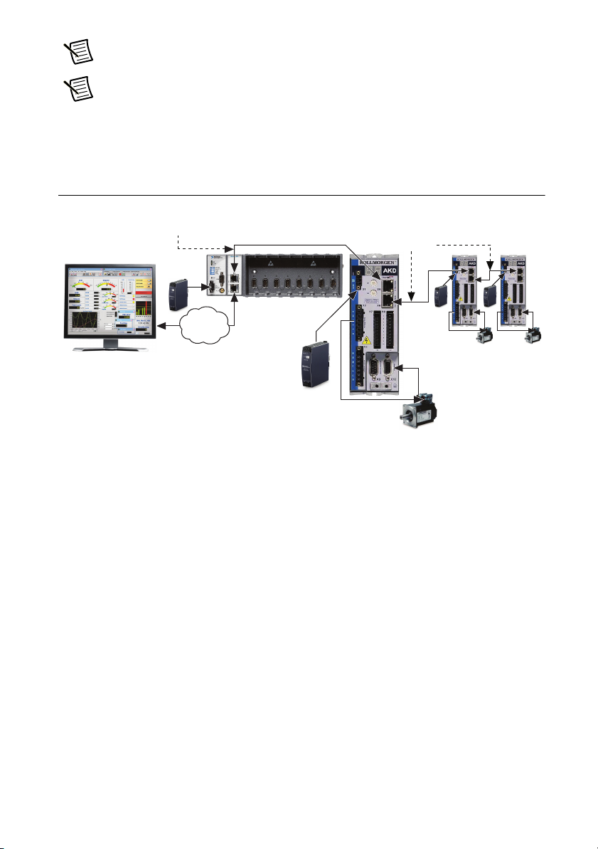
AKD EtherCAT
Servo Drive
NI RT Controller
(NI cRIO-9074 shown)
+24 V Power Supply
(NI PS-15 Shown)
Additional AKD
Servo Drives
(Optional)
EtherCAT Master
EtherCAT
EtherCAT
+24 V Power
Supply
EthernetEthernet
hardware drivers, go to
ni.com/info and enter Info Code ecatdriver.
Note Refer to the NI SoftMotion ReadMe to ensure the installed version of
NI-Industrial Communications for EtherCAT is compatible with your installation of
the NI SoftMotion module.
Figure 1 shows a simplified connection diagram.
Figure 1. AKD EtherCAT Servo Drive Connection Diagram
Related Documentation
The following documents contain additional information that you may find helpful. All
referenced documents ship with the product and are available at ni.com/manuals.
• AKD Installation Manual—Use this document to learn additional information about the
electrical and mechanical aspects of the AKD EtherCAT servo drive, including important
safety information.
• Documentation for the CompactRIO or PXI controller (shipped with the hardware and
available at ni.com/manuals).
• LabVIEW NI SoftMotion Module Help—Use this help file to learn about using the
NI SoftMotion Module in LabVIEW including information about programming with and
using the NI SoftMotion Module with LabVIEW. To access this help file from LabVIEW,
select Help»LabVIEW Help, then expand the LabVIEW NI SoftMotion Module book on
the Contents tab.
• NI Industrial Communications for EtherCAT software documentation.
Getting Started with AKD EtherCAT Drives and NI SoftMotion | © National Instruments | 3
Page 4
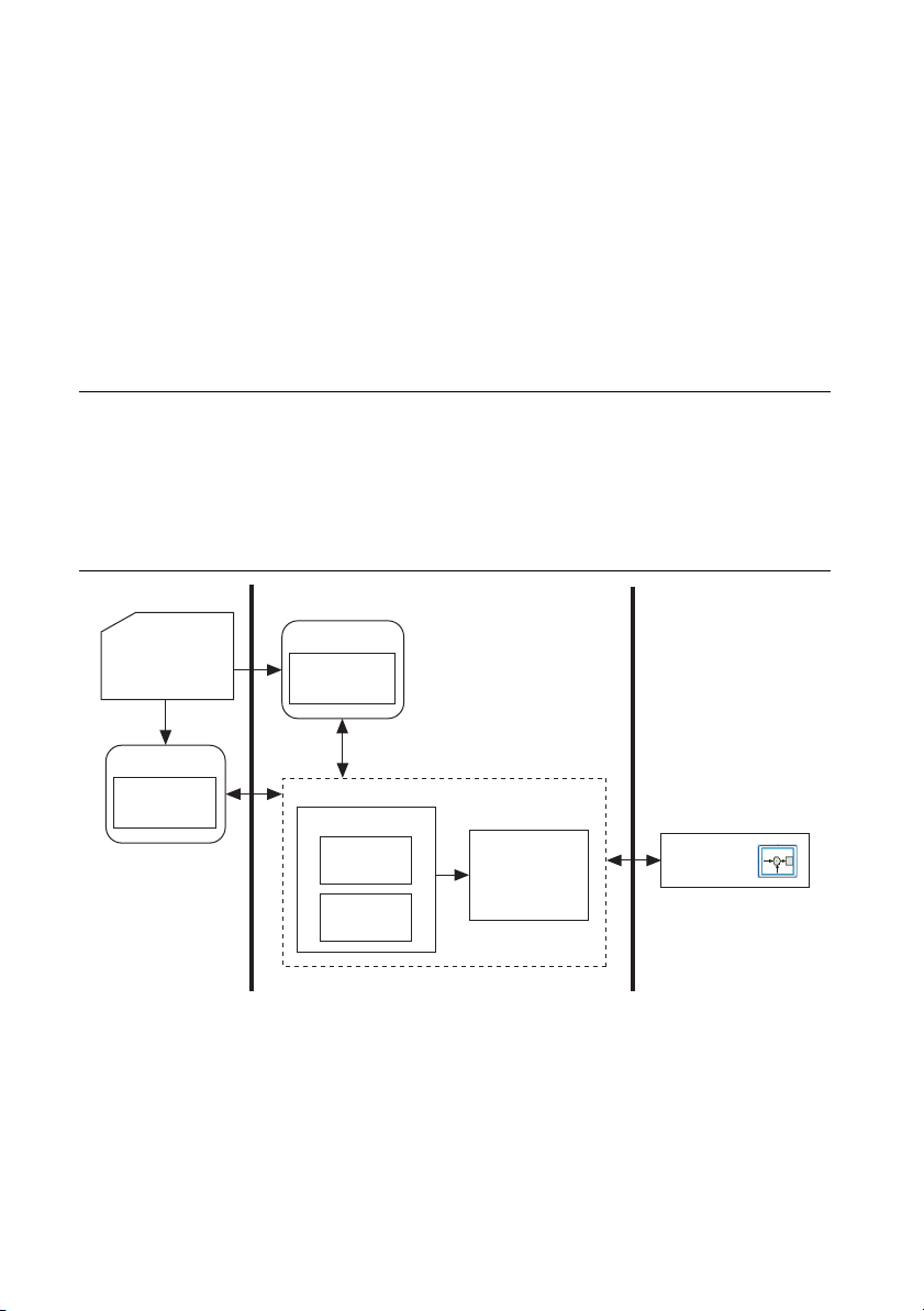
• LabVIEW Help—Use the LabVIEW Help to access information about LabVIEW
Motion Manager
Tr ajectory
Generator
Supervisory
Control
Host HMI and
Axis Settings:
LabVIEW Project
Windows RT Target
User VI
NI SoftMotion
APIs
NI SoftMotion
User VI
NI SoftMotion
APIs
EtherCAT
Drive
Communication
Module
EtherCAT
Drive
EtherCAT Drive
programming concepts, step-by-step instructions for using LabVIEW, and reference
information about LabVIEW VIs, functions, palettes, menus, tools, properties, methods,
events, dialog boxes, and so on. The LabVIEW Help also lists the LabVIEW documentation
resources available from National Instruments. Access the LabVIEW Help by selecting
Help»LabVIEW Help.
• Getting Started with the LabVIEW Real-Time Module—Use this document to learn how to
develop a real-time project and VIs, from setting up RT targets to building, debugging, and
deploying real-time applications. Access the Getting Started with the LabVIEW Real-Time
Module PDF by selecting Start»All Programs»National Instruments»LabVIEW»
LabVIEW Manuals»RT_Getting_Started.pdf.
NI SoftMotion Module Overview
The LabVIEW NI SoftMotion Module allows you to create deterministic motion control
applications using the LabVIEW Development System.
The following figure shows the NI SoftMotion Module architecture when you are using
NI SoftMotion with the AKD EtherCAT servo drive.
Figure 2. NI SoftMotion and AKD EtherCAT Servo Drive Architecture
4 | ni.com | Getting Started with AKD EtherCAT Drives and NI SoftMotion
Page 5

Use the LabVIEW Project to configure all your axis settings and test your configuration. When
your hardware configuration is complete, you use NI SoftMotion to create move profiles. Refer
to the NI SoftMotion Module Help, available by selecting Help»LabVIEW Help, for
information about using the NI SoftMotion Module to create motion applications. Use the
NI Example Finder to browse and search installed NI SoftMotion Module examples. Select
Help»Find Examples to launch the NI Example Finder.
Hardware and Software Configuration
This section covers the hardware and software setup for the EtherCAT master and
AKD EtherCAT servo drive, and contains instructions about using the NI SoftMotion Module
to configure and test your system.
Note This document uses a CompactRIO controller as the EtherCAT master. Refer
to Configuring a PXI or Industrial Controller Master for setup instructions for those
devices.
The following procedure assumes the device is configured with the factory default settings it
shipped with. If the device has been previously configured, use Kollmorgen WorkBench
software to restore it to the default settings before proceeding . Refer to th e Parameter Load/Save
topic in the Using Parameters and the Terminal Screen section of the Kollmorgen WorkBench
help for more information.
Getting Started with AKD EtherCAT Drives and NI SoftMotion | © National Instruments | 5
Page 6
Step 1: Set Up the CompactRIO System
1
4
3
5
2
Complete the following steps to set up the CompactRIO hardware.
1. Install the real-time CompactRIO controller on the chassis if you are not using an integrated
controller and chassis.
Note Write down the controller serial number before installing the controller onto
the chassis. You will be unable to read the serial number after you have mounted the
controller.
a. Make sure that no power is connected to the controller or the chassis.
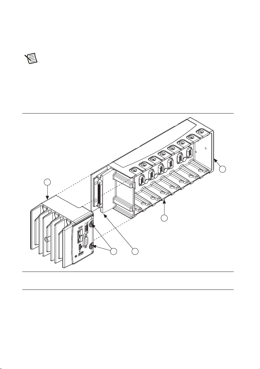
b. Align the controller with the chassis as shown in Figure 3.
Figure 3. Installing the Controller on the Chassis (Eight-Slot Chassis Shown)
1 Controller
2Captive Screws
3 Controller Slot
4 Reconfigurable Embedded Chassis
5 Grounding Screw
c. Slide the controller onto the controller slot on the chassis. Press firmly to ensure the
chassis connector and the controller connector are mated.
d. Using a number 2 Phillips screwdriver, tighten the two captive screws on the front of
the controller.
6 | ni.com | Getting Started with AKD EtherCAT Drives and NI SoftMotion
Page 7
2. Connect the controller to a power supply and an Ethernet network on the same subnet as
Additional
AKD EtherCAT Drive/Slave Devices
AKD EtherCAT Drive
NI Master Controller
Host
Computer
Secondary
Primary
IN (X5)
OUT (X6)
EtherCAT
Ethernet
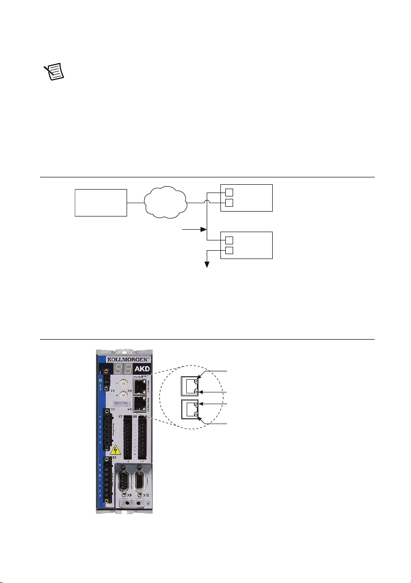
Not currently used
X5
X6
IN port link
(on = active, off = inactive)
Run
(on = running, off= not running)
OUT port link
(on = active, off = inactive)
the development computer. Refer to the controller operating instructions for information
about connecting the controller to the power supply and Ethernet network.
Note Do not plug in or turn on any power to the system until after all required
hardware connections are made.
3. Connect the secondary port of your EtherCAT Master directly to the X5 Motion Bus IN port
(top port) on the AKD EtherCAT servo drive using a standard Category 5 Ethernet cable.
The secondary port is the top port (LAN PORT #2). You may expand the deterministic
Ethernet network by connecting an additional AKD EtherCAT drive or other slave devices
to the X6 Motion Bus OUT port (bottom port) on the first AKD EtherCAT drive.
Figure 4. Connecting the AKD EtherCAT Drive to the Network
The LED indicators on the AKD Motion Bus IN and Motion Bus OUT ports display the
communication status. Figure 5 shows the LED indicators on the X5 and X6 connectors.
Figure 5. AKD X5 and X6 Motion Bus Connectors
Getting Started with AKD EtherCAT Drives and NI SoftMotion | © National Instruments | 7
Page 8
Step 2: Connect the AKD EtherCAT Drive
1
2
3
6
10
8
5
7
9
4
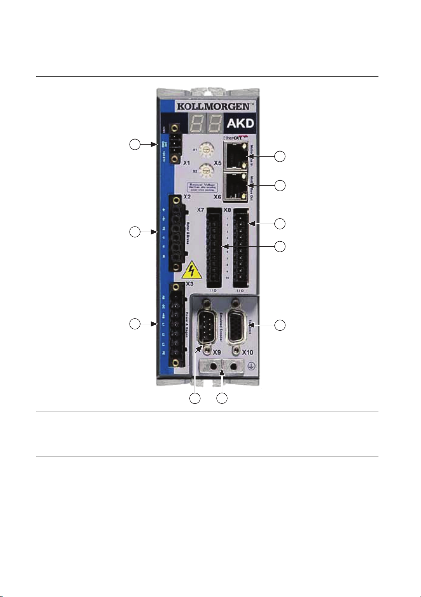
Figure 6 shows an overview of the connectors on the AKD EtherCAT servo drive.
Figure 6. AKD EtherCAT Servo Drive Connectors
1 24 V Supply, STO (X1)
2 Motor, Brake (X2)
3 AC Input Power (X3)
4 Encoder Emulation (X9)
5 Drive Grounding Lug
6 Feedback (X10)
7 I/O Connector (X7)
8 I/O Connector (X8)
9 Motion Bus OUT (X6)
10 Motion Bus IN (X5)
Mount the Drive and Connect the Protective Earth
1. Mount the drive to a conductive metal plate. Refer to the AKD Installation Manual for
dimensions and additional information specific to the drive model.
2. Connect the protective earth (PE) to either ground screw on the drive grounding lug.
Figure 6 shows the location of the grounding lug on the drive.
8 | ni.com | Getting Started with AKD EtherCAT Drives and NI SoftMotion
Page 9
Connect the Logic Power Supply to the X1 Connector
The +24 V power supply provides the logic power to the AKD EtherCAT servo drive. Complete
the following steps to connect the +24 V power supply to the drive.
Note Do not plug in or turn on the +24 V power supply until all required hardware
connections are made.
1. Connect the +24 V power supply (+) terminal to the +24 terminal on the AKD X1
connector.
2. Connect the +24 V power supply return (-) terminal to the GND terminal on the AKD X1
connector.
3. Connect the STO terminal and GND terminal to the output of a safety relay or security
control. The safety relay must comply with the requirements of the SIL 2 according to
IEC 61800-5-2, PL d according to ISO 13849-1, or Category 3 according to EN-954. Refer
to the AKD Installation Manual for more information.
Note If the STO functionality is not required, connect the STO terminal directly to
the +24 terminal on the AKD X1 connector to bypass any external safety circuitry.
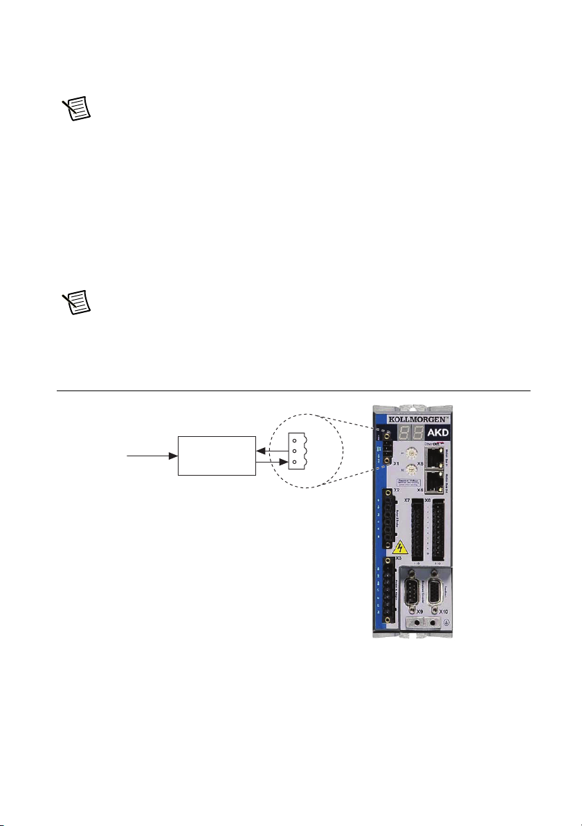
Figure 7 shows the AKD EtherCAT servo drive X1 connector pinout.
Figure 7. AKD X1 Connector
+24
Interlock
Safety Relay
or
Security Control
1
2
GND
3
STO
Connect the Hardware Enable on the X8 Connector
The Enable input (X8, pin 4) requires external connection to enable the output stage on the drive.
The enable signal allows either a sinking or sourcing configuration. Refer to Figure 9 for the X8
connector pinout. Refer to Chapter 8, Electrical Installation, in the AKD Installation Manual for
connection information.
Getting Started with AKD EtherCAT Drives and NI SoftMotion | © National Instruments | 9
Page 10

Connect the Motor and Encoder to the AKD Drive
1
2
All AKM series servo motors available from NI come pre-wired for direct connection to the
AKD EtherCAT servo drive X2 Motor connector and X10 Feedback connector. Figure 8 shows
the location of the connectors.
1. Connect the motor 6-pin connector to the AKD EtherCAT servo drive X2 Motor connector.
Note The X2 connector also provides connection for the drive to control the +24 V
holding brake for motors that have a brake. Refer to the AKD Installation Manual for
information about the holding brake if your motor contains an internal brake.
2. Connect the motor DSUB feedback connector to the AKD EtherCAT servo drive X10
Feedback connector.
Figure 8. Motor and Encoder Connections
1 Motor Connector (X2) 2 Feedback Connector (X10)
10 | ni.com | Getting Started with AKD EtherCAT Drives and NI SoftMotion
Page 11

Connect Additional I/O On the X7 and X8 Connectors
1
2
3
4
5
6
7
8
9
10
1
2
3
4
5
6
7
8
9
10
X7 Connector X8 Connector
DCOM X7
DI7
DI4
DI3
DO2–
DO2+
DO1+
DO1–
DI2
DI1
Fault
Fault
DCOM X8
Enable
DI6
DI5
AO+
AGND
AI–
AI+
Use the AKD X7 and X8 connectors to connect additional I/O such as limit switches, position
capture inputs, or other I/O as required by your application. Refer to the AKD Installation
Manual for information about connecting digital input and output devices to the AKD EtherCAT
servo drive. Figure 9 shows the X7 and X8 connector pinout.
Figure 9. AKD X7 and X8 Connectors
NI SoftMotion digital inputs and outputs are 0-based, while the digital inputs and outputs
on the AKD EtherCAT servo drive are 1-based. This means that Digital Input 1 on the AKD
corresponds to DI0 in the NI SoftMotion software. Table 1 shows the preset signal mapping for
the AKD EtherCAT servo drive in the NI SoftMotion software.
Table 1. AKD to NI SoftMotion Signal Mapping
AKD Connector Terminal NI SoftMotion Pin Signal Mapping
DI1 (X7 pin 10) DI0 Home
DI2 (X7 pin 9) DI1 Capture
DI3 (X7 pin 4) DI2 Forward Limit
DI4 (X7 pin 3) DI3 Reverse Limit
You can connect the AKD EtherCAT servo drive to sourcing or sinking digital output devices
depending on how the DCOM terminal on each connector is wired.
• Sourcing—Connect DCOM to the negative terminal on the +24 V supply.
• Sinking—Connect DCOM to the positive terminal on the +24 V supply.
Getting Started with AKD EtherCAT Drives and NI SoftMotion | © National Instruments | 11
Page 12

Connect the AC Input Power
1
2
3
4
5
6
7
–RB
–DC
+RB
L1
L2
L3
PE
DC
Out
L1
User-Provided
Filter
(optional)
L2
L3
AKD Servo Drive
Protective
Earth
L1
L2
L3
Protective
Earth
Connect the X3 mains supply connector to AC input power. Pins 4 through 7 contain the AC
power signals. The X3 connector also provides signals for an external brake (regen) resistor
(±RB) and DC bus link (-DC). Refer to the AKD Installation Manual for information about using
these terminals.
Note Do not turn on AC power until all required hardware connections are made.
Figure 10 shows the location and pin assignment for the X3 connector.
Figure 10. AKD EtherCAT Servo Drive X3 Connector
AC input power can be connected for either a three-phase or single-phase operation.
Figure 11 shows three-phase connection.
12 | ni.com | Getting Started with AKD EtherCAT Drives and NI SoftMotion
Note External filtering and fusing are optionally provided by the user. Refer to the
AKD Installation Manual for information about filter and fuse requirements.
Figure 11. AC Input Power Three-Phase Connection
Page 13

Figure 12 shows single-phase connection.
L1
User-Provided
Filter
(optional)
L2
L3
L1
Neutral (L2)
Protective
Earth
Protective
Earth
DC
Out
AKD Servo Drive
Figure 12. AC Input Power Single-Phase Connection
Confirm Drive Connections
After all hardware connections have been made complete the following steps to confirm the
AKD hardware setup.
1. Power on the RT controller.
2. Apply AC power to the AKD drive.
3. Turn on the +24 V power supply. After logic power is supplied to the drive, the drive
displays the following sequence of flashes in the LED indicators.
a. - -
b. []
c. Drive IP address, flashed sequentially
d. Drive status, either the operation mode or the fault or warning code if there is a fault
or warning condition. The operation modes are as follows:
• o0—torque mode (current mode)
• o1—velocity mode
• o2—position mode
Note If the drive shows a fault or warning code, refer to the AKD Fault and
Warning Messages Card that came with the drive or the NI SoftMotion Module Help
for more information about the fault or warning, including possible solutions. You
can use the Interactive Test Panel dialog box or the Clear Faults method to clear the
drive faults. AKD drive warnings are only displayed on the drive LED indicators and
are not available through NI SoftMotion.
Getting Started with AKD EtherCAT Drives and NI SoftMotion | © National Instruments | 13
Page 14

Step 3: Install Software on and Configure the NI RT Controller
Complete the following steps to configure the controller and install software on it.
1. Launch Measurement & Automation Explorer (MAX) on the development computer by
clicking the NI MAX icon on the desktop, or by selecting Start»All Programs»National
Instruments»NI MAX
2. Select the controller under Remote Systems in the Configuration pane. If you do not see
the controller, you may need to disable the firewall on the development computer.
3. Verify that the Serial Number in the Identification section matches the serial number on
the device.
4. If you are using a PXI controller or you do not want to format the disk on the controller,
eliminating all installed software and files, power on the controller and skip to step 9.
Note If you need to format the PXI controller, refer to the Measurement &
Automation Explorer Help for instructions.
5. Set the Safe Mode switch on the controller to the On position.
6. Power on the controller. If it is already powered on, press the Reset button on the controller
to reboot it.
7. Right-click the controller under Remote Systems in the Configuration pane and select
Format Disk. Click Yes on the dialog box that appears.
8. When MAX finishes formatting the disk, set the Safe Mode switch to the Off position and
press the Reset button on the controller to reboot it.
9. Select the System Settings tab and type a descriptive name for the system in the Name
field.
10. (Optional) Complete this step only if the target has an empty IP address (0.0.0.0). Select the
Network Settings tab and select DHCP or Link Local from the Configure IPv4 Address
list to assign an IP address or select Static to specify a static IP address in the IPv4 Address
section.
11. Click Save on the toolbar and let MAX reboot the system.
12. When the new system name appears under Remote Systems, expand the controller item in
the tree, right-click Software, and select Add/Remove Software.
13. Select a recommended software set that i ncl ude s NI -RI O 3. 5.0 or later with NI Scan Engine
Support and the following add-ons enabled:
• LabVIEW NI SoftMotion Module
• NI-Industrial Communication for Ethercat
14 | ni.com | Getting Started with AKD EtherCAT Drives and NI SoftMotion
Page 15

14. Click Next to install the selected software on the controller. Click Help if you need
information about installing recommended software sets.
15. When MAX finishes installing the software on the controller, select the controller under
Remote Systems in the Configuration pane.
16. Click the Network Settings tab and expand More Settings in the eth1 section.
17. Select EtherCAT from the Adapter Mode list.
Note These settings are not available if NI-Industrial Communications for
EtherCAT is not installed to the target.
18. Some RT controllers can configure the Packet Detection of the Ethernet Adapter. If the
option is available for your target, in the eth0 (Primary) section click More Settings and
change Packet Detection to Polling. Leave the Polling Interval at 1 ms.
When you have completed these steps the Network Settings tab will look similar to
Figure 13.
Figure 13. Network Settings Tab
19. Click Save.
20. Reboot the controller when prompted.
21. Close MAX.
Getting Started with AKD EtherCAT Drives and NI SoftMotion | © National Instruments | 15
Page 16

Step 4: Creating a Project and Adding an NI SoftMotion Axis
Complete the following steps to create a LabVIEW project and add an NI SoftMotion axis
associated with the AKD EtherCAT servo drive.
1. Launch LabVIEW.
2. Select File»Create Project or Project»Create Project to display the Create Project
dialog box. You can also click the Create Project button on the Getting Started window.
The Create Project dialog box includes a list of templates and sample project you can use
to ensure that the project you create uses reliable designs and programming practices.
3. Select Blank Project from the list of templates.
4. Click Finish.
5. Select Help and make sure that Show Context Help is checked. You can refer to the
context help throughout the tutorial for information about items on the block diagram.
6. Right-click the top-level project item in the Project Explorer window and select New»
Targets and Devices from the shortcut menu to display the Add Targets and Devices
dialog box.
7. Make sure that the Existing target or device radio button is selected.
8. Expand Real-Time CompactRIO, Real-Time PXI, or Real-Time Industrial Controller
as appropriate for your hardware.
9. Select the controller to add to the project and click OK.
10. Complete the following additional steps if you are using a CompactRIO controller.
a. If you have LabVIEW FPGA installed, the Select Programming Mode dialog box
appears. Select Scan Interface to put the system into Scan Interface mode.
Tip Use the CompactRIO Chassis Properties dialog box to change the
programming mode in an existing project. Right-click the CompactRIO chassis in the
Project Explorer window and select Properties from the shortcut menu to display
this dialog box.
b. Click Continue.
11. In the LabVIEW Project Explorer window, right-click the master controller and select
New»Targets and Devices.
16 | ni.com | Getting Started with AKD EtherCAT Drives and NI SoftMotion
Page 17

12. In the
Add Targets and Devices
or device
and expand the category EtherCAT Master Device to auto-discover the EtherCAT
dialog window shown in Figure 14, select
Existing target
port on the master controller. Click OK to add the master. It will automatically try to discover
any connected EtherCAT slaves. An EtherCAT master device can be added manually at any
time.
Figure 14. Adding the EtherCAT Master
Note When all the slave devices are discovered, the LabVIEW Project Explorer
window lists each slave device and any installed C Series modules. If the AKD
EtherCAT drive does not appear in the Project Explorer window after this step,
confirm that the NI Scan Engine is in Configuration mode and repeat steps 11 and 12.
Refer to the Tips and Troubleshooting section for more information.
13. Right-click the controller item in the Project Explorer window and select Properties from
the shortcut menu to display the RT Target Properties dialog box. Select Scan Engine
from the Category list to display the Scan Engine page.
14. Set the Scan Period to 8 ms or lower, then click OK to close the RT Target Properties
dialog box.
Note The Scan Period setting is used to determine the AKD EtherCAT drive
Cycle time and Cycle exp settings, ignoring any values in the EtherCAT:
Advanced:Initial Commands dialog box in the LabVIEW Project. These settings
must match for proper communication between the drive and the EtherCAT master.
Getting Started with AKD EtherCAT Drives and NI SoftMotion | © National Instruments | 17
Page 18

15. Right-click the controller item in the Project Explorer window and select New»
NI SoftMotion Axis from the shortcut menu to open the Axis Manager dialog box, shown
in Figure 15.
Figure 15. Axis Manager Dialog Box
16. Click Add New Axis to create an NI SoftMotion axis associated with the AKD EtherCAT
drive. Axes are automatically bound to an available drive. You can double-click the axis
name to rename the axis and give it a descriptive name.
17. Click OK to close the Axis Manager dialog box. The new axis is added to the Project
Explorer window.
Note You cannot associate more than one axis with the same AKD EtherCAT drive.
When you have finished these steps your LabVIEW project should look similar to the
image in Figure 16.
Figure 16. Project Explorer Window with AKD EtherCAT Servo Drive Axis
18 | ni.com | Getting Started with AKD EtherCAT Drives and NI SoftMotion
Page 19

Step 5: Install Kollmorgen WorkBench and Configure the Drive
Kollmorgen WorkBench is available on the CD that came with the AKD servo drive and is also
available from ni.com/updates. Complete the following steps to install Kollmorgen
WorkBench.
1. Insert the KollMorgen WorkBench CD in the CD-ROM drive.
2. Double-click
3. Follow the onscreen instructions to complete the installation.
Complete the following steps to configure the drive settings with Kollmorgen WorkBench.
1. Launch the Kollmorgen WorkBench software by clicking the Kollmorgen WorkBench icon
on the desktop ( ), or by selecting Start»All Programs»Kollmorgen»
Kollmorgen WorkBench.
2. Select the drive to configure from the list and click Connect.
Full Setup.exe to launch the installer.
Note If the drive is not in the list, refer to the Configuring a PXI or Industrial
Controller Master section of this document for possible solutions.
Getting Started with AKD EtherCAT Drives and NI SoftMotion | © National Instruments | 19
Page 20

Figure 17 shows the Kollmorgen WorkBench Start page.
1
32
Figure 17. Kollmorgen WorkBench Start Page
1 Available Drives 2 Specify Address 3 Connect to Drive
20 | ni.com | Getting Started with AKD EtherCAT Drives and NI SoftMotion
Page 21

3. Open the Parameter Load/Save page from the configuration tree and click Factory
Defaults to return the drive settings to the factory default values. Any drive settings not
updated in this document are assumed to be the default values.
4. (Optional) Change the name of the drive from the default name of
Overview page to a more descriptive name.
Figure 18 shows the AKD Overview page.
Figure 18. Kollmorgen WorkBench Overview Page
1
2
3
4
5
no_name on the AKD
6
7 8 109
1 Software Enable/Disable
2 Command Source
3 Operation Mode
4 Clear Faults
5 Save Configuration Settings to Drive
Getting Started with AKD EtherCAT Drives and NI SoftMotion | © National Instruments | 21
6 Software Enable/Disable
7 Drive Active Indicator
8 Software Enable Status Indicator
9 Hardware Enable Status Indicator
10 Fault Indicator
Page 22

Step 6: Tune the System using Kollmorgen WorkBench
In this section you will tune the axis associated with your AKD EtherCAT servo drive using the
Kollmorgen WorkBench.
Kollmorgen WorkBench is software provided by Kollmorgen that allows you to configure your
AKD servo drive, such as maximum motor current, encoder resolution, and I/O scaling. For
information about tuning the drive with WorkBench, refer to the Tuning Your System topic in the
installed Kollmorgen WorkBench Help.
Step 7: Configure the AKD EtherCAT Servo Drive Axis
In this section you will configure the axis associated with your AKD EtherCAT servo drive
using the Axis Configuration dialog box.
Complete the following steps to configure the axis I/O settings for use with the AKD EtherCAT
servo drive.
1. Right-click the axis in the Project Explorer window and select Properties from the
shortcut menu to open the Axis Configuration dialog box.
Figure 19 shows the parts of the Axis Configuration dialog box for AKD EtherCAT servo
drives.
22 | ni.com | Getting Started with AKD EtherCAT Drives and NI SoftMotion
Page 23

Figure 19. Axis Configuration Dialog Box for AKD EtherCAT Servo Drives
2. On the General Settings page, confirm that the Axis Enabled checkbox contains a
checkmark and that the Enable Drive on Transition to Active Mode checkbox does not
contain a checkmark.
3. On the General Settings page, in the Deployment section, there is an option to deploy
configured settings to the drive. This is unselected by default, as the default drive settings
work well for most applications. When selected, the drive settings will be overwritten by
the Velocity Loop settings, Position Loop gains, and Brake settings configured with the
Axis Configuration dialog box. National Instruments recommends leaving this option
unselected and using WorkBench to configure the drive. Refer to Step 5: Install Kollmorgen
WorkBench and Configure the Drive for more information.
Note The Position Error Limit, set on the Position Loop page, will always be
deployed to the drive regardless of your deployment selection.
Getting Started with AKD EtherCAT Drives and NI SoftMotion | © National Instruments | 23
Page 24

4. Complete the following additional steps if you do not have limits and home connected at
this time:
a. Click the Limits & Home button.
b. Clear the Enable checkbox in the Forward Limit, Reverse Limit, and Home Switch
sections.
Note These configuration settings disable limits for initial setup and testing
purposes. National Instruments recommends connecting and enabling limits in your
final application.
5. Click the Encoder button and set the display Units for the application. For initial setup, set
the Units to revand Counts per Unit to 1,048,576.
Note Regardless of the type of feedback or custom scaled units in Kollmorgen
WorkBench, the AKD will scale the EtherCAT feedback to 2^20 (or 1,048,576)
counts per revolution. If a linear permanent magnet motor is used, the units will be
2^20 counts per magnetic pole pitch. This configuration can be used to set any
custom unit by changing the counts per unit value.
6. Configure any additional I/O settings according to your system requirements.
7. Click OK to close the Axis Configuration dialog box.
Caution Make sure all hardware connections are made and power is turned on
before deploying the project. Deployment may switch the NI Scan Engine to Active
mode. Refer to the Deploying and Running VIs on an RT Target topic in the
LabVIEW Help for more information about deployment and for troubleshooting tips.
8. Right-click the controller item in the Project Explorer window and select Deploy All to
deploy the axis information.
9. Select File»Save Project to save the project.
Step 8: Enable and Test the Drive using LabVIEW
Use the Interactive Test Panel to test and debug your motion system and configuration settings
on the selected axis. With the Interactive Test Panel you can perform a simple straight-line
move, monitor feedback position and position error information, I/O and move status
information, change move constraints, get information about software errors and faults,
and view position or velocity plots of the move.
Caution The test parameters in this steps assume that the units have been scaled to
revolutions as described in the preceeding step. If the motor is already connected to
a mechanical system, ensure that moving the motor shaft for 10 revolutions at
1 revolution per second will not damage any components.
24 | ni.com | Getting Started with AKD EtherCAT Drives and NI SoftMotion
Page 25

Complete the following steps to test your setup after configuring and tuning the axis.
Additional
AKD EtherCAT Drive/Slave Devices
AKD EtherCAT Drive
NI Master Controller
Host
Computer
Secondary
Primary
IN (X5)
OUT (X6)
EtherCAT
Ethernet
1. Right-click the axis in the Project Explorer window and select Interactive Test Panel
from the shortcut menu. Opening this dialog box sends the axis settings to the hardware and
activates the I/O on the module.
2. On the Move tab, set the Target Position to 10.
3. On the Move Constraints tab, configure the following settings:
a. Set Velocity to
1.00 Rev/sec
b. Set Acceleration to 10.00 Rev/sec^2
c. Set Deceleration to
d. Set Acceleration Jerk to
10.00 Rev/sec^2
100.00 Rev/sec^3
e. Set Deceleration Jerk to 100.00 Rev/sec^3
4. Click the Start button on the bottom of the dialog box. The move should proceed for
10 revolutions at a velocity of 1 revolution per second.
5. Use the Status and Plots tabs to monitor the move while it is in progress.
Your system is now configured and ready for motion application development.
Configuring a PXI or Industrial Controller Master
Complete the following steps to use a PXI or Industrial Controller as the EtherCAT master.
1. Connect the controller to an Ethernet network on the same subnet as the development
computer. Refer to the controller operating instructions for information about wiring
the controller to the power supply and Ethernet network.
2. Connect the secondary port of your EtherCAT Master directly to the IN port (top port) on
the AKD EtherCAT servo drive using a standard Category 5 Ethernet cable. You may
expand the deterministic Ethernet network by connecting an additional AKD EtherCAT
drive or other slave devices to the OUT port (bottom port) on the first AKD EtherCAT
drive.
Figure 20. Connecting the AKD EtherCAT Drive to the Network
Getting Started with AKD EtherCAT Drives and NI SoftMotion | © National Instruments | 25
Page 26

Note Do not plug in or turn on any power to the system until after all required
Not currently used
X5
X6
IN port link
(on = active, off = inactive)
Run
(on = running, off= not running)
OUT port link
(on = active, off = inactive)
hardware connections are made.
The LED indicators on the AKD Motion Bus IN and Motion Bus OUT ports display the
communication status. Figure 5 shows the LED indicators on the X5 and X6 connectors.
Figure 21. AKD X5 and X6 Motion Bus Connectors
3. Install software on the RT target as described in Step 3: Install Software on and Configure
the NI RT Controller.
4. Disable Legacy USB Support in the PXI master PC BIOS, if it is enabled.
Tips and Troubleshooting
The Drive Does Not Enable
If, after going through all steps in this document, the AKD EtherCAT servo drive does not
enable, verify the following settings:
• Make sure that the hardware enable is connected to the +24 V power supply as described
in Connect the Hardware Enable on the X8 Connector.
• The software enable must be enabled. Verify that the NI Scan Engine is in active mode and
th at D riv e En abl e is act ive . You can u se t he Interactive Test Panel dialog box or the Power
function to enable the drive.
• The drive must not be in a fault state. You can use the Interactive Test Panel dialog box
or the Clear Faults function to clear the drive faults.
Tip Refer to the AKD Fault and Warning Messages card that came with the drive
or the NI SoftMotion Module Help for fault information and solutions.
26 | ni.com | Getting Started with AKD EtherCAT Drives and NI SoftMotion
Page 27

The Axis Does Not Appear To Move
The AKD will scale the EtherCAT feedback to 2^20 (or 1,048,576) counts per revolution. If a
linear permanent magnet motor is used, the units will be 2^20 counts per magnetic pole pitch.
Ensure that the move parameters in the Interactive Test Panel and encoder feedback scaling in
the Axis Configuration dialog box are consistent.
NI SoftMotion features multiple Axis Control Modes (position, velocity, torque, or automatic
mode). An axis will not respond to commands from the interactive test panel if it is not in the
corresponding mode. If your axis does not appear to move, use the Axis Control Mode property
to change the control mode. For more information, refer to the NI SoftMotion Help.
The Drive Is Not Automatically Added to the LabVIEW Project
The NI Scan Engine must be in Configuration mode to detect and add EtherCAT slave devices
to the EtherCAT bus. Complete the following steps to check and switch the NI Scan Engine
mode:
1. Right-click the EtherCAT master and select View in System Manager from the shortcut
menu.
2. In the Scan Engine Mode section, check the Scan Engine mode.
• If the Scan Engine mode is Active, click the Change to Configuration button and
attempt to add the AKD EtherCAT servo drive again.
• If the Scan Engine mode is Fault, click the Clear All Faults button in the Faults
section, then click the Change to Configuration button and attempt to add the AKD
EtherCAT servo drive again.
The Drive Returns a Synchronization Fault or Warning
Verify the following settings if the AKD EtherCAT drive returns fault or warning code 125
(Synchronization Lost):
• Check the EtherCAT input connection (X5).
• Use a shielded ethernet cable (FTP/STP) for the EtherCAT master to AKD drive
connection.
• Confirm that the NI Scan Engine scan period is 8 ms or lower.
Getting Started with AKD EtherCAT Drives and NI SoftMotion | © National Instruments | 27
Page 28

Wiring Diagram
Figure 22. AKD Wiring Diagram
Reference Safety Instructions
and Use As Directed
Feedback
M
W1
Regeneration
Resistor
Filter
Mains
Contactor
FN1FN2F
N3
Thermal Control
Included
B–
B+
PE
U1
V1
F
B1
F
B2
+–
Supply Unit
24V DC
FH1FH2F
H3
1
2
3
4
5
6
1
2
3
4
5
6
7
1
3
2
Feedback
– Br
+ Br
PE
U
V
W
– RB
– DC
+ RB
L1
L2
L3
PE
+ 24V
STO
GND
(
+ DC
X2
X3
)
X1
X7X10
DIGITAL–IN7
DIGITAL–IN4
DIGITAL–IN3
DIGITAL–OUT2
DIGITAL–OUT2
DIGITAL–OUT1
DIGITAL–OUT1
DIGITAL–IN2
DIGITAL–IN1
X8
Fault
ENABLE
DIGITAL–IN6
(NSTOP)
DIGITAL–IN5
(PSTOP)
Analog–Out +
Analog–In –
Analog– In +
X5
Motion Bus In
X6
Motion Bus Out
X9
Encoder
Emulation
DGND
DGND
AGND
Control
+ 24V Referred
1
2
3
4
5
–
6
+
7
–
8
+
9
10
1
2
3
4
5
6
7
8
9
10
8
8
9
to I/O GND
I/O–GND
I/O–GND
–
+
–
+
+
Digital2
Digital1
Emergency
Stop Circ
uit
+
+ 24V Referred
to I/O GND
Tachometer
Vol tage
+/– 10V
+/– 10V Speed
Setpoint
Referred to
I/O–GND
Participant
Participant
Encoder
Evaluation
X11
TCP/IP
L1 L2 L3 PE
28 | ni.com | Getting Started with AKD EtherCAT Drives and NI SoftMotion
8
PE–Connection (Protective Earth)
Chassis Ground Connection (Panel)
Shield Connection Via Plug
Service
Page 29

Worldwide Support and Services
The NI website is your complete resource for technical support. At ni.com/support you have
access to everything from troubleshooting and application development self-help resources to
email and phone assistance from NI Application Engineers.
ni.com/services for NI Factory Installation Services, repairs, extended warranty, and
Vis it
other services.
ni.com/register to register your NI product. Product registration facilitates technical
Vis it
support and ensures that you receive important information updates from NI.
A Declaration of Conformity (DoC) is ou r cl aim o f com plia nce with the Council of the European
Communities using the manufacturer’s declaration of conformity. This system affords the user
protection for electromagnetic compatibility (EMC) and product safety. You can obtain the DoC
for your product by visiting
you can obtain the calibration certificate for your product at ni.com/calibration.
NI corporate headquarters is located at 11500 North Mopac Expressway, Austin, Texas,
78759-3504. NI also has offices located around the world. For telephone support in the United
States, create your service request at
For telephone support outside the United States, visit the Worldwide Offices section of
ni.com/niglobal to access the branch office websites, which provide up-to-date contact
information, support phone numbers, email addresses, and current events.
ni.com/certification. If your product supports calibration,
ni.com/support or dial 1 866 ASK MYNI (275 6964).
Getting Started with AKD EtherCAT Drives and NI SoftMotion | © National Instruments | 29
Page 30

Refer to the NI Trademarks and Logo Guidelines at ni.com/trademarks for more information on NI trademarks. Other product and company
names mentioned herein are trademarks or trade names of their respective companies. For patents covering NI products/technology, refer to the
appropriate location: Help»Patents in your software, the patents.txt file on your media, or the National Instruments Patents Notice at
ni.com/patents. You can find information about end-user license agreements (EULAs) and third-party legal notices in the readme file for your
NI product. Refer to the Export Compliance Information at ni.com/legal/export-compliance for the NI global trade compliance policy
and how to obtain relevant HTS codes, ECCNs, and other import/export data. NI MAKES NO EXPRESS OR IMPLIED WARRANTIES AS TO THE
ACCURACY OF THE INFORMATION CONTAINED HEREIN AND SHALL NOT BE LIABLE FOR ANY ERRORS. U.S. Government Customers: The data
contained in this manual was developed at private expense and is subject to the applicable limited rights and restricted data rights as set forth in
FAR 52.227-14, DFAR 252.227-7014, and DFAR 252.227-7015.
© 2010–2018 National Instruments. All rights reserved.
375592F-01 Oct18
 Loading...