

Page 1

Artisan Technology Group is your source for quality
new and certied-used/pre-owned equipment
• FAST SHIPPING AND
DELIVERY
• TENS OF THOUSANDS OF
IN-STOCK ITEMS
• EQUIPMENT DEMOS
• HUNDREDS OF
MANUFACTURERS
SUPPORTED
• LEASING/MONTHLY
RENTALS
• ITAR CERTIFIED
SECURE ASSET SOLUTIONS
SERVICE CENTER REPAIRS
Experienced engineers and technicians on staff
at our full-service, in-house repair center
Instra
Remotely inspect equipment before purchasing with
our interactive website at www.instraview.com
Contact us: (888) 88-SOURCE | sales@artisantg.com | www.artisantg.com
SM
REMOTE INSPECTION
View
WE BUY USED EQUIPMENT
Sell your excess, underutilized, and idle used equipment
We also offer credit for buy-backs and trade-ins
www.artisantg.com/WeBuyEquipment
LOOKING FOR MORE INFORMATION?
Visit us on the web at www.artisantg.com for more
information on price quotations, drivers, technical
specications, manuals, and documentation
Page 2
USER GUIDE AND SPECIFICATIONS
NI 9792 WSN Real-Time Gateway
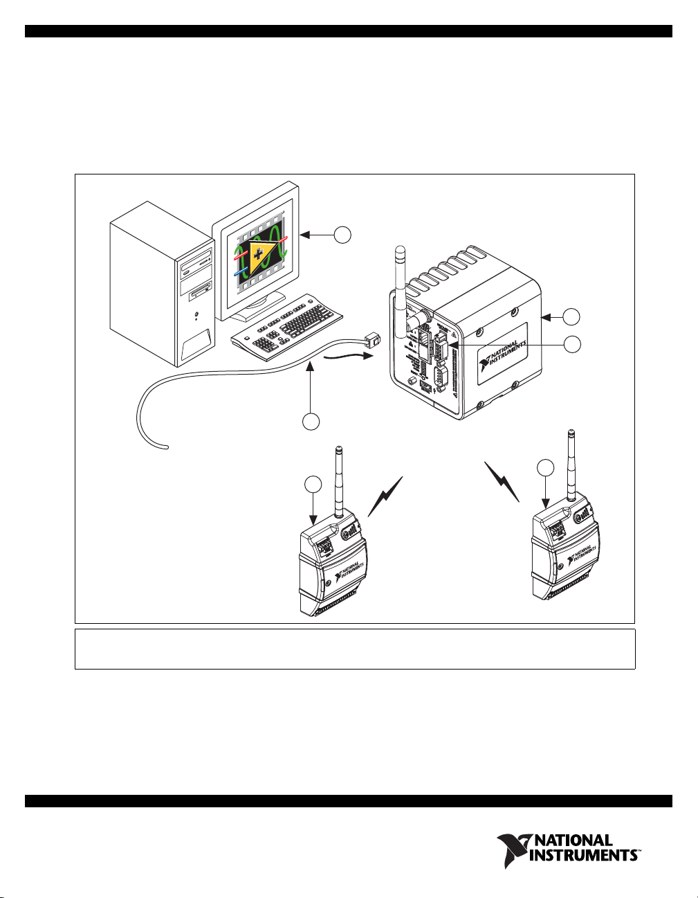
This user guide describes how to use the NI 9792 Wireless Sensor Network Real-Time Gateway and lists
specifications. The NI 9792 WSN Real-Time Gateway combines with NI WSN-32xx nodes to form a
wireless sensor network. Figure 1 shows the NI WSN system components.
1
5
2
3
1 PC or NI Real-Time Hardware Running
Application Software
2 NI 9792 WSN Real-Time Gateway
4
3 9–35 VDC Power Supply Connection
4 NI WSN-32xx Nodes
5 Ethernet Cable/Connection
Figure 1. NI WSN System Components
4
Page 3
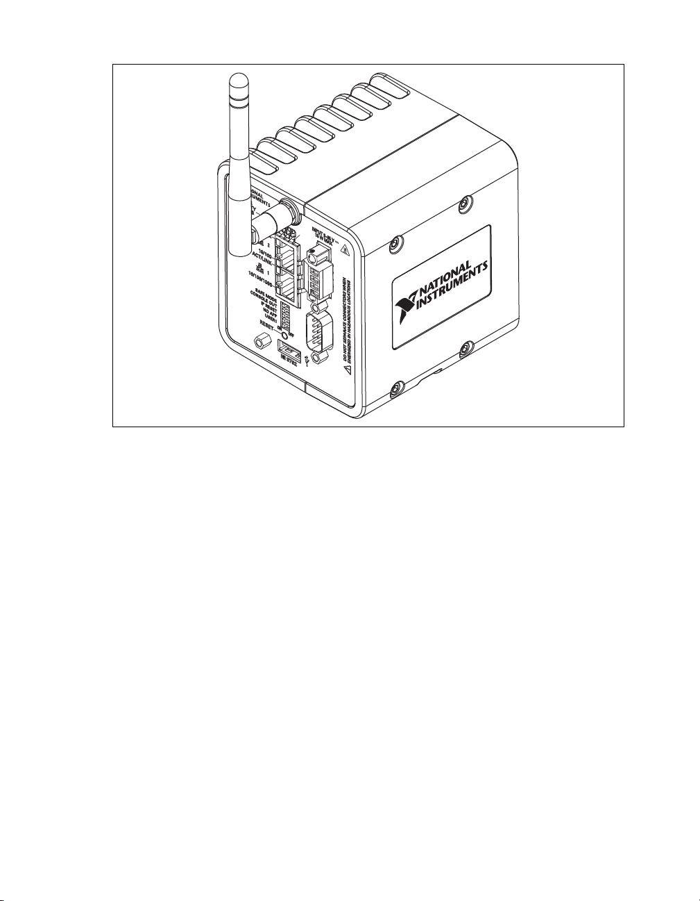
The NI 9792 WSN Real-Time Gateway is shown in Figure 2.
Figure 2. NI 9792 WSN Real-Time Gateway
NI 9792 WSN Real-Time Gateway User Guide and Specifications 2 ni.com
Page 4
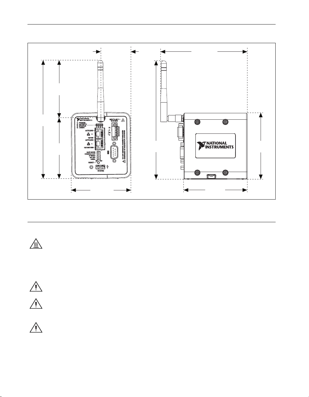
Dimensions
Figure 3 shows the NI 9792 WSN Real-Time Gateway device dimensions.
83 mm
(3.268 in.)
170.55 mm
(6.715 in.)
87.56 mm
(3.447 in.)
Safety Guidelines
43.47 mm
(1.712 in.)
170.55 mm
(6.715 in.)
86.25 mm
(3.396 in.)
124.84 mm
(4.915 in.)
91.38 mm
(3.598 in.)
Figure 3. NI 9792 WSN Real-Time Gateway Device Dimensions
95.63 mm
(3.765 in.)
Operate the NI 9792 WSN Real-Time Gateway only as described in this user guide.
Hot Surface This icon denotes that the component may be hot. Touching this component may result
in bodily injury.
NI WSN Safety Information
The following section contains important safety information that you must follow when installing and
using NI WSN products.
Caution Do not substitute parts or modify the NI WSN product. Use the product only with the
devices, accessories, and cables specified in the installation instructions.
Caution Do not operate a NI WSN products in an explosive atmosphere or where there may be
flammable gases or fumes. If you need to operate NI WSN products in such an environment, the
NI WSN products must be in a suitably rated enclosure.
Caution If you need to clean a NI WSN product, use a dry towel. The product must be completely
dry and free from contaminants before you return it to service.
NI 9792 WSN Real-Time Gateway User Guide and Specifications 3 ni.com
Page 5
Caution Operate the product only at or below Pollution Degree 2. Pollution is foreign matter in a
solid, liquid, or gaseous state that can reduce dielectric strength or surface resistivity. The following
is a description of pollution degrees:
• Pollution Degree 1 means no pollution or only dry, nonconductive pollution occurs. The pollution
has no influence.
• Pollution Degree 2 means that only nonconductive pollution occurs in most cases. Occasionally,
however, a temporary conductivity caused by condensation must be expected.
• Pollution Degree 3 means that conductive pollution occurs, or dry, nonconductive pollution occurs
which becomes conductive due to condensation.
Caution You must insulate signal connections for the maximum voltage for which the NI WSN
product is rated. Do not exceed the maximum ratings for the product. Do not install wiring while
the product is live with electrical signals. Do not remove or add connector blocks when power is
connected to the NI WSN system. Avoid contact between your body and the connector block signal
wiring when hot-swapping devices.
1
Operate NI WSN products at or below the installation category
Measurement circuits are subjected to working voltages
2
marked on the hardware label.
and transient stresses (overvoltage) from
the circuit to which they are connected during measurement or test. Installation categories establish
standard impulse withstand voltage levels that commonly occur in electrical distribution systems.
The following is a description of installation categories:
• Installation Category I is for measurements performed on circuits not directly connected to the
electrical distribution system referred to as MAINS3 voltage. This category is for measurements of
voltages from specially protected secondary circuits. Such voltage measurements include signal
levels, special equipment, limited-energy parts of equipment, circuits powered by regulated
low-voltage sources, and electronics.
• Installation Category II is for measurements performed on circuits directly connected to the
electrical distribution system. This category refers to local-level electrical distribution, such as that
provided by a standard wall outlet (for example, 115 V for U.S. or 230 V for Europe). Examples
of Installation Category II are measurements performed on household appliances, portable tools,
and similar products.
• Installation Category III is for measurements performed in the building installation at the
distribution level. This category refers to measurements on hard-wired equipment such as
equipment in fixed installations, distribution boards, and circuit breakers. Other examples are
wiring, including cables, bus-bars, junction boxes, switches, socket-outlets in the fixed installation,
and stationary motors with permanent connections to fixed installations.
• Installation Category IV is for measurements performed at the primary electrical supply
installation (<1,000 V). Examples include electricity meters and measurements on primary
overcurrent protection devices and on ripple control units.
Safety Guidelines for Hazardous Locations
The NI 9792 is suitable for use in Class I, Division 2, Groups A, B, C, D, T4 hazardous locations;
Class I, Zone 2, AEx nC IIC T4 and Ex nA IIC T4 hazardous locations; and nonhazardous locations
only. Not following these guidelines may result in serious injury or death.
1
Installation categories, also referred to as measurement categories, are defined in electrical safety standard IEC 61010-1.
2
Working voltage is the highest rms value of an AC or DC voltage that can occur across any particular insulation.
3
MAINS is defined as a hazardous live electrical supply system that powers equipment. Suitably rated measuring circuits may
be connected to the MAINS for measuring purposes.
NI 9792 WSN Real-Time Gateway User Guide and Specifications 4 ni.com
Page 6
Caution Do not disconnect the power supply wires and connectors from the controller unless power
has been switched off.
Caution Do not install or remove the controller unless power has been switched off.
Caution Substitution of components may impair suitability for Class I, Division 2.
Caution For Zone 2 applications, install the WSN system in an enclosure rated to at least IP 54 as
defined by IEC 60529 and EN 60529.
Special Conditions for Hazardous Locations Use in Europe
The NI 9792 has been evaluated as Ex nA nL IIC T4 equipment under DEMKO Certificate No. 07
ATEX 0626664X. Each controller is marked II 3G and is suitable for use in Zone 2 hazardous locations,
in ambient temperatures of –40 °C ≤ Ta ≤ 70 °C.
Electromagnetic Compatibility Guidelines
This product was tested and complies with the regulatory requirements and limits for electromagnetic
compatibility (EMC) as stated in the product specifications. These requirements and limits are designed
to provide reasonable protection against harmful interference when the product is operated in its
intended operational electromagnetic environment.
This product is intended for use in industrial locations. There is no guarantee that harmful interference
will not occur in a particular installation, when the product is connected to a test object, or if the product
is used in residential areas. To minimize the potential for the product to cause interference to radio and
television reception or to experience unacceptable performance degradation, install and use this product
in strict accordance with the instructions in the product documentation.
Furthermore, any changes or modifications to the product not expressly approved by National
Instruments could void your authority to operate it under your local regulatory rules.
The following statements contain important EMC information needed before installing and using this
product:
Caution This product is intended for use in industrial locations. As a result, this product may cause
interference if used in residential areas. Such use must be avoided unless the user takes special
measures to reduce electromagnetic emissions to prevent interference to the reception of radio and
television broadcasts.
Caution Changes or modifications not expressly approved by National Instruments could void the
your authority to operate the hardware under the local regulatory rules.
Caution Operate this product only with shielded cables and accessories.
Related Documentation
Check ni.com/manuals for the most recent hardware documentation. For a complete list of
documentation related to the NI WSN system, refer to
In addition to this guide, the following documents may be useful when configuring your NI WSN
system.
• NI Wireless Sensor Network Getting Started Guide
• NI WSN-32xx User Guide and Specifications
ni.com/info and enter rdwsnrd.
NI 9792 WSN Real-Time Gateway User Guide and Specifications 5 ni.com
Page 7
• Configuring WSN in MAX, available by selecting Start»All Programs»National Instruments»
NI-WSN
• The NI-WSN book on the Contents tab of the LabVIEW Help available by selecting Help»Search
the LabVIEW Help in LabVIEW
• NI-WSN Readme, available on the software installation disc included with your device.
Training Courses
If you need more help getting started developing an application with NI products, NI offers training
courses. To enroll in a course or obtain a detailed course outline, refer to ni.com/training.
Technical Support on the Web
For additional support, refer to ni.com/support or zone.ni.com.
Software Overview
Note Refer to the NI WSN Readme, available on the software installation disc included with your
device, for NI software application version support.
The NI-WSN software includes NI Measurement and Automation Explorer (MAX) as well as server and
driver software for easy integration into application software packages. These software components
manage the low-level communications and hardware details, simplifying programmatic access to
I/O channels. The NI-WSN software is on the software installation disc included with your
NI 9792 WSN gateway device. The NI-WSN software is supported by Windows 7/Vista/XP and
contains the following components:
•NI MAX
• NI-WSN software
You can download a current version of the NI-WSN software from
browser, go to ni.com/support and select Drivers and Updates»Distributed I/O»Wireless Sensor
Networks, and then select the latest version of NI-WSN software. If you are using other software, refer
to the installation instructions that accompany your software.
ni.com/support. Using your Web
What You Need to Get Started
To set up and use NI LabVIEW Real-Time with the NI 9792 WSN Real-Time Gateway, you need the
following:
• NI 9792 WSN Real-Time Gateway device(s), with 9–35 V power supply
•NI WSN-32xx node devices, 9–30 V power supply, or four 1.5 V AA batteries for each node
• Mounting hardware (DIN rail or panel-mount)
• Ethernet cable/connection
• 1/8 in. flathead and number 1 Phillips screwdrivers
• NI-WSN 1.1 software or later
• Host PC running Windows 7/Vista/XP
• NI LabVIEW 2009 SP1 (32-bit) or later
• NI LabVIEW Real-Time 2009 SP1 (32-bit) or later
• Related hardware and software documentation
NI 9792 WSN Real-Time Gateway User Guide and Specifications 6 ni.com
Page 8
• Optional accessories
– DIN rail terminal blocks
– I/O cables and sensors
– Mounting accessory
Unpack the Devices and Install the Antenna
Remove the devices from the package and inspect them. Contact NI if the devices appear damaged. Do
not install a damaged device.
Caution The device is static sensitive. Always properly ground yourself and the equipment when
handling or connecting to the device.
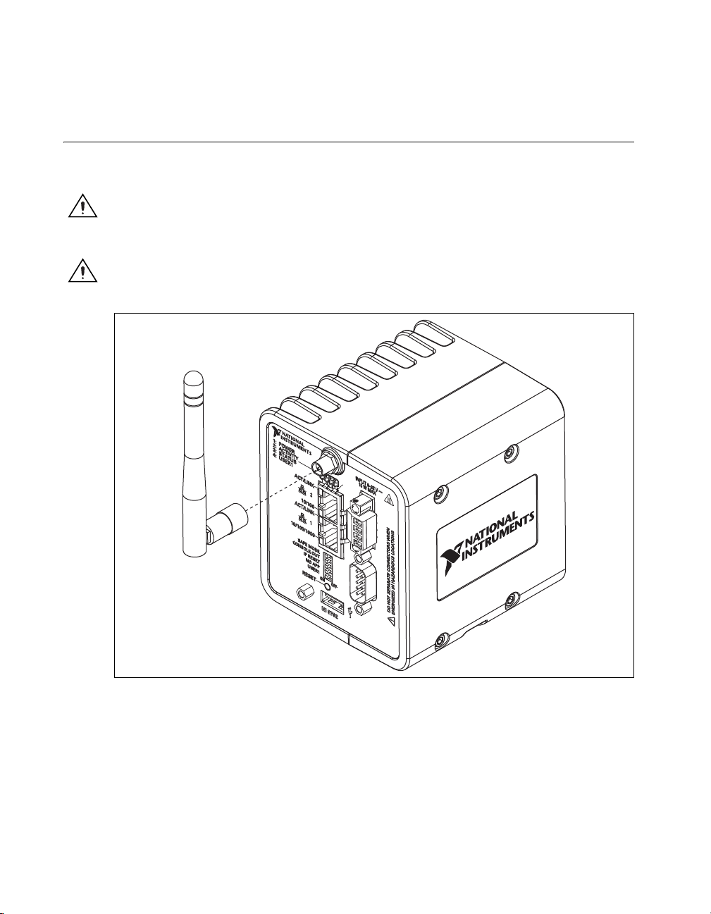
To attach the antenna, align it with the mount, as shown in Figure 4, and screw it on.
Caution The antenna must be attached to the NI WSN device in order for the NI WSN device to
function correctly.
Figure 4. Attach Antenna to Device
NI 9792 WSN Real-Time Gateway User Guide and Specifications 7 ni.com
Page 9
Mounting the NI 9792 Device
You can mount the NI 9792 device on a panel, a 35 mm DIN rail, in an enclosure, or on a desktop. Use
the DIN-Rail mounting method if you already have a DIN rail configuration or if you need to be able to
quickly remove the device. Use the panel mount method for high shock and vibration applications. Use
an enclosure for harsh, dirty, or wet environments. For kit accessory ordering information, refer to the
accessory section of the NI WSN product page at
Caution If the ambient temperature is above 60 °C, you must mount the NI 9792 on a thermally
conductive material. Measure the ambient temperature at each side of the NI 9792, 63.5 mm (2.5 in.)
from the side, and 25.4 mm (1 in.) from the back of the system.
Caution Your installation must meet the following requirements:
• Allows 25.4 mm (1 in.) of clearance above and below the NI 9792 device for air circulation.
• Allows 50.8 mm (2 in.) of clearance in front of the device for common connector cabling, such
as the 4-position detachable screw terminal connector
Note Figure 5 is an actual size template. You can print it out and use it to determine screw hole
placement for panel mounting.
ni.com.
.
NI 9792 WSN Real-Time Gateway User Guide and Specifications 8 ni.com
Page 10
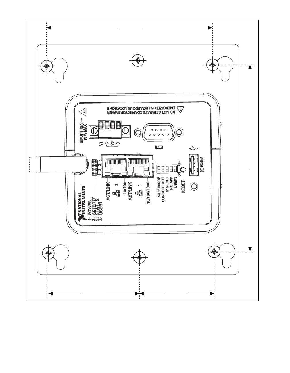
114.3 mm
(4.500 in.)
45.69 mm
(1.799 in.)
55.91 mm
(2.201 in.)
101.6 mm
(4.000 in.)
Figure 5. NI 9792 Panel Mount Dimensions Template
NI 9792 WSN Real-Time Gateway User Guide and Specifications 9 ni.com
Page 11

Attaching to the NI WSN-3282 DIN Rail
Caution Power off the device before mounting it to the DIN rail.
The NI WSN-3282 DIN rail kit, NI part number 781074-01, contains one clip for mounting the device
on a standard 35 mm DIN rail. To mount the device on a DIN rail, complete the following steps:
1. Fasten the DIN rail clip to the device using a number 1 Phillips screwdriver and four 4-40 machine
screws. The screws are included in the DIN rail kit.
2. Make sure the DIN rail kit is installed as shown in Figure 6, with the larger lip of the DIN rail
positioned up.
Note Use 4-40 (finer thread) screw to affix the DIN rail clip to the device.
Figure 6. NI 9792 DIN Rail Installation
Figure 7. DIN Rail Installation Shown without the NI 9792
NI 9792 WSN Real-Time Gateway User Guide and Specifications 10 ni.com
Page 12
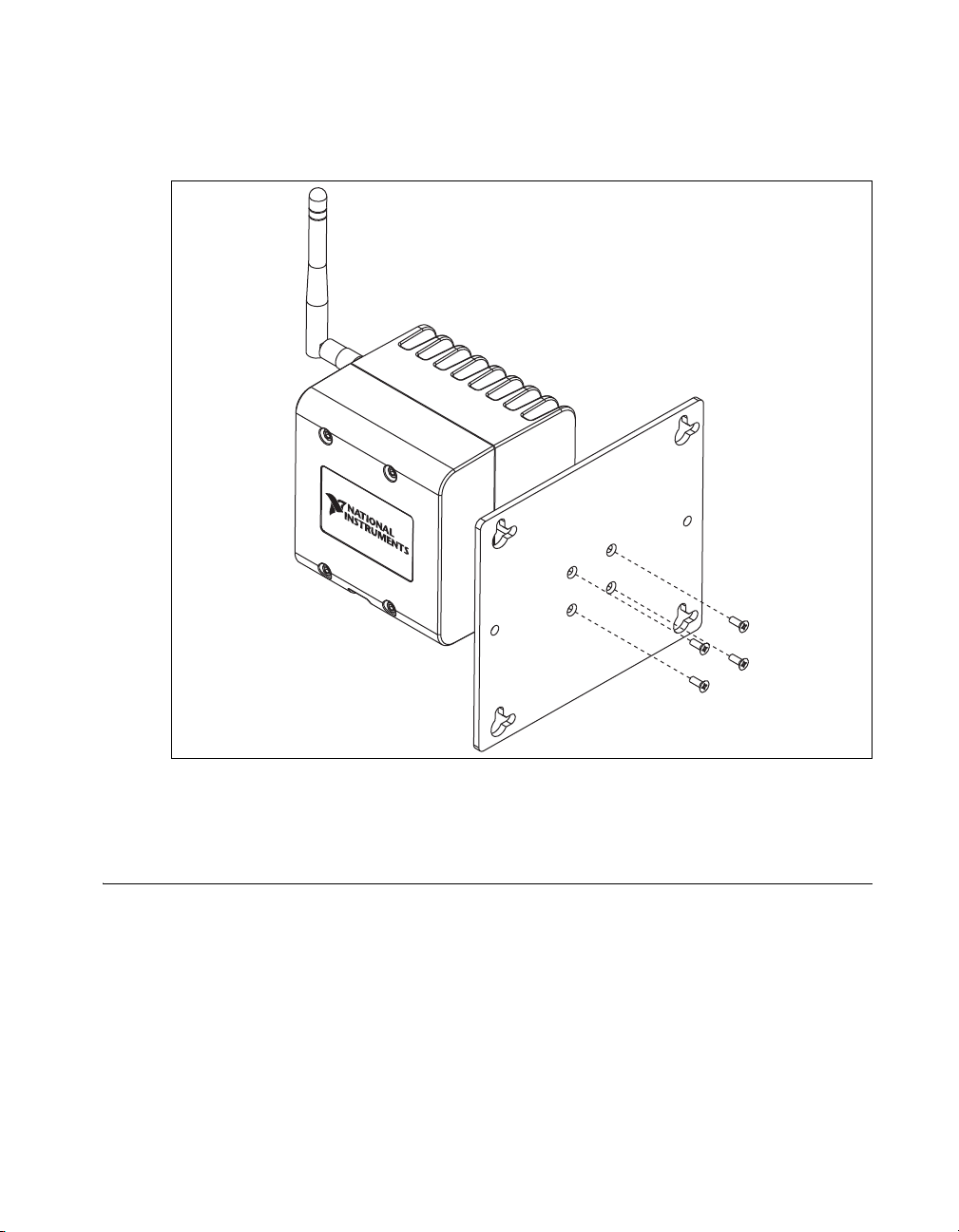
Attaching the NI WSN-3283 Panel Mount Plate
The NI WSN-3283 panel mount kit, NI part number 781075-01, contains a plate for mounting the device
to a panel. To mount the device, complete the following steps:
1. Fasten the plate to the device using a number 1 Phillips screwdriver and 4-40 machine screws, as
shown in Figure 8. The screws are included in the NI WSN-3283 panel mount kit.
Figure 8. Mounting the NI 9792 to the Panel Mount Plate
2. Attach the device and attached plate to a wall or other surface using four to six number 8 or M4
screws. Refer to Figure 5 for the mounting hole template.
Setting Up the NI 9792 Device
Complete the following steps to prepare the NI 9792 device for use:
1. Before connecting the hardware, install NI LabVIEW and the NI-WSN driver software. You must
be an Administrator to install NI software and devices on your computer. The NI-WSN driver
software is on the software installation disc included with your device and is available for download
at
ni.com/support. You must have NI LabVIEW 2009 SP1 (32-bit) or later, NI LabVIEW
Real-Time 2009 SP1 (32-bit) or later, and NI-WSN 1.1 and NI MAX installed to use the NI 9792.
Refer to the instructions included with your NI LabVIEW software to install NI LabVIEW.
Once NI LabVIEW is installed, complete the following steps:
2. Close all other applications.
© National Instruments Corporation 11 NI 9792 WSN Real-Time User Guide and Specifications
Page 13

3. Insert the NI-WSN software installation disc into the drive on your computer.
4. Follow the onscreen instructions to install the NI-WSN software and NI MAX.
Note The NI Wireless Sensor Network Getting Started Guide is available after installation
from Start»All Programs»National Instruments»NI-WSN.
Make sure the NI 9792 device power is disconnected.
5. Attach a ring lug, as shown in Figure 9, to a 14 AWG (1.6 mm) wire. Connect the ring lug to the
ground terminal on the bottom of the device using the ground screw. Attach the other end of the
wire to the system ground.
1
1 Ring Lug Attached to the Ground Screw with Cable Attached
Figure 9. Ring Lug Attached to the Ground Screw
NI 9792 WSN Real-Time Gateway User Guide and Specifications 12 ni.com
Page 14

Connecting the NI 9792 to a Network
Using a standard Category 5 (CAT-5) or better Ethernet cable, connect the NI 9792 to an Ethernet
network using the Ethernet port 1 on the NI 9792.
Caution To prevent data loss and to maintain the integrity of your Ethernet installation, do not use
a cable longer than 100 m. If you are using 100 Mbps Ethernet, National Instruments recommends
using a CAT-5 or better shielded twisted-pair Ethernet cable.
Note You will configure the IP settings and install software on the NI 9792, as described in the
Configuring IP Settings and Installing Software on the NI 9792 section, after connecting power and
powering the NI 9792 on.
The host computer communicates with the NI 9792 over a standard Ethernet connection. If the host
computer is on a network, you must configure the NI 9792 on the same subnet as the host computer. If
neither the host computer nor the NI 9792 is connected to a network, you can connect the two directly.
If you want to use the NI 9792 on a subnet other than the one the host computer is on, first connect the
NI 9792 on the same subnet as the host computer. Use DHCP to assign an IP address or reassign a static
IP address for the subnet where you want it to be and physically move it to the other subnet. The first
time you configure the NI 9792, you must also install software on it. Contact your network administrator
if you need assistance configuring the host computer and NI 9792 on the same subnet.
Note You must connect Ethernet port 1 to configure the NI 9792. You cannot configure the NI 9792
through Ethernet port 2.
In order to use Ethernet port 2, you must assign a static IP address to the port using MAX. The IP address
must be on a different subnet than the IP address of Ethernet port 1. You cannot use DHCP with Ethernet
port 2. For more information about using Ethernet port 2, go to
dualenet.
ni.com/info and enter the info code
Wiring Power to the NI 9792
Caution You must use a UL Listed ITE power supply marked LPS with the NI 9792. The power
supply must also meet any safety and compliance requirements for the country of use.
Caution You must install the NI 9792 and tighten the captive screws before you apply power to the
NI 9792. Installing the NI 9792 while power is applied to it can cause damage to the device.
1. Install the ferrite shipped with the NI 9792 across the negative and positive leads of the power
supply, approximately 50–75 mm (2–3 in.) from the ends of the leads near the NI 9792, as shown
in Figure 10.
Figure 10. Wiring Power to the NI 9792
© National Instruments Corporation 13 NI 9792 WSN Real-Time User Guide and Specifications
Page 15

2. Connect the positive lead of the power supply to the V1 or V2 terminal and the negative lead to one
of the C terminals.
3. Optionally, you can connect the positive lead of another power supply to the other V terminal and
the negative lead to one of the C terminals. You must install the ferrite across both pairs of wires.
Note If you connect power to both V1 and V2, you must ensure that the voltage difference between
the two power inputs, measured at the NI 9792 power connector, is at least 500 mV.
Note The NI 9792 draws power from either V1 or V2, depending on which terminal has a higher
voltage. It does not draw power from both terminals. The NI 9792 switches between V1 and V2
without affecting operation.
Caution The C terminals are internally connected to each other. If you use two power supplies, make
sure they share a common ground.
Caution The C terminals are internally connected to the NI WSN 9792 chassis to prevent a faulty
ground connection from causing the chassis ground to float. If you reverse the input voltage, the
positive input voltage is connected directly to the chassis. The NI 9792 has built-in reversed-voltage
protection, but reversed voltage can damage connected peripherals if the chassis ground is not
reliably connected to earth ground.
Caution Do not tighten or loosen the terminal screws on the power connector while the power
connector is plugged into the NI 9792 or while the power supply is on.
Powering On the NI 9792
Turn on each power supply to the NI 9792 system. The NI 9792 runs a power-on self test (POST).
During the POST, the POWER and STATUS LEDs turn on. When the STATUS LED turns off, the POST
is complete. If the LEDs do not behave in this way when the NI 9792 powers on, refer to the Device
Interface section.
Configuring IP Settings and Installing Software on the NI 9792
When you power on the NI 9792 for the first time, it boots into safe mode because there is no software
installed on it. This section describes how to configure the IP settings and install software on the
NI 9792.
Complete the following steps:
1. Launch MAX on the host computer and expand Remote Systems in the MAX configuration tree.
MAX lists the NI 9792 as the model name of the NI 9792 followed by the serial number, for
example, NI-NI9792-0146793C.
Tip If you cannot find the NI 9792 under Remote Systems, refer to the CONSOLE OUT Switch
section for information about using a serial connection and a terminal program for troubleshooting.
The NI 9792 automatically attempts to connect to the network using DHCP. If DHCP is not
available, the NI 9792 connects to the network with a link-local IP address with the form
x.x
169.254.
2. Select the NI 9792 under Remote Systems to see the Network Settings tab in the middle pane of
MAX.
3. Enter a name for the RT target in the Name field.
4. (Optional) Enter a valid SNTP time server for the RT target in the Additional Configuration
section.
5. Select settings for the RT target in the IP Settings section, and click Apply.
NI 9792 WSN Real-Time Gateway User Guide and Specifications 14 ni.com
.
Page 16

Note For information about configuring network settings, refer to the Configuring Network Settings
book of the MAX Remote Systems Help. In MAX, click Help»Help Topics»Remote Systems. On
the Contents tab, browse to LabVIEW Real-Time Target Configuration»Configuring Network
Settings.
6. Click Apply, and then click Yes at the prompt to reboot the NI 9792. You can also reboot the
NI 9792 by right-clicking the name under Remote Systems and selecting Reboot.
7. After rebooting, the NI 9792 appears under Remote Systems with the assigned name. Expand the
NI 9792 and select Software.
8. Click Add/Remove Software in the toolbar to launch the LabVIEW Real-Time Software Wizard.
9. Install LabVIEW Real-Time software and device drivers on the NI 9792.
After software installation, the NI 9792 automatically reboots. You can now program it using LabVIEW
Real-Time. For information about configuring the NI 9792 to launch an embedded stand-alone
application at startup, refer to the LabVIEW Help.
For more information about setting up the NI 9792 as an RT target, refer to the RT Getting Started Guide,
available on the host computer at Start»All Programs»National Instruments» LabVIEW 2009»
LabVIEW Manuals.
Using the Internal Real-Time Clock
The system clock of the NI 9792 is synchronized with the internal high-precision real-time clock at
startup. This synchronization provides timestamp data to the NI 9792. You can also use the internal
real-time clock to correct drift of the system clock. Refer to the Specifications section for the accuracy
specifications of the real-time clock.
© National Instruments Corporation 15 NI 9792 WSN Real-Time User Guide and Specifications
Page 17

Device Interface
1
5
4
2
10
3
6
7
8
9
8
Figure 11 shows the NI 9792 device interface.
1 Antenna RP-SMA Connector
2 9–35 VDC Power Connector
3 RS-232 Port
4USB Port
5 RESET Button
6 DIP Switches
7 RJ45 Ethernet Port 1, 10/100 LED
8 ACT/LINK LED
9 RJ45 Ethernet Port 2, 10/100 LED
10 LEDs: POWER, ACTIVITY, STATUS, USER1
Figure 11. NI 9792 Device Interface
Connecting Serial Devices to the NI 9792
The NI 9792 has an RS-232 serial port to which you can connect devices such as displays or input
devices. Use the Serial VIs to read from and write to the serial port. For more information about the
Serial VIs, refer to the LabVIEW Help.
Pin 5
Pin 1
Figure 12. NI 9792 RS-232 Serial Port
NI 9792 WSN Real-Time Gateway User Guide and Specifications 16 ni.com
Pin 9
Pin 6
Page 18

Table 1. DB-9 Pin Descriptions
Pin Signal
1 DCD
2 RXD
3 TXD
4 DTR
5 GND
6 DSR
7 RTS
8 CTS
9 RI
Connecting USB Mass Storage Devices to the NI 9792
The NI 9792 supports common USB mass storage devices such as USB Flash drives and USB-to-IDE
adapters formatted with FAT16 and FAT32 file systems. LabVIEW usually maps USB devices to the
U:, V:, W:, or X: drive, starting with the U: drive if it is available. You can connect multiple USB mass
storage devices to the NI 9792 if you use a USB hub. Refer to the LabVIEW Help for more information.
Note If the NI 9792 is not in a hazardous location, you can connect and disconnect USB devices
without affecting operation.
Configuring DIP Switches
SAFE MODE
CONSOLE OUT
IP RESET
NO APP
USER1
OFFON
Figure 13. NI 9792 DIP Switches
All of the DIP switches are in the OFF position when the NI 9792 is shipped from National Instruments.
SAFE MODE Switch
The position of the SAFE MODE switch determines whether the embedded LabVIEW Real-Time
engine launches when the NI 9792 boots. If the switch is in the OFF position, the LabVIEW Real-Time
engine launches. Keep this switch in the OFF position during normal operation. If the switch is in the
ON position when the NI 9792 boots, the NI 9792 launches only the essential services required for
updating its configuration and installing software. In the latter case, the LabVIEW Real-Time engine
does not launch.
© National Instruments Corporation 17 NI 9792 WSN Real-Time User Guide and Specifications
Page 19

Move the SAFE MODE switch to the ON position if the software on the NI 9792 is corrupted. Even if
the switch is not in the ON position, if there is no software installed on the NI 9792, the NI 9792
automatically boots into safe mode. The SAFE MODE switch must be in the ON position to reformat
the drive on the NI 9792. Refer to the Measurement & Automation Explorer Help for more information
about installing software on the NI 9792 and reformatting the drive on the NI 9792.
CONSOLE OUT Switch
With a serial-port terminal program, you can use the CONSOLE OUT switch to read the IP address and
firmware version of the NI 9792. Use a null-modem cable to connect the serial port on the NI 9792 to a
computer. Move the switch to the ON position. Make sure that the serial-port terminal program is
configured to the following settings:
• 9,600 bits per second
• Eight data bits
• No parity
• One stop bit
• No flow control
The serial-port terminal program displays the IP address and firmware version of the NI 9792, and alerts
you when you connect an unsupported USB device to the NI 9792. Keep this switch in the OFF position
during normal operation.
IP RESET Switch
Move the IP RESET switch to the ON position and reboot the NI 9792 to reset the IP address and other
TCP/IP settings of the NI 9792 to the factory defaults. Refer to the Resetting the Network Configuration
section for more information about resetting the IP address.
NO APP Switch
Move the NO APP switch to the ON position to prevent a LabVIEW startup application from running
on the NI 9792 when the NI 9792 powers on. If you want to permanently disable the application from
running when the NI 9792 powers on, you must disable it in LabVIEW. To run an application when the
NI 9792 powers on, move the NO APP switch to the OFF position, create an application using the
LabVIEW Application Builder, and configure the application in LabVIEW to launch when the NI 9792
powers on. If you already have an application configured to launch when the NI 9792 powers on and
you move the NO APP switch from ON to OFF, the startup application is automatically enabled. For
more information about automatically launching VIs when the NI 9792 powers on and disabling VIs
from launching when the NI 9792 powers on, refer to the LabVIEW Help.
USER1 Switch
You can define the USER1 switch for your application. To define the purpose of this switch in your
embedded application, use the RT Read Switch VI in your LabVIEW RT embedded VI. For more
information about the RT Read Switch VI, refer to the LabVIEW Help.
Reset Button
The NI 9792 is equipped with a RESET button as shown in Figure 11. Pressing the RESET button resets
the NI 9792 in the same manner as cycling power.
NI 9792 WSN Real-Time Gateway User Guide and Specifications 18 ni.com
Page 20

LED Indicators
The LED indicators for the NI 9792 device are listed in Table 2.
Table 2. LED State/Device Status
LED Description Color LED State Device Status
10/100 Green On Connected at 100 Mbps
Off No Ethernet connection or
10 Mbps connection
LINK/ACT Green On Ethernet link
Off No Ethernet connection
Blinking Ethernet activity
POWER Green/Yellow Green Powered from V1
Ye ll ow Powered from V2
Off Power off
© National Instruments Corporation 19 NI 9792 WSN Real-Time User Guide and Specifications
Page 21

Table 2. LED State/Device Status (Continued)
LED Description Color LED State Device Status
STATUS Ye ll o w On Device firmware booting or resetting to
factory default.
Off Normal operation.
1 Blink The gateway is unconfigured. Use
MAX to configure the controller. Refer
to the Measurement & Automation
Explorer Help for information about
configuring the gateway.
2 Blinks The gateway has detected an error in its
software. This usually occurs when an
attempt to upgrade the software is
interrupted. Reinstall software on the
gateway. Refer to the Measurement &
Automation Explorer Help for
information about installing software on
the gateway.
3 Blinks The gateway is in safe mode because the
Safe Mode DIP switch is in the ON
position. Refer to the Configuring DIP
Switches section for information about
the Safe Mode DIP switch.
4 Blinks The gateway software has crashed twice
without rebooting or cycling power
between crashes. This usually occurs
when the gateway runs out of memory.
Review your RT VI and check the
gateway memory usage.
Modify the VI as necessary to solve the
memory usage issue.
Continuously
flashing or solid
Error. Reboot device. If problem
persists, reset device to factory default
settings. Contact ni.com/
support
for additional troubleshooting
steps.
NI 9792 WSN Real-Time Gateway User Guide and Specifications 20 ni.com
Page 22

Table 2. LED State/Device Status (Continued)
LED Description Color LED State Device Status
ACTIVITY Green On Radio is active and sending or receiving
data.
Off No radio activity.
USER1 Green/
yellow
You can define the USER1 LED to meet
the needs of your application. To define
the LED, use the RT LEDs VI in
LabVIEW. For more information about
the RT LEDs VI, refer to the LabVIEW
Help.
Resetting the Network Configuration
If the NI 9792 cannot communicate with the network, you can use the IP RESET switch to manually
restore the NI 9792 to the default network settings. When you reboot the NI 9792 with the IP RESET
switch in the ON position, the NI 9792 attempts to connect to the network using DHCP. If the NI 9792
is unable to initiate a DHCP connection, it connects to the network with a link-local IP address with the
form 169.254.x.x.
Complete the following steps to restore the NI 9792 to the default network settings:
1. Move the IP RESET switch to the ON position.
2. Move the RESET button to cycle power to the NI 9792. The STATUS LED flashes once, indicating
that the NI 9792 IP address is unconfigured.
3. Move the IP RESET switch to the OFF position.
You can reconfigure the settings in MAX from a computer on the same subnet. Refer to the
Measurement & Automation Explorer Help for more information about configuring the NI 9792
settings.
Note If the NI 9792 is restored to the factory network settings, the LabVIEW run-time engine does
not load. You must reconfigure the network settings and restart the NI 9792 for the LabVIEW
run-time engine to load.
Adding, Removing, and Replacing NI WSN-32xx Devices
Use NI MAX to add and remove nodes to and from your NI Wireless Sensor Network. You can remove
and insert NI WSN-32xx devices while the system is operating and without powering down the
NI WSN system. NI WSN-32xx devices already working in the system remain operational and
accessible on the network. Commands sent to a missing NI WSN-32xx device return an error response,
but the NI 9792 stores the commands and applies the effects of the commands if a suitable replacement
is installed.
When you remove a NI WSN-32xx device and add a new one, the NI 9792 first verifies that the
replacement device is compatible with the one that was removed. If it is compatible, the NI 9792 device
configures the replacement NI WSN-32xx device with the previous device settings.
For more information, refer to Start»All Programs»National Instruments»NI-WSN»Configuring
WSN in MAX.
© National Instruments Corporation 21 NI 9792 WSN Real-Time User Guide and Specifications
Page 23

NI Wireless Sensor Networks
The NI WSN system is built on an IEEE 802.15.4 wireless mesh network. The 802.15.4 radio in each
NI WSN device provides for low-power communication of measurement data across a large network of
devices. The NI-WSN software builds on top of that to provide network configuration and reliable
communication from the host PC or PAC to the NI WSN-32xx node devices.
Mesh Networking
The NI WSN system consists of two types of devices: gateways and nodes. Gateways act as the network
coordinator, in charge of node authentication, message buffering, and bridging from the 802.15.4
wireless network to the wired Ethernet network. Nodes primarily function as end nodes in the network
to collect data and control DIO channels, but can also be programmed as routers to relay data from other
nodes back to the gateway and Host PC or PAC. Use NI MAX to configure nodes as end nodes or routers.
Figure 1 shows a typical NI Wireless Sensor Network.
The gateways and nodes work together to form a mesh network. The gateway maintains a list of nodes
(by serial number) that have been authorized for network access. When a node powers up, it scans for
available networks, locates either a gateway or router, and attempts to join it. If the gateway has the node
in its list, the node joins the network, downloads the latest configuration from the gateway, and begins
its normal operation of acquiring measurement data and controlling DIO.
Since each node joins a network instead of a particular router or gateway, it can find a new path back
to the gateway in the event that the signal is lost or blocked to its existing network route. In this way,
the mesh network is inherently self-forming and self-healing. However, this may also cause network
throughput to decrease, as there is no way to force a router or end node to join to a particular device in
the network. Each time a node joins through a router, the overall throughput of that node is halved, due
to the fact that the node must hop to get its messages back to the gateway. Figure 14 shows an example
of one possible mesh configuration.
NI 9792 WSN Real-Time Gateway User Guide and Specifications 22 ni.com
Page 24

R
1
G
R
2
Figure 14. Mesh Configuration Example
In this configuration, R1 (a router) and R2 (a router) both communicate directly with the gateway.
Measurements taken by both devices can directly reach the gateway without having to hop through
another node. However, the configuration above does not always mesh in the same way. Figure 15 shows
another possible configuration for the same network.
© National Instruments Corporation 23 NI 9792 WSN Real-Time User Guide and Specifications
Page 25

R
1
G
R
2
Figure 15. Same Network Configuration Example
In this configuration, R1 can still communicate with the gateway, but R2 is now connected through R1.
This means that all measurements taken by R2 must hop through R1 before making it back to the
gateway. In addition, R
is now not only responsible for sending its own measurement data, but also
1
the R2 data. This configuration is considered a worst case 1-hop system, as R2 and R1 both have the
possibility of meshing through a router that is connected to the gateway. National Instruments
recommends configuring your system for no more than three hops. Configuring multiple nodes as
routers and placing them within close proximity introduces the possibility that your system could mesh
inefficiently. Figure 16 shows how a system could mesh efficiently, yet also have the possibility of
meshing inefficiently.
NI 9792 WSN Real-Time Gateway User Guide and Specifications 24 ni.com
Page 26

Figure 16. Inefficient Versus Efficient Meshing
G
G
R
1
R
2
R
3
R
4
R
5
R
6
R
1
R
2
R
3
R
4
R
5
R
6
The network can be improved with two separate techniques:
1. Convert some routers to end nodes.
2. Set up the network to prevent the routers from being in range of each other (spatially separated by
distance, or introducing objects that increase radio interference, such as buildings).
Another advantage of the mesh network is the ability to extend the distance of the end measurement
from the wired Ethernet gateway. By placing mesh routers throughout the space where you wish to
acquire signals, you can expand the area and distance across which measurement data can be acquired
and sent. Refer to the Specifications section for typical line of sight ranges for the NI WSN devices.
Figure 17 shows how a network can be set up to cover greater distances.
R
3
© National Instruments Corporation 25 NI 9792 WSN Real-Time User Guide and Specifications
R
2
Figure 17. Network Containing Distance Example
R
1
G
Page 27

End Node Versus Router
Each NI WSN-32xx node can be configured as either an end node or a router. NI WSN-32xx nodes are
configured by default at the factory in end node mode. You can change the mode of the node using the
NI-WSN software and NI MAX. One trade-off to consider when configuring nodes is power
consumption. NI WSN-32xx nodes configured as end node are designed to be run from battery power
while routers are designed to use external power at all times to send, receive, and buffer messages to and
from end nodes.
Data Transfer in the NI WSN Network
The NI WSN system is built on a low-power, reliable IEEE 802.15.4 network. In order to save power
and increase reliability, this network delivers a maximum theoretical throughput of 250 kbps. This
correlates to a typical maximum rate of 1 sample per second per node.
Measurements taken with NI WSN-32xx nodes are single point acquisition. NI WSN-32xx devices have
no onboard buffer, therefore the data is considered to be lost, meaning there is no way to retrieve past
data from the device.
Configuring Your NI WSN System
As discussed in the Mesh Networking section, creating a reliable and efficient wireless sensor network
requires an understanding of the physical environment of the network, as well as an understanding of
the expected meshing configuration. For example, parent devices (routers and gateways) can only have
a maximum of eight end nodes connected to them at a given time.
This maximum number introduces the stranded node problem. The stranded node problem exists when
a node, configured as an end node, ends up not being able to join a network. Figure 18 shows a network
consisting of one gateway, two routers, and nine end nodes.
NI 9792 WSN Real-Time Gateway User Guide and Specifications 26 ni.com
Page 28

Figure 18. Network Containing Distance, Example 1
G
R
2
R
1
N
N
x 1
x 8
In this case, all nodes have properly meshed, and all nodes can communicate with the gateway. However,
this network could potentially strand end nodes. Figure 19 shows another possible mesh of the same
network.
© National Instruments Corporation 27 NI 9792 WSN Real-Time User Guide and Specifications
Page 29

Figure 19. Network Containing Distance, Example 2
G
R
2
R
1
N
N
x 1
x 8
In this mesh configuration, eight end nodes in range of both R1 and R2 join with R1. This leaves one end
node stranded from the network. This can be corrected in the following two ways:
1. Move the set of eight end nodes to where they can only communicate with R2. This prevents them
from possibly joining R
.
1
2. Add an additional router that is in range of the single end node. This introduces the possibility of
creating additional hops in the network, but also guarantees coverage of all end nodes.
Specifications
Wireless Characteristics
NI 9792 WSN Real-Time Gateway User Guide and Specifications 28 ni.com
These specifications are typical at 25 °C unless otherwise noted. For the NI WSN-32xx specifications,
refer to the device user guides.
Radio mode ............................................................IEEE 802.15.4
RF data rate............................................................250 kbits/s
Frequency band1....................................................ISM 2.4 GHz (2400 MHz to 2483.5 MHz)
Channels
2
...............................................................11–24
Page 30

TX power
Americas +17 dBm max (50 mW) Up to 300 m
Europe/Asia +10 dBm max (10 mW) Up to 150 m
Modulation type.............................................DSSS (O-QPSK)
Receiver sensitivity........................................–102 dBm
Antenna
Connector.......................................................Female RP-SMA connector
VSWR............................................................MAX 2.0
Impedance......................................................50 Ω
Directivity ......................................................Omni
Nominal gain.......................................................... 1.5 dBi
Network Interface
Ethernet port 1 .......................................................10BaseT and 100BaseTX Ethernet
Ethernet port 2 .......................................................10BaseT and 100BaseTX Ethernet
Compatibility .........................................................IEEE 802.3
Communication rates
Ethernet port 1 ...............................................10 Mbps, 100 Mbps, auto-negotiated
Ethernet port 2 ...............................................10 Mbps, 100 Mbps, auto-negotiated
Maximum cabling distance....................................100 m/segment
Ve rs i on Maximum Radio Output Outdoor Range
RS-232 DTE Serial Port
Baud rate ................................................................300–230, 400 bps
Data bits .................................................................5, 6, 7, 8
Stop bits .................................................................1, 1.5, 2
Parity......................................................................Odd, even, mark, space, none
Flow control...........................................................RTS/CTS, XON/XOFF, DTR/DSR, none
USB Port
Maximum data rate ................................................480 Mb/s
Maximum current ..................................................500 mA
1
Due to regulations, the frequency bands depend upon the country of operation.
2
Due to regulations, the valid channels depend upon country of operation.
© National Instruments Corporation 29 NI 9792 WSN Real-Time User Guide and Specifications
Page 31

Memory
Non-volatile ...........................................................2 GB
Use the following formula to determine the minimum life span in years of the nonvolatile memory:
Memory life span in years = Amount of memory in NI 9792 (MB)
100,000/365 days]/[file size (MB)
DRAM ...................................................................256 MB
Internal Real-Time Clock
Accuracy ................................................................200 ppm; 35 ppm at 25 °C
Integrated Voltage Input Monitor
The integrated voltage input monitor under reports the voltage at the power connector by up to 400 mV
because of voltage drops across internal circuits.
Power Requirements
Caution You must use a UL Listed ITE power supply marked LPS with the NI 9792. The power
supply must also meet any safety and compliance requirements for the country of use.
Recommended power supply.................................15 W secondary, 35 VDC max
Power consumption................................................9.5 W
Maximum power consumption ..............................15 W
Voltage requirement
On powerup....................................................9 to 35 V
After powerup ................................................6 to 35 V
Note For EMC compliance, operate this device with shielded cables. The NI 9792 is guaranteed to
power up when 9 V is applied to V and C. After power up, it can operate on as little as 6 V.
×
× write rate (per day)]
Physical Characteristics
If you need to clean the NI 9792, wipe it with a dry towel.
Screw-terminal wiring ...........................................12–18 AWG shielded copper conductor wire with 10
mm (0.39 in.) of insulation stripped from the end
Torque for screw terminals .................................... 0.5 to 0.6 N · m
(4.4 to 5.3 lb · in.)
Weight ....................................................................Approx. 833 g (29.4 oz)
Weight with antenna .............................................Approx. 842 g (29.7 oz)
Dimensions ............................................................Refer to Figure 3 for device dimensions.
Safety Standards
Note For UL and other safety certifications, refer to the product label, or go to ni.com/
certification
Certification column.
NI 9792 WSN Real-Time Gateway User Guide and Specifications 30 ni.com
, search by model number or product line, and click the appropriate link in the
Page 32

The NI 9792 is designed to meet the requirements of the following standards of safety for electrical
equipment for measurement, control, and laboratory use:
• IEC 61010-1, EN 61010-1
• UL 61010-1, CSA 61010-1
Hazardous Locations
U.S. (UL) ...............................................................Class I, Division 2, Groups A, B, C, D, T4;
Class I, Zone 2, AEx nC IIC T4
Canada (C-UL) ......................................................Class I, Division 2, Groups A, B, C, D, T4;
Class I, Zone 2, Ex nA IIC T4
Europe (DEMKO)..................................................Ex nA nL IIC T4
Note For UL and other safety certifications, refer to the product label, or go to ni.com/
certification
Certification column.
, search by model number or product line, and click the appropriate link in the
Safety Voltages
Connect only voltages that are within these limits.
V terminal to C terminal ........................................ 35 V max, Measurement Category I
Measurement Category I is for measurements performed on circuits not directly connected to the
electrical distribution system referred to as MAINS voltage. MAINS is a hazardous live electrical supply
system that powers equipment. This category is for measurements of voltages from specially protected
secondary circuits. Such voltage measurements include signal levels, special equipment, limited-energy
parts of equipment, circuits powered by regulated low-voltage sources, and electronics.
Caution Do not connect the system to signals or use for measurements within Measurement
Categories II, III, or IV.
RF Safety Warning
This product complies with FCC radiation exposure limits set for uncontrolled equipment and meets the
FCC radio frequency (RF) Exposure Guidelines in Supplement C to OET65. This product generates and
radiates radio frequency energy. To comply with the radio frequency radiation exposure guidelines in an
uncontrolled environment, this equipment should be installed and operated with at least 20 cm between
the radiator and the person’s body (excluding extremities: hands, wrists, feet, and legs).
This product complies with the European Council Recommendation (1995/519/EC) on the limitation of
exposure of the general public to electromagnetic fields. Compliance was determined in accordance
with the requirements in EN 50371.
Electromagnetic Compatibility
This product is designed to meet the requirements of the following standards of EMC for electrical
equipment for measurement, control, and laboratory use:
• EN 61326-1 (IEC 61326-1): Class A emissions; Basic Immunity
• EN 55011 (CISPR 11): Group 1, Class A emissions
• AS/NZS CISPR 11, Group 1, Class A emissions
• FCC 47 CFR Part 15B: Class A emissions
• ICES-001: Class A emissions
© National Instruments Corporation 31 NI 9792 WSN Real-Time User Guide and Specifications
Page 33

The NI 9792 also meets the requirements of the following EMC standards for intentional radiators:
• EN 300 328
• EN 301 489-1 and EN 301 489-17
• FCC 47 CFR Part 15C
• IC RSS-210
Note For the standards applied to access the EMC of this product, refer to the Online Product
Certification section.
CE Compliance
This product meets the essential requirements of applicable European Directives as follows:
• 2006/95/EC; Low-Voltage Directive (safety)
• 2004/108/EC; Electromagnetic Compatibility Directive (EMC)
• 1999/5/EC; Radio and Telecommunications Terminal Equipment (R&TTE) Directive
Regulatory Information
United States
This product complies with Part 15 of the FCC Rules. Operation is subject to these two conditions:
(1) this device may not cause harmful interference, and (2) this device must accept any interference
received, including interference that may cause undesired operation.
Canada
This product complies with Industry Canada RSS-210.
Cet appareil est conforme aux norme RSS210 d’Industrie Canada.
Europe—EU Declaration of Conformity
Marking by the above CE symbol on the label indicates compliance with the Essential Requirements of
the R&TTE Directive of the European Union (1999/5/EC). This equipment meets the following
conformance standards: EN 301489-01, EN300 328, EN301 489-17, EN60950.
Europe – Restrictions for Use of 2.4 GHz Frequencies in European Community Countries
België/
Belgique:
Deutschland: License required for outdoor installations. Check with reseller for procedure to follow.
For private usage outside buildings across public grounds over less than 300 m no special registration
with IBPT/BIPT is required. Registration to IBPT/BIPT is required for private usage outside buildings
across public grounds over more than 300 m. For registration and license please contact IBPT/BIPT.
Voor privé-gebruik buiten gebouw over publieke groud over afstand kleiner dan 300 m geen registratie
bij BIPT/IBPT nodig; voor gebruik over afstand groter dan 300 m is wel registratie bij BIPT/IBPT
nodig. Voor registratie of licentie kunt u contact opnemen met BIPT.
Dans le cas d’une utilisation privée, à l’extérieur d’un bâtiment, au-dessus d’un espace public, aucun
enregistrement n’est nécessaire pour une distance de moins de 300 m. Pour une distance supérieure à
300 m un enregistrement auprès de I’IBPT est requise. Pour les enregistrements et licences, veuillez
contacter I’IBPT.
Anmeldung im Outdoor-Bereich notwendig, aber nicht genehmigungspflichtig.Bitte mit Händler die
Vorgehensweise abstimmen.
NI 9792 WSN Real-Time Gateway User Guide and Specifications 32 ni.com
Page 34

France: Restricted frequency band: only channels 1 to 7 (2400 MHz and 2454 MHz respectively) may be used
outdoors in France.
Bande de fréquence restreinte : seuls les canaux 1–7 (2400 et 2454 MHz respectivement) doivent être
utilisés endroits extérieur en France. Vous pouvez contacter I’Autorité de Régulation des
Télécommuniations (
Italia: License required for indoor use. Use with outdoor installations not allowed.
E'necessaria la concessione ministeriale anche per l’uso interno.
Verificare con i rivenditori la procedura da seguire.
Nederland: License required for outdoor installations. Check with reseller for procedure to follow.
Licentie verplicht voor gebruik met buitenantennes. Neem contact op met verkoper voor juiste
procedure.
http://www.art-telecom.fr) pour la procédure à suivre.
Japan
The certified radio equipment is embedded in this device.
本機器には認証済み無線設備が内蔵されています
Singapore
Complies with
IDA Standards
DA105692
Taiwan R.O.C.
低功率電波輻射性電機管理辦法
第十二條經型式認證合格之低功率射頻電機,非經許可,公司、商號或使
用者均不得擅自變更頻率、加大功率或變更原設計之特性及功能。
第十四條低功率射頻電機之使用不得影響飛航安全及幹擾合法通信;經發
現有幹擾現象時,應立即停用,並改善至無幹擾時方得繼續使用。
前項合法通信,指依電信規定作業之無線電信。低功率射頻電機須忍受合法通信
或工業、科學及醫療用電波輻射性電機設備之幹擾。
EU Regulatory Statements
Česky
[Czech]
Dansk
[Danish]
Deutsch
[German]
© National Instruments Corporation 33 NI 9792 WSN Real-Time User Guide and Specifications
National Instruments tímto prohlašuje, _e tento NI WSN-9792 je ve shodě se základními
po_adavky a dalšími příslušnými ustanoveními směrnice 1999/5/ES.
Undertegnede National Instruments erklćrer herved, at fřlgende udstyr NI WSN-9792
overholder de vćsentlige krav og řvrige relevante krav i direktiv 1999/5/EF.
Hiermit erklärt National Instruments, dass sich das Gerät NI WSN-9792 in
Übereinstimmung mit den grundlegenden Anforderungen und den übrigen einschlägigen
Bestimmungen der Richtlinie 1999/5/EG befindet.
Page 35

Eesti
[Estonian]
Käesolevaga kinnitabNational Instruments seadme NI WSN-9792 vastavust direktiivi
1999/5/EÜ põhinõuetele ja nimetatud direktiivist tulenevatele teistele asjakohastele
sätetele.
English Hereby, National Instruments, declares that this NI WSN-9792 is in compliance with the
essential requirements and other relevant provisions of Directive 1999/5/EC.
Español
[Spanish]
Ελληνική
[Greek]
Por medio de la presente National Instruments declara que el NI WSN-9792 cumple con
los requisitos esenciales y cualesquiera otras disposiciones aplicables o exigibles de la
Directiva 1999/5/CE.
ΜΕ ΤΗΝ ΠΑΡΟΥΣΑ National Instruments ΔΗΛΩΝΕΙ ΟΤΙ NI WSN-9792
ΣΥΜΜΟΡΦΩΝΕΤΑΙ ΠΡΟΣ ΤΙΣ ΟΥΣΙΩΔΕΙΣ ΑΠΑΙΤΗΣΕΙΣ ΚΑΙ ΤΙΣ ΛΟΙΠΕΣ ΣΧΕΤΙΚΕΣ
ΔΙΑΤΑΞΕΙΣ ΤΗΣ ΟΔΗΓΙΑΣ 1999/5/ΕΚ.
Français
[French]
Italiano
[Italian]
Latviski
[Latvian]
Lietuvių
[Lithuanian]
Nederlands
[Dutch]
Malti
[Maltese]
Magyar
[Hungarian]
Polski
[Polish]
Português
[Portuguese]
Slovensko
[Slovenian]
Slovensky
[Slovak]
Suomi
[Finnish]
Svenska
[Swedish]
Par la présente National Instruments déclare que l'appareil NI WSN-9792 est conforme
aux exigences essentielles et aux autres dispositions pertinentes de la directive
1999/5/CE.
Con la presente National Instruments dichiara che questo NI WSN-9792 è conforme ai
requisiti essenziali ed alle altre disposizioni pertinenti stabilite dalla direttiva 1999/5/CE.
Ar šo National Instruments deklarē, ka NI WSN-9792 atbilst Direktīvas 1999/5/EK
būtiskajām prasībām un citiem ar to saistītajiem noteikumiem.
Šiuo National Instruments deklaruoja, kad šis NI WSN-9792 atitinka esminius reikalavimus
ir kitas 1999/5/EB Direktyvos nuostatas.
Hierbij verklaart National Instruments dat het toestel NI WSN-9792 in overeenstemming is
met de essentiële eisen en de andere relevante bepalingen van richtlijn 1999/5/EG.
Hawnhekk, National Instruments, jiddikjara li dan NI WSN-9792 jikkonforma mal-htigijiet
essenzjali u ma provvedimenti ohrajn relevanti li hemm fid-Dirrettiva 1999/5/EC.
Alulírott, National Instruments nyilatkozom, hogy a NI WSN-9792 megfelel a vonatkozó
alapvetõ követelményeknek és az 1999/5/EC irányelv egyéb elõírásainak.
Niniejszym National Instruments. oświadcza, że NI WSN-9792 jest zgodny z zasadniczymi
wymogami oraz pozostałymi stosownymi postanowieniami Dyrektywy 1999/5/EC.
National Instruments declara que este NI WSN-9792 está conforme com os requisitos
essenciais e outras disposições da Directiva 1999/5/CE.
National Instruments izjavlja, da je ta NI WSN-9792 v skladu z bistvenimi zahtevami in
ostalimi relevantnimi določili direktive 1999/5/ES.
National Instruments týmto vyhlasuje, _e NI WSN-9792 spĺňa základné po_iadavky a
všetky príslušné ustanovenia Smernice 1999/5/ES.
National Instruments vakuuttaa täten että NI WSN-9792 tyyppinen laite on direktiivin
1999/5/EY oleellisten vaatimusten ja sitä koskevien direktiivin muiden ehtojen mukainen.
Härmed intygar National Instruments att denna NI WSN-9792 står I överensstämmelse
med de väsentliga egenskapskrav och övriga relevanta bestämmelser som framgår av
direktiv 1999/5/EG.
Íslenska
[Icelandic]
Norsk
[Norwegian]
Hér með lýsir National Instruments yfir því að NI WSN-9792 er í samræmi við grunnkröfur
og aðrar kröfur, sem gerðar eru í tilskipun 1999/5/EC.
National Instruments erklærer herved at utstyret NI WSN-9792 er i samsvar med de
grunnleggende krav og øvrige relevante krav i direktiv 1999/5/EF.
NI 9792 WSN Real-Time Gateway User Guide and Specifications 34 ni.com
Page 36

Online Product Certification
Note Refer to the product Declaration of Conformity (DoC) for additional regulatory compliance
information. To obtain product certifications and the DoC for this product, visit
certification
, search by model number or product line, and click the appropriate link in the
Certification column.
Shock and Vibration
To meet these specifications for shock and vibration, you must panel mount or wall mount the WSN
system, affix ferrules to the ends of all terminal wires, install a strain relief on the power cable, and
install tie wraps on the Ethernet and power cables. You can order the NI 9979, a strain-relief kit for the
power cable, from National Instruments. The kit is NI part number 196939-01.
Operating vibration, random
(IEC 60068-2-64)...................................................5 g
Operating shock
(IEC 60068-2-27)...................................................30 g, 11 ms half sine,
Operating vibration, sinusoidal
(IEC 60068-2-6).....................................................5 g, 10 to 500 Hz
Environmental
Operating temperature
(IEC-60068-2-1 and IEC-60068-2-2) ....................–40 to 70 °C
Storage temperature
(IEC-60068-2-1 and IEC-60068-2-2) ....................–40 to 85 °C
Ingress protection................................................... IP 40
Operating humidity (IEC-60068-2-56)..................10 to 90% RH, noncondensing
Storage humidity (IEC-60068-2-56)......................5 to 95% RH, noncondensing
Pollution Degree (IEC 60664) ...............................2
Maximum altitude..................................................2,000 m
Indoor use only
, 10 to 500 Hz
rms
50 g, 3 ms half sine,
18 shocks at 6 orientations
ni.com/
Environmental Management
NI is committed to designing and manufacturing products in an environmentally responsible manner. NI
recognizes that eliminating certain hazardous substances from our products is beneficial to the
environment and to NI customers.
For additional environmental information, refer to the NI and the Environment Web page at
environment
. This page contains the environmental regulations and directives with which
NI complies, as well as other environmental information not included in this document.
Waste Electrical and Electronic Equipment (WEEE)
EU Customers At the end of the product life cycle, all products must be sent to a WEEE recycling
center. For more information about WEEE recycling centers, National Instruments WEEE initiatives,
and compliance with WEEE Directive 2002/96/EC on Waste and Electronic Equipment, visit
ni.com/environment/weee.
© National Instruments Corporation 35 NI 9792 WSN Real-Time User Guide and Specifications
ni.com/
Page 37

Battery Replacement and Disposal
Cd/Hg/Pb
⬉ᄤֵᙃѻક∵ᶧࠊㅵ⧚ࡲ⊩ ˄Ё
RoHS
˅
Ёᅶ᠋
National Instruments
ヺড়Ё⬉ᄤֵᙃѻકЁ䰤ࠊՓ⫼ᶤѯ᳝ᆇ⠽䋼ᣛҸ
(RoHS)
DŽ
݇Ѣ
National Instruments
Ё
RoHS
ড়㾘ᗻֵᙃˈ䇋ⱏᔩ
ni.com/environment/rohs_china
DŽ
(For information about China RoHS compliance, go to
ni.com/environment/rohs_china
.)
Battery Directive This device contains a long-life coin cell battery. If you need to replace it, use the
Return Material Authorization (RMA) process or contact an authorized National Instruments service
representative. For more information about compliance with the EU Battery Directive 2006/66/EC about
Batteries and Accumulators and Waste Batteries and Accumulators, visit
batterydirective
.
ni.com/environment/
NI 9792 WSN Real-Time Gateway User Guide and Specifications 36 ni.com
Page 38

Where to Go for Support
National Instruments corporate headquarters is located at 11500 North Mopac Expressway, Austin,
Texas, 78759-3504. National Instruments also has offices located around the world to help address
your support needs. For telephone support in the United States, create your service request at
ni.com/support and follow the calling instructions or dial 512 795 8248. For telephone support
outside the United States, contact your local branch office:
Australia 1800 300 800, Austria 43 662 457990-0, Belgium 32 (0) 2 757 0020,
Brazil 55 11 3262 3599, Canada 800 433 3488, China 86 21 5050 9800,
Czech Republic 420 224 235 774, Denmark 45 45 76 26 00, Finland 358 (0) 9 725 72511,
France 01 57 66 24 24, Germany 49 89 7413130, India 91 80 41190000, Israel 972 3 6393737,
Italy 39 02 41309277, Japan 0120-527196, Korea 82 02 3451 3400, Lebanon 961 (0) 1 33 28 28,
Malaysia 1800 887710, Mexico 01 800 010 0793, Netherlands 31 (0) 348 433 466,
New Zealand 0800 553 322, Norway 47 (0) 66 90 76 60, Poland 48 22 328 90 10,
Portugal 351 210 311 210, Russia 7 495 783 6851, Singapore 1800 226 5886,
Slovenia 386 3 425 42 00, South Africa 27 0 11 805 8197, Spain 34 91 640 0085,
Sweden 46 (0) 8 587 895 00, Switzerland 41 56 2005151, Taiwan 886 02 2377 2222,
Thailand 662 278 6777, Turkey 90 212 279 3031, United Kingdom 44 (0) 1635 523545
National Instruments, NI, ni.com, and LabVIEW are trademarks of National Instruments Corporation.
Refer to the Terms of Use section on ni.com/legal for more information about National
Instruments trademarks. Other product and company names mentioned herein are trademarks or trad e
names of their respective companies. For patents covering National Instruments products/technology,
refer to the appropriate location: Help»Patents in your software, the patents.txt file on your
media, or the National Instruments Patent Notice at ni.com/patents.
© 2010 National Instruments Corporation. All rights reserved.
372998B-01 Nov10
Page 39

Artisan Technology Group is your source for quality
new and certied-used/pre-owned equipment
• FAST SHIPPING AND
DELIVERY
• TENS OF THOUSANDS OF
IN-STOCK ITEMS
• EQUIPMENT DEMOS
• HUNDREDS OF
MANUFACTURERS
SUPPORTED
• LEASING/MONTHLY
RENTALS
• ITAR CERTIFIED
SECURE ASSET SOLUTIONS
SERVICE CENTER REPAIRS
Experienced engineers and technicians on staff
at our full-service, in-house repair center
Instra
Remotely inspect equipment before purchasing with
our interactive website at www.instraview.com
Contact us: (888) 88-SOURCE | sales@artisantg.com | www.artisantg.com
SM
REMOTE INSPECTION
View
WE BUY USED EQUIPMENT
Sell your excess, underutilized, and idle used equipment
We also offer credit for buy-backs and trade-ins
www.artisantg.com/WeBuyEquipment
LOOKING FOR MORE INFORMATION?
Visit us on the web at www.artisantg.com for more
information on price quotations, drivers, technical
specications, manuals, and documentation
 Loading...