

Page 1
USER MANUAL
NI 9755
NI Powertrain Controls CompactRIO NOx Sensor Module Kit
Contents
Introduction .............................................................................................................................. 1
System Diagram ....................................................................................................................... 2
Hardware .................................................................................................................................. 2
Powering the Hardware ............................................................................................................ 3
Wiring Harness ......................................................................................................................... 5
Introduction
The National Instruments 9755 CompactRIO NOx Sensor Module Kit interfaces with NOx and
exhaust gas sensors.
O
2
Features
• Configurable from one to four channels
• Measures NOx (ppm) and O2 (%) concentrations
• Sensor controller supply voltage of 12 V to 16 V (24 V version available)
• Reverse battery protection on sensor controller module
• Sensor controller module harness
• LabVIEW FPGA and RT VIs for quick integration with application
• Integration with existing PXI or CompactRIO chassis hardware
Page 2
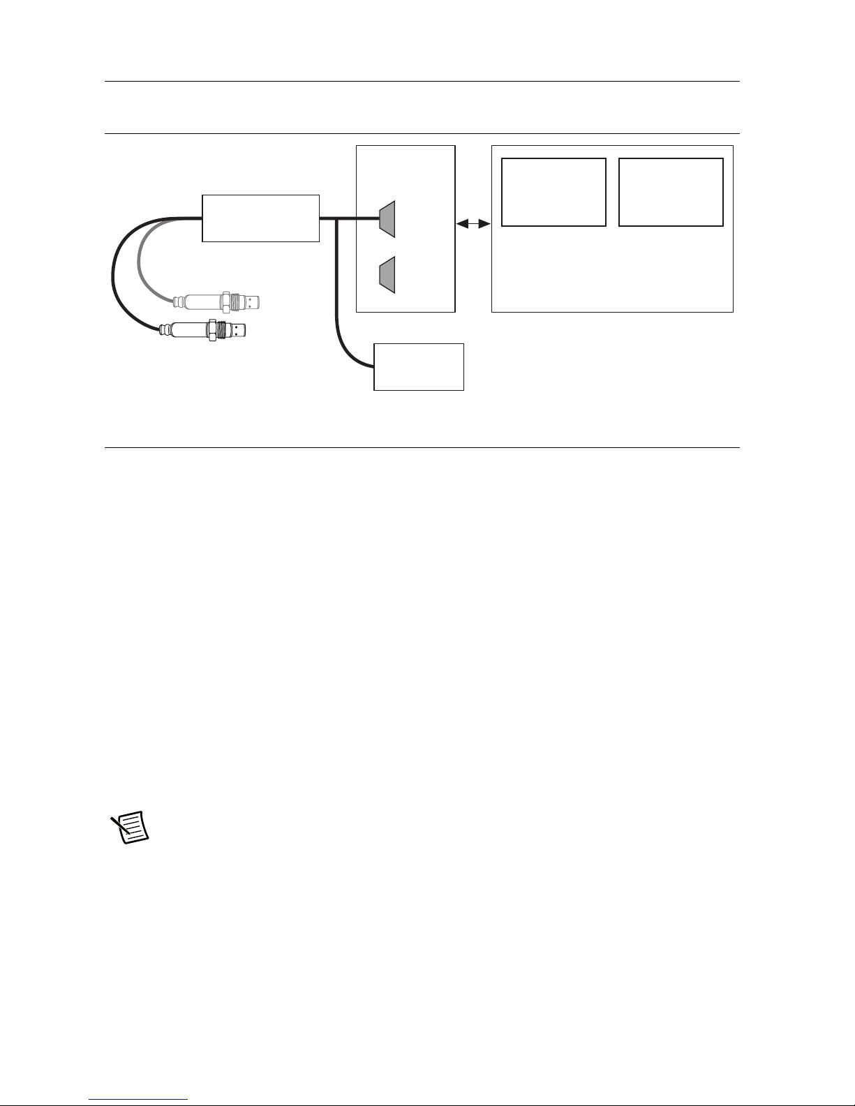
System Diagram
NI USB-9853
CompactRIO
Optional Second Sensor
CAN 1
CAN 2
LabVIEW FPGA
Interface to
NI 9853
LabVIEW RT
Interface to
LabVIEW FPGA
National Instruments Software Support
Provides NOx and O2 Data to
User Application
Sensor
Control Module(s)
DC Power
Supply 12V
Figure 1. NI 9755 System
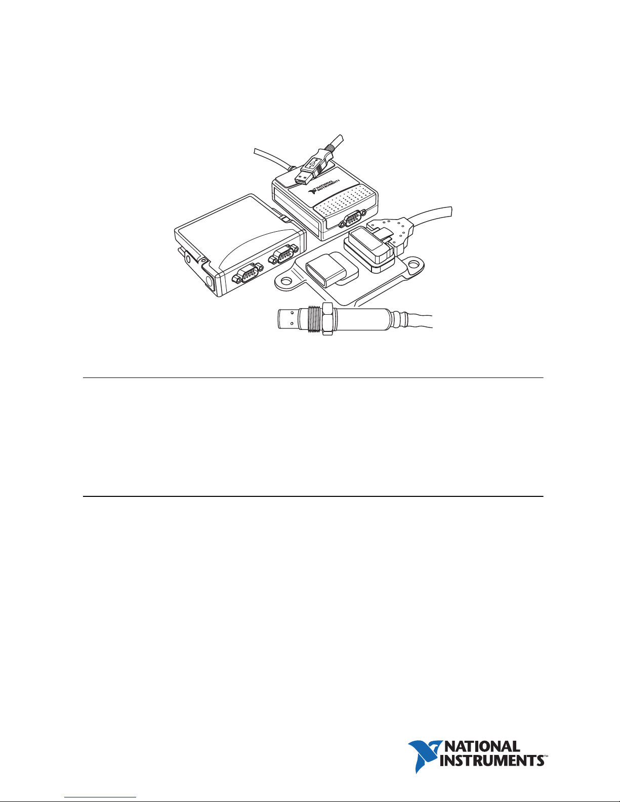
Hardware
The NI 9755 includes the following hardware:
• Continental UniNOx Smart NOx Sensor with integrated sensor controller module
• Sensor bung
• Wiring harness
• NI-9853 CompactRIO High-Speed CAN module
The wiring harness in the NI 9755 connects to the NOx Sensor Control Module and splits into
two cables for the NI-9853 module and an external power supply. The first cable connects to the
NI-9853 with a female DB-9 connector. A terminating resistor of approximately 120 Ω is located
inside this cable near the NOx Sensor Control Module and between the CAN High and CAN
Low wires. The second cable provides three non-terminated leads for connecting to a power
supply, which requires two leads, and for address selection of the NOx Sensor Module, which
requires one lead. If the cable is to be extended, follow CAN network wiring guidelines.
Refer to the NI 9853 CAN Module Operating Instructions and Specifications for more
information on cabling requirements.
Note You must use the sensor included in the NI 9755 kit. NI does not support other
sensors.
2 | ni.com | NI 9755 User Manual
Page 3

Powering the Hardware
The NI 9755 requires power from a range of 12 V to 16 V with a continuous current of 1.5 A
and a peak current of 16 A. The maximum power requirement is 20 W, which typically occurs
when the heating element is being turned on from a cold state. If you are using two sensors,
double the capacity of the power supply.
Refer to the NI 9853 Operating Instructions and Specifications for more information on power
requirements.
Contact National Instruments for more information about sensor specifications.
NOx Sensor Light-Off Times
Conditions
Air T ......................................................... 25 ±5 °C
Batt V........................................................ 14 V
Heater........................................................ ON
................................................................... < 100 s
NO
x
O2...................................................................... < 80 s
NOx Sensor Preheating Function
When power is supplied to the sensor, the sensor enters preheating mode automatically until the
Sensor Enable Boolean is set to TRUE within the supporting software. The Sensor Enable
Boolean turns the internal sensor heater to its ON state. If the Sensor Enable Boolean is set to
FALSE, the sensor returns to preheating mode. The preheating mode protects the sensor from
mechanical cracks caused by water splash.
NOx Sensor Operating Temperature Ranges
Sensor module controller temperature.............. -40 °C to 105 °C
(105 °C to 115 °C for a maximum of 10 minutes)
Storage temperature range ................................ -40 °C to 120 °C
Maximum storage time ..................................... 2 years
Maximum exhaust gas temperature.................. 800 °C (950 °C for a maximum of 100 hours)
Maximum sensor hexagon screw temperature ...620 °C (650 °C for a maximum of 100 hours)
Maximum sensor grommet temperature........... 200 °C (230 °C for a maximum of 100 hours)
Preheating sensor temperature.......................... 80 °C to 120 °C
Lifespan approved by life cycle pattern ........... 2,000 hours or 120 K miles
NI 9755 User Manual | © National Instruments | 3
Page 4

NOx Sensor Electrical Characteristics
NOx Sensor Supply Voltage
Minimum supply voltage ..................................12 V
Maximum supply voltage ................................. 16 V
NOx Sensor Supply Current
Average supply current ..................................... 1.5 A
Peak supply current at switch on ......................16 A
Supply Power
Maximum supply power ................................... 20 W
NOx Sensor Miscellaneous
Thread Torque................................................... 50 N · m (36.88 lb · ft)
Lubrication........................................................ Anti-seize compound
Figure 2. Installation Position
To p
0°
+80°
Exhaust Gas Pipe
Figure 3. Tilt Angle in Gas Flow Direction
90°
–10° +10°
–80°
D/E
4 | ni.com | NI 9755 User Manual
Page 5

NOx Sensor Controller Module Connector
Type of connector .............................................Hirschmann MLK 872-860-501
Number of pins .................................................5
Connector pin assignment
Pin 1 .......................................................... Battery [red]
Pin 2 .......................................................... Ground [black]
Pin 3 .......................................................... CAN Low [blue]
Pin 4 .......................................................... CAN High [orange]
Pin 5 .......................................................... Address Switch [purple]
Pulling Pin 5 to ground changes the CAN transmit ID of the NOx sensor control module so that
two NOx sensor control modules can be added to the same network. Sensor Control Modules
with Pin 5 floating are Ch. 1 and Sensor Control Modules with Pin 5 grounded are Ch. 2.
Wiring Harness
Sensor 1
Sensor 2
Sensor
Control Module
Sensor
Control Module
Figure 4. 2-Sensor Harness
1. Batt
2. Gnd
3. CAN-Low
4. CAN-High
1. Batt
2. Gnd
3. CAN-Low
4. CAN-High
5. Add. Sw
• Each leg from the junction is 4 ft
• Batt, Gnd, and CAN wires are 20 AWG
• 120 Ω resistors across CAN-Low and CAN-High near sensor 1 and 2
• NI-CAN devices connect to the harness through a female DB-9 connector
• CAN-Ground is connected to Ground near junction
• Add. Sw should be connected to ground at the power supply
1
CAN-Low .2
CAN-High .7
CAN-Gnd .6
Batt .9
Batt
Gnd
Add. Sw
1
Power Supply
NI-CAN
Device
12 V DC
1
Batt and GND wires manufactured in 2018 or earlier use 18 AWG wires.
Refer to the NI Trademarks and Logo Guidelines at ni.com/trademarks for more information on National Instruments trademarks. Other
product and company names mentioned herein are trademarks or trade names of their respective companies. For patents covering National
Instruments products/technology, refer to the appropriate location: Help»Patents in your software, the patents.txt file on your media, or
the National Instruments Patents Notice at ni.com/patents. You can find information about end-user license agreements (EULAs) and
third-party legal notices in the readme file for your NI product. Refer to the Export Compliance Information at
ni.com/legal/export-compliance for the National Instruments global trade compliance policy and how to obtain relevant HTS
© 2013–2019 National Instruments. All rights reserved.
376104B-01 Apr19
 Loading...