

Page 1

Getting Started with NI 9514/16 C Series Modules and AKD Servo Drives
This document explains how to install and configure the AKD servo drives for use with the
NI 9514 and NI 9516 C Series drive interface modules.
Tip If you encounter any problems during setup, refer to the Tips and
Troubleshooting section for assistance.
Contents
What You Need to Get Started ................................................................................................. 2
Hardware .......................................................................................................................... 2
Software............................................................................................................................ 3
Hardware Installation and Configuration ................................................................................. 4
Step 1: Set Up the Real Time System............................................................................... 5
Step 2: Connect NI 9514/16 to AKD Drive Cable to the C Series Module ..................... 5
Step 3: Mount the Drive and Connect the Protective Earth ............................................. 7
Step 4: Connect the Logic Power Supply to the NI 9514/16 to AKD Drive Cable ......... 7
Step 5: Connect the NI 9514/16 to AKD Drive Cable to the AKD Servo Drive ............. 7
Step 6: Connect the Motor and Encoder to the Drive....................................................... 9
Step 7: Connect the AC Input Power................................................................................ 9
Step 8: Connect the Drive Communication...................................................................... 11
Step 9: Confirm Drive Connections ................................................................................. 12
Software Installation and Configuration................................................................................... 12
Step 1: Install Software on and Configure the NI RT Controller..................................... 12
Step 2: Creating a Project and Adding NI RT Controller................................................. 13
A. CompactRIO Controller....................................................................................... 13
B. EtherCAT Master and NI 9144 EtherCAT Expansion Chassis ........................... 14
C. NI 9146/7/8/9 Ethernet RIO Expansion Chassis ................................................. 15
Step 3: Adding an NI SoftMotion Axis to the Project...................................................... 15
Step 4: Configure the NI 9514 or NI 9516 C Series Modules.......................................... 17
Step 5: Install AKD WorkBench and Configure the Drive.............................................. 20
Step 6: Enable and Test the Drive using LabVIEW ......................................................... 27
Tips and Troubleshooting......................................................................................................... 28
The Drive Does Not Enable.............................................................................................. 28
Using an EtherCAT AKD Drive in Analog Mode ........................................................... 29
Cannot Communicate With the Drive Using Ethernet ..................................................... 29
Connecting to the PC Using a Static IP............................................................................ 30
Page 2

The Motor Responds Poorly............................................................................................. 30
Cannot See the AKD Servo Drive in the AKD WorkBench Software ............................ 30
Wiring Diagram ........................................................................................................................ 31
Where to Go From Here ...........................................................................................................32
Worldwide Support and Services ............................................................................................. 33
What You Need to Get Started
Caution Before installing the drive, review Chapter 2, Safety, of the AKD
Installation Manual that came with your hardware or available from ni.com/
manuals
equipment.
You need the following items to get started.
Hardware
NI 9514 or NI 9516 C Series servo drive interface module
NI Real-Time controller
– CompactRIO controller and chassis that support the RIO Scan Interface
Tip To determine if your controller and chassis support the RIO Scan Interface go
to
or
– NI 9146/7/8/9 Ethernet RIO Expansion Chassis
or
– NI 9144 distributed chassis and compatible RT controller
. Failure to follow safety instructions may result in injury or damage to
ni.com/info and enter the Info Code rdsoftwareversion.
Power supply for the CompactRIO controller
+24 VDC power supply for the drive interface module and AKD servo drive
Ethernet connection and cable for the CompactRIO controller or Ethernet RIO Expansion
Chassis
Ethernet connection and cable for the AKD servo drive
NI 9514/16 to AKD Drive Cable (Part Number 781524-01)
Kollmorgen AKD servo drive
Kollmorgen AKM or third-party servo motor and encoder
2 | ni.com | Getting Started with NI 9514/16 Modules and AKD Servo Drives
Page 3
Note AKM series servo motors available from NI contain built-in feedback and
come pre-wired for use with the AKD servo drive. National Instruments recommends
using one of these motors for the best user experience and system performance.
Software
Note The following are the required software for the NI 9514 module. Depending
on the Real Time controller and other C Series module being used, a newer version
of software maybe needed. NI recommends to use the latest available softwares.
LabVIEW 2009 SP1 (minimum).
LabVIEW 2009 SP1 Real-Time Module (minimum).
LabVIEW 2009 SP1 NI SoftMotion Module (minimum).
NI-RIO 3.4.0 (minimum).
NI-Industrial Communications for EtherCAT
®
1.2 (minimum), if you are using the NI 9144
distributed chassis.
AKD WorkBench software. Refer to the Step 1: Install Software on and Configure the
NI RT Controller section of this document for installation information.
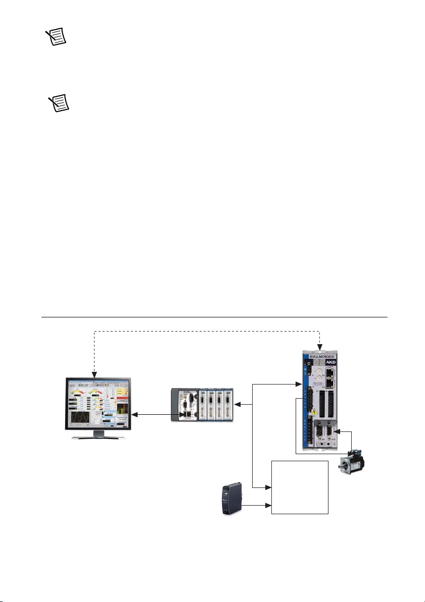
Figure 1 shows the required hardware and software.
Figure 1. Required Hardware and Software
Ethernet Cable
(Initial Configuration Only)
Ethernet
Cable
NI RT Controller
(NI cRIO-9014 shown)
and NI 9514/16 Module
+24 V Power Supply
(NI PS-15 Shown)
NI 9514/16 to
AKD Drive Cable
Screw Terminal
Connector for
Powe r Supply &
Additional I/O
(Limits, Position
Compare, etc.)
AKD Analog
Servo Drive
Getting Started with NI 9514/16 Modules and AKD Servo Drives | © National Instruments | 3
Page 4

Hardware Installation and Configuration
This section covers the hardware setup for the CompactRIO system, NI 9514 or NI 9516
C Series module, and AKD servo drive.
Figure 2 shows an overview of the connectors on the AKD servo drive.
Figure 2. AKD Servo Drive Connectors
12
1
2
3
11
10
9
8
7
6
4
5
1 24 V Supply, STO (X1)
2 Motor, Brake (X2)
3 AC Input Power (X3)
4 Encoder Emulation (X9)
4 | ni.com | Getting Started with NI 9514/16 Modules and AKD Servo Drives
5 Drive Grounding Lug
6 Feedback (X10)
7 I/O Connector (X8)
8 I/O Connector (X7)
9 Static IP Addressing Switch (S2)
10 Static IP Addressing Switch (S1)
11 Drive Communication (X11)
12 LED Indicators
Page 5
Step 1: Set Up the Real Time System
X9
MDR
Connector
DSUB
Connector
Screw Terminal
Connector
X1 3-Pin
Connector
X8 10-Pin
Connector
X9 DSUB
Connector
Complete the following steps to set up the CompactRIO hardware.
1. Refer to the Getting Started guide included with the Real-Time controller to assemble it,
connect it to power, discover it on the network, and install the software in NI MAX.
2. Install the NI 9514 or NI 9516 module in an available slot that supports High Speed
Interface (HSI) in your chassis.
Note Older model chassis, such as cRIO-902x, cRIO-907x, cRIO-908x, NI 9144,
and NI 9148, have HSI support on slots 1 through 4. Refer to your chassis
documentation for more information about HSI slot support.
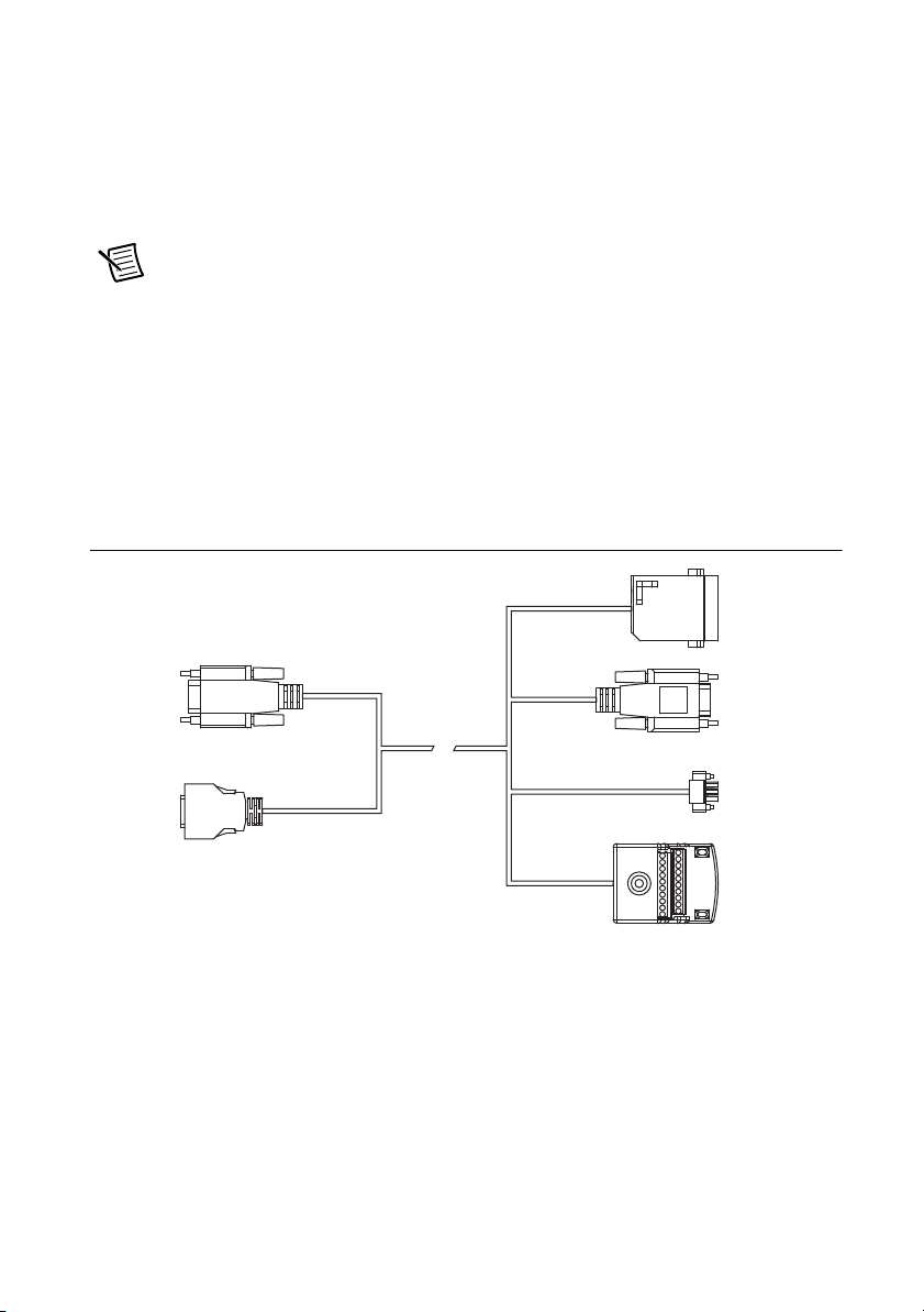
Step 2: Connect NI 9514/16 to AKD Drive Cable to the C Series Module
Connect the MDR and DSUB connectors on the NI 9514/16 to AKD Drive Cable (part number
781524-01) to the MDR and DSUB connectors on the C Series module. Figure 3 shows the
NI 9514/16 to AKD Drive Cable connectors.
Figure 3. NI 9514/16 to AKD Drive Cable Connectors
The NI 9514/16 to AKD Drive Cable contains the following connections:
• DSUB Connector—15-pin DSUB connector containing drive command and drive enable
signals.
• MDR Connector—20-pin MDR connector containing encoder, limit, home sensor,
position compare, and position capture signals.
• X8 10-Pin Connector—10-pin connector containing the servo command, enable, and fault
signals.
• X9 DSUB Connector—9-pin DSUB connector containing emulated encoder output
signals from the AKD servo drive.
Getting Started with NI 9514/16 Modules and AKD Servo Drives | © National Instruments | 5
Page 6

• X1 3-pin Connector—+24 V power supply connection for the AKD servo drive provided
through the 20-pin screw terminal connector.
• Screw Terminal Connector—20-pin screw terminal connector for external I/O
connections.
Table 1 shows the screw terminal I/O connector pinout.
Table 1. NI 9514/16 to AKD Drive Cable Screw-Terminal Pinout
Pin Signal Name
1 Forward Limit
2 Home
3 Reverse Limit
4 Digital Input 0
5 Vsup
6 Vsup Return
7 Encoder 1 Phase A+ (NI 9516 only)
8 Encoder 1 Phase A- (NI 9516 only)
9 Encoder 1 Phase B+ (NI 9516 only)
10 Encoder 1 Phase B- (NI 9516 only)
11 +5V OUT
12 Position Compare
13 Position Capture
14 COM
15 Reserved
16 Reserved
17 Reserved
18 Reserved
19 Reserved
20 Reserved
6 | ni.com | Getting Started with NI 9514/16 Modules and AKD Servo Drives
Page 7

Step 3: Mount the Drive and Connect the Protective Earth
1. Mount the drive to a conductive metal plate. Refer to the AKD Installation Manual for
dimensions and additional information specific to the drive model.
2. Connect the protective earth (PE) to either ground screw on the drive grounding lug.
Figure 2 shows the location of the grounding lug on the drive.
Step 4: Connect the Logic Power Supply to the NI 9514/16 to AKD Drive Cable
The NI 9514/16 to AKD Drive Cable requires connection to an external +24 V power supply.
The +24 V power supply provides both the logic power to the AKD servo drive and powers the
NI 9514 or NI 9516 module.
Note Do not plug in or turn on the +24 V power supply until after you complete the
steps in the Step 8: Connect the Drive Communication section.
Complete the following steps to connect the +24 V power supply to the cable.
1. Connect the +24 V power supply (+) terminal to the Vsup terminal on the NI 9514/16 to
AKD Drive Cable screw terminal connector.
2. Connect the +24 V power supply return (-) terminal to the Vsup Return terminal on the
NI 9514/16 to AKD Drive Cable screw terminal connector.
Step 5: Connect the NI 9514/16 to AKD Drive Cable to the AKD Servo Drive
Connect the NI 9514/16 to AKD Drive Cable to the AKD servo drive. Refer to Figure 2 for the
location of the connectors.
1. Connect the cable X1 3-pin connector to the AKD servo drive X1 3-pin connector. This
connector provides +24 V power to both the drive logic and to the safe torque out (STO)
input. The STO input must be powered by +24 V for proper drive operation. If you need to
use the STO functionality complete the following additional steps:
a. Disconnect the STO wire from the NI 9514/16 to AKD cable X1 connector and
insulate it.
Note The STO and +24V wires are internally connected in the NI 9514/16 to AKD
cable. You must insulate the STO wire if you disconnect it from the X1 connector.
b. Connect the STO terminal and GND terminal to the output of a safety relay or security
control. The safety relay must comply with the requirements of the SIL 2 according to
IEC 61800-5-2, PL d according to ISO 13849-1, or Category 3 according to EN-954.
Refer to the AKD Installation Manual for more information.
Getting Started with NI 9514/16 Modules and AKD Servo Drives | © National Instruments | 7
Page 8
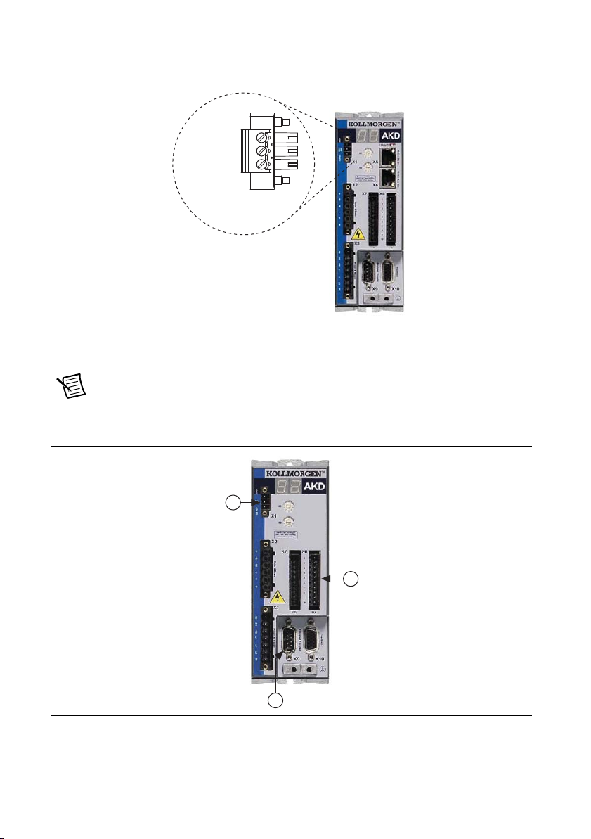
Figure 4 shows the X1 connector pin assignment and wire colors.
+24 V (Red)
GND (Black)
STO (Brown)
X1 3-Pin
Connector
1
2
3
Figure 4. AKD X1 Connector
2. Connect the cable X9 DSUB connector to the AKD servo drive X9 DSUB connector.
3. Connect the cable X8 10-pin connector to the AKD servo drive X8 10-pin connector.
Note You can use the X7 I/O connector for additional I/O but it is not used for
connection to the NI 9514 and NI 9516 drive interface modules.
Figure 5. NI 9514/16 to AKD Drive Cable Connections
1 +24 V Supply, STO (X1) 2 Encoder Emulation (X9) 3 I/O Connector(X8)
8 | ni.com | Getting Started with NI 9514/16 Modules and AKD Servo Drives
Page 9
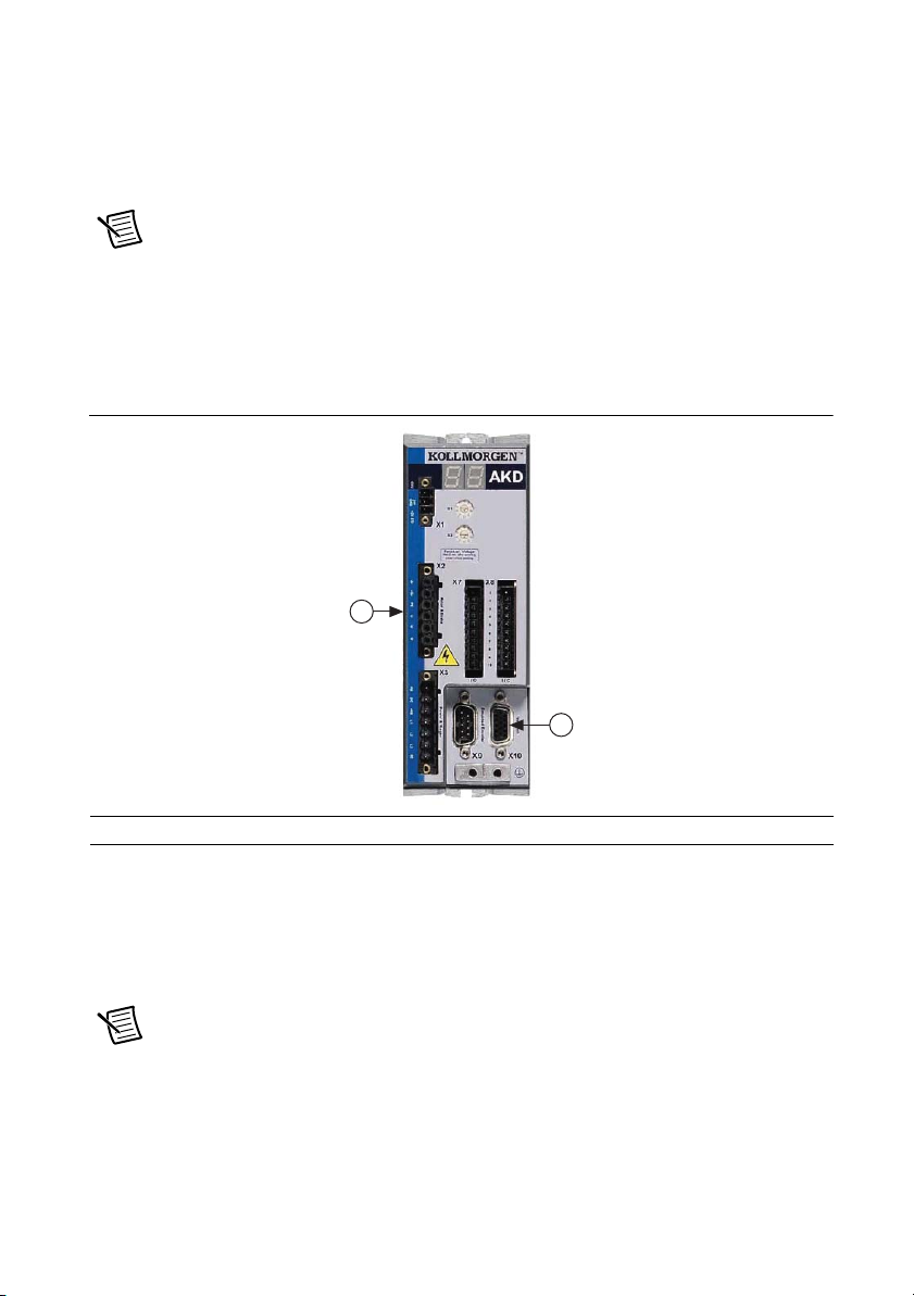
Step 6: Connect the Motor and Encoder to the Drive
1
2
All Kollmorgen AKM servo motors available from NI come pre-wired for direct connection to
the AKD servo drive X2 motor connector and X10 feedback connector. Refer to Figure 6 for the
location of the connectors.
1. Connect the motor 6-pin connector to the AKD servo drive X2 motor connector.
Note The X2 connector also provides connection for the drive to control the +24 V
holding brake for motors that have a brake. Refer to the AKD Installation Manual for
information about using the holding brake.
2. Connect the motor DSUB feedback connector to the AKD servo drive X10 feedback
connector.
Figure 6. Motor and Encoder Connections
1 Motor Connector (X2) 2 Feedback Connector (X10)
Step 7: Connect the AC Input Power
Connect the X3 mains supply connector to AC input power. Pins 4 through 7 contain the AC
power signals. The X3 connector also provides signals for an external brake (regen) resistor
(±RB) and DC bus link (-DC). Refer to the AKD Installation Manual for information about using
these terminals.
Note Do not turn on the AC power until after you complete Step 8: Connect the
Drive Communication section.
Getting Started with NI 9514/16 Modules and AKD Servo Drives | © National Instruments | 9
Page 10
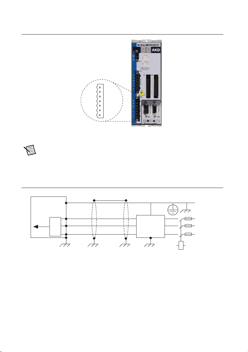
Figure 7 shows the location and pin assignment for the X3 connector.
1
2
3
4
5
6
7
–RB
–DC
+RB
L1
L2
L3
PE
Figure 7. AKD Servo Drive X3 Connector
AC input power can be connected for either a three-phase or single-phase operation.
Note External filtering and fusing are optionally provided by the user. Refer to the
AKD Installation Manual for information about filter and fuse requirements.
Figure 8 shows three-phase connection.
Figure 8. AC Input Power Three-Phase Connection
AKD Servo Drive
Protective
Earth
L1
DC
Out
10 | ni.com | Getting Started with NI 9514/16 Modules and AKD Servo Drives
L2
L3
User-Provided
(Optional)
Filter
Protective
Earth
L1
L2
L3
Page 11
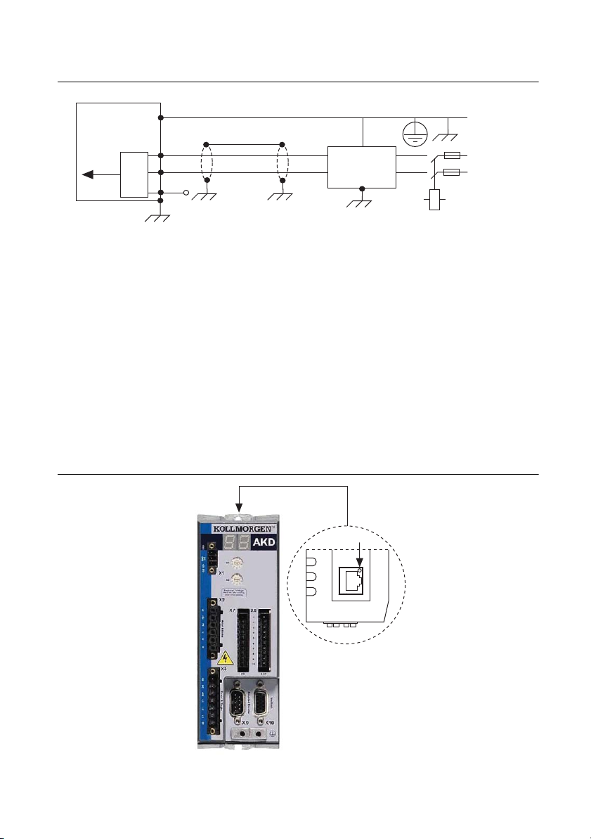
Figure 9 shows single-phase connection.
L1
User-Provided
Filter
(Optional)
L2
L3
L1
Neutral (L2)
Protective
Earth
Protective
Earth
DC
Out
AKD Servo Drive
LED
Figure 9. AC Input Power Single-Phase Connection
Step 8: Connect the Drive Communication
Complete the following steps to set up the drive for software configuration using Ethernet. These
steps assume you are connecting the AKD servo drive using a hub, switch, or router using
DHCP. If you cannot use DHCP, refer to the Connecting to the PC Using a Static IP section for
instructions about direct connection using a static IP address.
1. Set S1 and S2 on the drive to 0 to configure the drive for DHCP mode. The drive obtains
an IP address from an external DHCP server if one exists on the network. If no DHCP
server is present, the drive assumes an automatic private IP address in the form of
169.254.x.x. This process may take up to a minute to complete. Figure 2 shows the
locations of S1 and S2.
2. Connect the AKD servo drive X11 service port to a hub, switch, or router using an Ethernet
cable. Figure 10 shows the location of the X11 service port on the drive.
Figure 10. AKD Servo Drive X11 Connector
Getting Started with NI 9514/16 Modules and AKD Servo Drives | © National Instruments | 11
Page 12

Step 9: Confirm Drive Connections
After all hardware connections have been made complete the following steps to confirm the
AKD hardware setup.
1. Apply AC power.
2. Turn on the +24 V power supply. After logic power is supplied to the drive, the drive
displays the following sequence of flashes in the LED indicators. Figure 2 shows the
location of the LED indicators on the AKD servo drive.
a. - -
b. [ ]
c. Drive IP address, flashed sequentially
d. Drive status, either current operation mode or the fault code if there is a fault
condition. The operation modes are as follows:
• o0—torque mode (current mode)
• o1—velocity mode
• o2—position mode
Note If the drive shows a fault code, click the Clear Faults button on the AKD
WorkBench software toolbar after you install the AKD WorkBench software in
Step 5: Install AKD WorkBench and Configure the Drive section and connect to the
drive to clear the fault state. If the fault reappears, refer to the AKD Fault and
Warning Messages Card that came with the drive for more information about the
fault, including possible solutions. After resolving the cause of the fault, click the
Clear Faults button on the toolbar again. Figure 17 shows the location of the Clear
Faults toolbar button in the AKD WorkBench software.
Software Installation and Configuration
This section covers installing and configuring the software for the AKD servo drive and NI 9514
or NI 9516 C Series modules.
Step 1: Install Software on and Configure the NI RT Controller
Complete the following steps to configure the controller and install software on it.
1. Launch Measurement & Automation Explorer (MAX) on the development computer by
clicking the MAX icon on the desktop, or by selecting Start»All Programs»National
Instruments»NI MAX.
2. Select the controller under Remote Systems in the Configuration pane. If you do not see
the controller, you may need to disable the firewall on the development computer.
3. Verify that the Serial Number in the Identification section matches the serial number on
the device.
12 | ni.com | Getting Started with NI 9514/16 Modules and AKD Servo Drives
Page 13

4. Expand the controller item in the tree, right-click Software, and select Add/Remove
Software.
5. Select a recommended software set that includes NI-RIO 3.4.0 or later with NI Scan Engine
Support.
6. Click Next and enable the following add-ons:
• LabVIEW SoftMotion Module
• NI Industrial Communications for EtherCAT if using the NI 9144.
Note If you are using the LabVIEW SoftMotion Module 2010 SP1 or earlier, you
need to install NI Scan Engine Support for LabVIEW SoftMotion Module.
7. Click Next to install the selected software on the controller. Click Help if you need
information about installing recommended software sets.
8. Close MAX.
Step 2: Creating a Project and Adding NI RT Controller
Complete the following steps to create a LabVIEW project.
1. Launch LabVIEW by selecting Start»All Programs»National Instruments»LabVIEW.
2. Click the Empty Project link in the Getting Started window to display the Project
Explorer window. You can also select File»New Project to display the Project Explorer
window.
3. Select Help and make sure that Show Context Help is checked. You can refer to the
context help throughout the tutorial for information about items on the block diagram.
Depending on the hardware configuration being used, continue to the following respective
sections.
A. CompactRIO Controller
If you are using a CompactRIO controller, complete the following steps to add the device to the
project and detect the C Series modules.
1. Right-click the top-level project item in the Project Explorer window and select New»
Targets and Devices from the shortcut menu to display the Add Targets and Devices
dialog box.
2. Make sure that the Existing target or device radio button is selected.
3. Expand Real-Time CompactRIO.
4. Select the CompactRIO controller to add to the project and click OK.
5. If you have LabVIEW FPGA installed, the Select Programming Mode dialog box
appears. Select Scan Interface to put the system into Scan Interface mode.
Tip Use the CompactRIO Chassis Properties dialog box to change the
programming mode in an existing project. Right-click the CompactRIO chassis in the
Project Explorer window and select Properties from the shortcut menu to display
this dialog box.
Getting Started with NI 9514/16 Modules and AKD Servo Drives | © National Instruments | 13
Page 14

6. Click Discover in the Discover C Series Modules? dialog box if it appears.
7. Click Continue.
8. Right-click the controller item in the Project Explorer window and select Properties from
the shortcut menu to display the RT Target Properties dialog box. Select Scan Engine
from the Category list to display the Scan Engine page.
9. Set the Scan Period to 5 ms or lower, then click OK to close the RT Target Properties
dialog box.
B. EtherCAT Master and NI 9144 EtherCAT Expansion Chassis
If you are using the NI 9144 chassis, complete the following steps to add the EtherCAT master
device and detect the C Series modules.
1. Add the Master Real Time Controller to the project. Right click the top level project item
in the Project Explorer window and select New»Targets and Devices from the shortcut
menu to display the Add Targets and Devices dialog box.
2. Make sure that Existing target or device radio button is selected.
3. Expand the folder that corresponds to the device you are adding, such as Real Time
Industrial Controller, Real Time PXI, and so on.
4. Select the Real Time to add to the project and click OK.
5. In the LabVIEW Project Explorer window, right-click the master controller and select
New»Targets and Devices.
6. In the Add Targets and Devices dialog window shown in Figure 11, select Existing target
or device and expand the category EtherCAT Master Device to auto-discover the EtherCAT
port on the master controller. An EtherCAT master device and modules can be added
manually at any time.
Figure 11. Adding the EtherCAT Master
When all the slave devices are discovered, the LabVIEW Project Explorer window lists each
slave device and any installed C Series modules.
14 | ni.com | Getting Started with NI 9514/16 Modules and AKD Servo Drives
Page 15

C. NI 9146/7/8/9 Ethernet RIO Expansion Chassis
Complete the following steps to add the device to the project and detect the C Series modules if
the NI 9146/7/8/9 Ethernet RIO Expansion chassis is being used.
1. Right-click the top-level project item in the Project Explorer window and select New»
Targets and Devices from the shortcut menu to display the Add Targets and Devices
dialog box.
2. Make sure that the Existing target or device radio button is selected.
3. Expand Ethernet RIO.
4. Select the Ethernet RIO expansion chassis to add to the project and click OK.
5. If you have LabVIEW FPGA installed, the Select Programming Mode dialog box
appears. Select Scan Interface to put the system into Scan Interface mode.
Tip Use the Chassis Properties dialog box to change the programming mode in an
existing project. Right-click the chassis in the Project Explorer window and select
Properties from the shortcut menu to display this dialog box.
6. Click Discover in the Discover C Series Modules? dialog box if it appears.
7. Click Continue.
8. Right-click the controller item in the Project Explorer window and select Properties from
the shortcut menu to display the Ethernet RIO Properties dialog box. Select Scan Engine
from the Category list to display the Scan Engine page.
9. Set the Scan Period to 5 ms or lower, then click OK to close the Ethernet RIO Properties
dialog box.
Step 3: Adding an NI SoftMotion Axis to the Project
Complete the following steps to create a LabVIEW project.
1. Right-click the controller item in the Project Explorer window and select New»NI
SoftMotion Axis from the shortcut menu to open the Axis Manager dialog box, shown in
Figure 12.
2. Click Add New Axis to create an NI SoftMotion axis associated with the NI 9514 or
NI 9516 module. Axes are automatically bound to an available module. You can
double-click the axis name to rename the axis and give it a descriptive name.
Getting Started with NI 9514/16 Modules and AKD Servo Drives | © National Instruments | 15
Page 16

Figure 12. Axis Manager Dialog Box
3. Click OK to close the Axis Manager dialog box. The new axis is added to the Project
Explorer window.
Note You cannot associate more than one axis with the same C Series module.
When you have finished these steps your LabVIEW project should look similar to the
image in Figure 13.
Figure 13. Project Explorer Windows with Modules in Scan Interface Mode
16 | ni.com | Getting Started with NI 9514/16 Modules and AKD Servo Drives
Page 17

Step 4: Configure the NI 9514 or NI 9516 C Series Modules
Complete the following steps to configure the axis I/O settings for use with the AKD servo drive.
1. Right-click the axis in the Project Explorer window and select Properties from the
shortcut menu to open the Axis Configuration dialog box.
Figure 14 shows the parts of the Axis Configuration dialog box for NI 9514 and NI 9516
C Series modules.
Figure 14. Axis Configuration Dialog Box
Note The Axis Configuration dialog box user interface may not match this image
exactly depending on which version of the LabVIEW NI SoftMotion Module you are
using.
2. Click the Digital I/O button to open the Digital I/O page and map DI 1 to Drive
Fault/Alarm.
Getting Started with NI 9514/16 Modules and AKD Servo Drives | © National Instruments | 17
Page 18

a. Double-click the text in the Mapping column and select Drive Fault/Alarm from the
dropdown list.
b. Ensure that the DI 1 settings match the following:
• Input Type—Sinking
• Active State—Off
• Digital Filter—50 µs
3. Open the Drive Enable page and ensure that the Drive Enable settings match the following:
• Output Type—Sourcing
• Active State—On
• Safe State—Off
4. Complete the following additional steps if you do not have limits and home connected at
this time:
a. Open the Limits & Home page.
b. In the Forward Limit and Reverse Limit sections ensure that the settings match the
following:
Note These configuration settings disable limits for initial setup and testing
purposes. National Instruments recommends connecting and enabling limits in your
final application.
• Clear the Enable checkbox from both Forward Limit and Reverse Limit.
• Set the Active State for both Forward Limit and Reverse Limit to Off. This
prevents a limit warning even though limits are turned off.
c. Open the Home section and clear the Enable checkbox.
5. Open the Position Loop page and make the following changes in the Gains section:
•Set Kp to 50.
•Set Kd to 1000.
•Set Ki to 0.
Note These values do not result in a properly tuned motor, but may allow you to
perform a simple move for testing purposes. After connecting the other mechanical
18 | ni.com | Getting Started with NI 9514/16 Modules and AKD Servo Drives
Page 19

elements of the system, use the Gain Tuning Panel to tune the control loop settings
and determine the relative stability of the servo axis. Refer to the Using the Gain
Tuning Panel topic in the NI SoftMotion Module book of the LabVIEW Help for
detailed information about the Gain Tuning Panel and servo system tuning
instructions.
6. Open the Encoder page.
•In the Active State section set the Line State for A, B, and Index to High.
•In the Index Reference Criteria section set the Line State for A and B to
Active.
• Type revolution in the Units text box.
• Set the Counts per Unit to 8,000. This setting is the encoder resolution in
quadrature counts per revolution and must correspond to the AKD WorkBench
emulated encoder output Resolution setting in lines per revolution multiplied
by four. You may want to choose a different resolution depending on your
application needs. Changing this setting allows moves to be commanded in units
of revolutions per second.
Note You configure the emulated encoder output Resolution setting in Step 5:
Install AKD WorkBench and Configure the Drive section.
When you are finished the Encoder Settings page will look similar to Figure 15.
Figure 15. Axis Configuration Encoder Page
7. Configure any additional I/O settings according to your system requirements.
8. Click OK to close the Axis Configuration dialog box.
9. Right-click the controller item in the Project Explorer window and select Deploy All to
deploy the axis information.
10. Select File»Save Project to save the project.
Getting Started with NI 9514/16 Modules and AKD Servo Drives | © National Instruments | 19
Page 20

Step 5: Install AKD WorkBench and Configure the Drive
AKD WorkBench is available on the CD that came with the AKD servo drive and is also
available from
drive settings with AKD WorkBench.
1. Insert the AKD WorkBench CD in the CD-ROM drive on your PC.
2. Double-click
3. Follow the onscreen instructions to complete the installation.
4. Launch the AKD WorkBench software by clicking the AKD WorkBench icon on the
desktop, or by selecting Start»All Programs»Kollmorgen»AKD WorkBench.
5. Select the drive to configure from the list and click Connect.
ni.com/updates. Complete the following steps to install and configure the
Full Setup.exe to launch the installer.
Note If the drive is not in the list, refer to the Tips and Troubleshooting section of
this document for possible solutions.
20 | ni.com | Getting Started with NI 9514/16 Modules and AKD Servo Drives
Page 21

Figure 16 shows the AKD WorkBench start page.
Figure 16. AKD WorkBench Start Page
1
1 Available Drives 2 Specify Address 3 Connect to Drive
2
3
Getting Started with NI 9514/16 Modules and AKD Servo Drives | © National Instruments | 21
Page 22

6. (Optional) Change the name of the drive from the default name of no_name on the AKD
Overview page to a more descriptive name.
Figure 17 shows the AKD Overview page.
Figure 17. AKD WorkBench Overview Page
1
2
7 8109
3
4 5
6
1 Software Enable/Disable
2 Command Source
3 Operation Mode
4 Clear Faults
5 Save Configuration Settings to Drive
22 | ni.com | Getting Started with NI 9514/16 Modules and AKD Servo Drives
6 Software Enable/Disable
7 Drive Active Indicator
8 Software Enable Status Indicator
9 Hardware Enable Status Indicator
10 Fault Indicator
Page 23

7. Configure the command source and operation mode.
1
2
a. Open the Settings page and set the Command Source to 3 - Analog.
b. Set the Operation Mode to 0 - Torque Mode.
When you have updated these settings the Settings page should look similar to
Figure 18.
Figure 18. AKD WorkBench Settings Page
1 Command Source Setting 2 Operation Mode Setting
8. Configure the emulated encoder output.
a. Expand the Settings tree item and open the Encoder Emulation page.
b. Select 1- Output - With once per rev index pulse from the Function dropdown list.
c. Set the Resolution to 2,000 lines/rev.
Note The encoder resolution output value determines the equivalent resolution of
an incremental encoder in pulses per revolution (PPR). NI SoftMotion returns
encoder positions in encoder counts per revolution. A resolution of 2,000 lines/rev is
the same as 8,000 quadrature counts per revolution.You may want to choose a
different value depending on your application needs. In general, higher resolution
values result in more difficult servo loop tuning; lower resolution values provide less
Getting Started with NI 9514/16 Modules and AKD Servo Drives | © National Instruments | 23
Page 24

accuracy. If you select a different value for Resolution, remember to update the
Counts Per revolution setting in the Axis Configuration dialog box.
d. Set the Index Offset to 0.
Figure 19 shows the AKD WorkBench Encoder Emulation page.
Figure 19. AKD WorkBench Encoder Emulation Page
9. Configure the analog input command scaling.
a. Expand the Settings tree item and open the Motor page.
b. Write down the motor Continuous Current value.
Note Motor continuous current is in Arms.
24 | ni.com | Getting Started with NI 9514/16 Modules and AKD Servo Drives
Page 25

Figure 20 shows the AKD WorkBench Motor page.
Figure 20. AKD WorkBench Motor Page
c. Expand the Settings tree item and open the Analog Input page.
d. Set the Scale to the appropriate Arms/V value based on the following equation:
Scale = Motor continuous current / 10
For example, if you have a motor with a maximum current of 3.00 Arms set Scale to
0.3 Arms/V.
Getting Started with NI 9514/16 Modules and AKD Servo Drives | © National Instruments | 25
Page 26

Figure 21 shows the analog input scaling setting.
Figure 21. AKD WorkBench Analog Input Scale Setting
10. Configure the software enable signal:
a. Click the Parameters tree icon to list all configurable drive parameters.
b. Expand the Drive section.
c. Set the Software enable default parameter to 1.
26 | ni.com | Getting Started with NI 9514/16 Modules and AKD Servo Drives
Page 27

Figure 22 shows the AKD WorkBench parameters page.
Figure 22. AKD WorkBench Parameters Page
11. Activate the software enable on the drive by clicking the Enable button on the AKD
Overview page or on the toolbar. Figure 17 shows the location of the Enable button.
12. Save all configuration changes to the drive by clicking the Save to Drive toolbar button
shown in Figure 17.
Step 6: Enable and Test the Drive using LabVIEW
Use the Interactive Test Panel to test and debug your motion system and configuration settings
on the selected axis. With the Interactive Test Panel you can perform a simple straight-line
move, monitor feedback position and position error information, I/O and move status
information, change move constraints, get information about software errors and faults,
and view position or velocity plots of the move.
Caution The test parameters in this steps assume that the units have been scaled to
revolutions as described in the preceeding step. If the motor is already connected to
a mechanical system, ensure that moving the motor shaft for 10 revolutions at
1 revolution per second will not damage any components.
Getting Started with NI 9514/16 Modules and AKD Servo Drives | © National Instruments | 27
Page 28

Complete the following steps to test your setup after configuring and tuning the axis.
1. Right-click the axis in the Project Explorer window and select Interactive Test Panel
from the shortcut menu. Opening this dialog box sends the axis settings to the hardware and
activates the I/O on the module.
2. On the Move tab, set the Target Position to 10.
3. On the Move Constraints tab, configure the following settings:
a. Set Velocity to
b. Set Acceleration to 10.00 Rev/sec^2
c. Set Deceleration to
d. Set Acceleration Jerk to
e. Set Deceleration Jerk to 100.00 Rev/sec^3
4. Click the Start button on the bottom of the dialog box. The move should proceed for
10 revolutions at a velocity of 1 revolution per second.
5. Use the Status and Plots tabs to monitor the move while it is in progress.
6. Finalize the motion system setup by connecting and configuring additional I/O such as
limits as required by your system using the 20-pin screw terminal connector. Table 1 shows
the screw-terminal connector pinout.
7. Tune the motor with a load connected using the Gain Tuning Panel dialog box. Refer to
the Using the Gain Tuning Panel topic in the NI SoftMotion Module book of the LabVIEW
Help for detailed information about the Gain Tuning Panel and servo system tuning. In the
eth0 (Primary) section click More Settings and change Packet Detection to Polling.
Leave the Polling Interval at 1 ms.
1.00 Rev/sec
10.00 Rev/sec^2
100.00 Rev/sec^3
Tips and Troubleshooting
The Drive Does Not Enable
If, after going through all steps in this document, the AKD servo drive does not enable, verify
the following settings:
• The Drive Enable line from the NI 9514 or NI 9516 C Series module must be active.
Figure 17 shows the location of the hardware enable indicator in the AKD WorkBench
software.
• The software enable must be enabled. This setting is available on the upper toolbar in the
AKD WorkBench software. Figure 17 shows the location of the software enable indicator
and toolbar button.
• The drive must not be in a fault state. Click the Clear Faults button on the toolbar to clear
the fault state after determining and fixing the source of the fault. Figure 17 shows the
location of the Fault indicator and Clear Faults toolbar button.
Tip Refer to the AKD Fault and Warning Messages card that came with the drive
for fault information and solutions.
28 | ni.com | Getting Started with NI 9514/16 Modules and AKD Servo Drives
Page 29

Using an EtherCAT AKD Drive in Analog Mode
If an EtherCAT AKD Drive is being used in Analog mode with firmware version
M_01-04-00-003 or later, the FBUS.PARAM.05 must be set to 4. This keeps the Software
Enable setting as active after the Hardware Enable is disabled. Complete the following steps to
set the FBUS.PARAM.05 parameter.
1. Click Parameters icon to list all configurable drive parameters.
2. Expand the Fieldbuses section.
3. Set the FBUS.PARAM.05 parameter to 4.
4. Save all configuration changes to the drive by clicking the Save To Drive button.
Figure 23 shows the Fieldbuses section of the AKD Workbench parameters page.
Figure 23. AKD WorkBench Fieldbuses Section
Cannot Communicate With the Drive Using Ethernet
Confirm that the link LEDs on the drive and PC are both illuminated. Figure 10 shows the
location of the link LED on the drive.
Getting Started with NI 9514/16 Modules and AKD Servo Drives | © National Instruments | 29
Page 30

Connecting to the PC Using a Static IP
X11
B1
1. Use the S1 and S2 rotary switches on the drive to set a static IP address. The IP address is
192.168.0.S1S2. For example, if S1 is set to 2 and S2 is set to 3 the IP address is
192.168.0.23.
Note If you change S1 or S2 when the +24 V power supply is powered on, you must
unplug the network cable from the drive for at least three seconds to reset the IP
address.
2. Connect the AKD servo drive to the computer directly using an Ethernet cable. Figure 10
shows the location of the X11 service port on the drive.
3. Select Start»Control Panel»Network Connections to open the Network Connections
dialog box.
4. Select the network connection type corresponding to the port you used to connect the AKD
servo drive. This will most likely be Local Area Connection.
5. Click Properties, then select Internet Protocol (TCP/IP) from the list.
6. In the Internet Protocol (TCP/IP) dialog box, select Use the following IP address.
7. Change IP address to
8. Change Subnet mask to
Verify that S1 and S2 are set to non-zero values.
198.168.0.100.
255.255.255.0.
The Motor Responds Poorly
Use the Gain Tuning Panel dialog box to change the control loop settings for the motor. Refer
to the Using the Gain Tuning Panel topic in the NI SoftMotion Module book of the LabVIEW
Help for detailed information about the Gain Tuning Panel and servo system tuning instructions.
Cannot See the AKD Servo Drive in the AKD WorkBench Software
Manually enter the drive IP address by enabling the Specify Address checkbox on the AKD
WorkBench software Start Page shown in Figure 16. To obtain the drive IP address either press
the B1 button on the top of the drive or disconnect and reconnect the Ethernet cable. In either
case, the LED displays the digits and dots of the IP address in sequence. Figure 24 shows the
location of the B1 button.
Figure 24. AKD Servo Drive B1 Button
30 | ni.com | Getting Started with NI 9514/16 Modules and AKD Servo Drives
Page 31

Wiring Diagram
Figure 25. AKD Wiring Diagram
Reference Safety Instructions
and Use As Directed
Thermal Control
Included
Feedback
B–
B+
PE
U1
M
V1
W1
F
Regeneration
Resistor
Filter
B1
F
B2
+–
Supply Unit
24 V DC
1
2
3
4
5
6
1
2
3
4
5
6
7
1
3
2
Feedback
– Br
+ Br
PE
U
V
W
– RB
– DC
+ RB
L1
L2
L3
PE
+ 24 V
STO
GND
(
+ DC
X2
X3
)
X1
X7X10
DIGITAL–IN7
DIGITAL–IN4
DIGITAL–IN3
DIGITAL–OUT2
DIGITAL–OUT2
DIGITAL–OUT1
DIGITAL–OUT1
DIGITAL–IN2
DIGITAL–IN1
X8
Fault
ENABLE
DIGITAL–IN6
(NSTOP)
DIGITAL–IN5
(PSTOP)
Analog–Out +
Analog–In –
Analog–In +
DGND
DGND
AGND
Control
+ 24 V Referred
1
2
3
4
5
–
6
+
7
–
8
+
9
10
1
2
3
4
5
6
7
8
9
10
to I/O GND
I/O–GND
I/O–GND
–
+
–
+
Digital2
Digital1
Emergency
Stop Circuit
+ 24V Ref
to I/O GND
Tachometer
Vol tage
+/– 10 V
+/– 10
V Speed
Setpoint
Referred to
I/O–GND
+
+
erred
Mains
Contactor
FN1FN2F
N3
L1 L2 L3 PE
FH1FH2F
X9
X11
Encoder
Emulation
TCP/IP
H3
9
8
PE–Connection (Protective Earth)
Chassis Ground Connection (Panel)
Shield Connection Via Plug
Encoder
Evaluation
Service
Getting Started with NI 9514/16 Modules and AKD Servo Drives | © National Instruments | 31
Page 32

Where to Go From Here
The following documents contain additional information that you may find helpful. All
referenced documents are available at
• Operating instructions for the controller and C Series modules.
• AKD Installation Manual—Use this document to learn additional information about the
electrical and mechanical aspects of the AKD servo drive, including important safety
information.
• LabVIEW NI SoftMotion Module Help—Use this help file to learn about using the
NI SoftMotion Module in LabVIEW including information about function blocks and
using the NI SoftMotion Module with the LabVIEW Project. To access this help file from
LabVIEW, select Help»LabVIEW Help, then expand the LabVIEW NI SoftMotion
Module book on the Contents tab.
• Setup Guide for Ethernet RIO Expansion Chassis—Use this document to learn additional
information about how to connect the NI 9144 chassis to a network, how to use the NI 9144
chassis features, and contains the NI 9144 chassis specifications.
• NI Industrial Communications for EtherCAT software documentation at
ni.com/manuals.
ni.com.
32 | ni.com | Getting Started with NI 9514/16 Modules and AKD Servo Drives
Page 33

Worldwide Support and Services
The NI website is your complete resource for technical support. At ni.com/support you have
access to everything from troubleshooting and application development self-help resources to
email and phone assistance from NI Application Engineers.
ni.com/services for NI Factory Installation Services, repairs, extended warranty, and
Vis it
other services.
ni.com/register to register your NI product. Product registration facilitates technical
Vis it
support and ensures that you receive important information updates from NI.
A Declaration of Conformity (DoC) is our claim of compliance with the Council of the European
Communities using the manufacturer’s declaration of conformity. This system affords the user
protection for electromagnetic compatibility (EMC) and product safety. You can obtain the DoC
for your product by visiting
you can obtain the calibration certificate for your product at ni.com/calibration.
NI corporate headquarters is located at 11500 North Mopac Expressway, Austin, Texas,
78759-3504. NI also has offices located around the world. For telephone support in the United
States, create your service request at
For telephone support outside the United States, visit the Worldwide Offices section of
ni.com/niglobal to access the branch office websites, which provide up-to-date contact
information, support phone numbers, email addresses, and current events.
ni.com/certification. If your product supports calibration,
ni.com/support or dial 1 866 ASK MYNI (275 6964).
Getting Started with NI 9514/16 Modules and AKD Servo Drives | © National Instruments | 33
Page 34

Refer to the NI Trademarks and Logo Guidelines at ni.com/trademarks for more information on NI trademarks. Other product and company
names mentioned herein are trademarks or trade names of their respective companies. For patents covering NI products/technology, refer to the
appropriate location: Help»Patents in your software, the patents.txt file on your media, or the National Instruments Patents Notice at
ni.com/patents. You can find information about end-user license agreements (EULAs) and third-party legal notices in the readme file for your
NI product. Refer to the Export Compliance Information at ni.com/legal/export-compliance for the NI global trade compliance policy
and how to obtain relevant HTS codes, ECCNs, and other import/export data. NI MAKES NO EXPRESS OR IMPLIED WARRANTIES AS TO THE
ACCURACY OF THE INFORMATION CONTAINED HEREIN AND SHALL NOT BE LIABLE FOR ANY ERRORS. U.S. Government Customers: The data
contained in this manual was developed at private expense and is subject to the applicable limited rights and restricted data rights as set forth in
FAR 52.227-14, DFAR 252.227-7014, and DFAR 252.227-7015.
© 2010–2016 National Instruments. All rights reserved.
375516E-01 Jun16
 Loading...