

Page 1
N707AU/STE
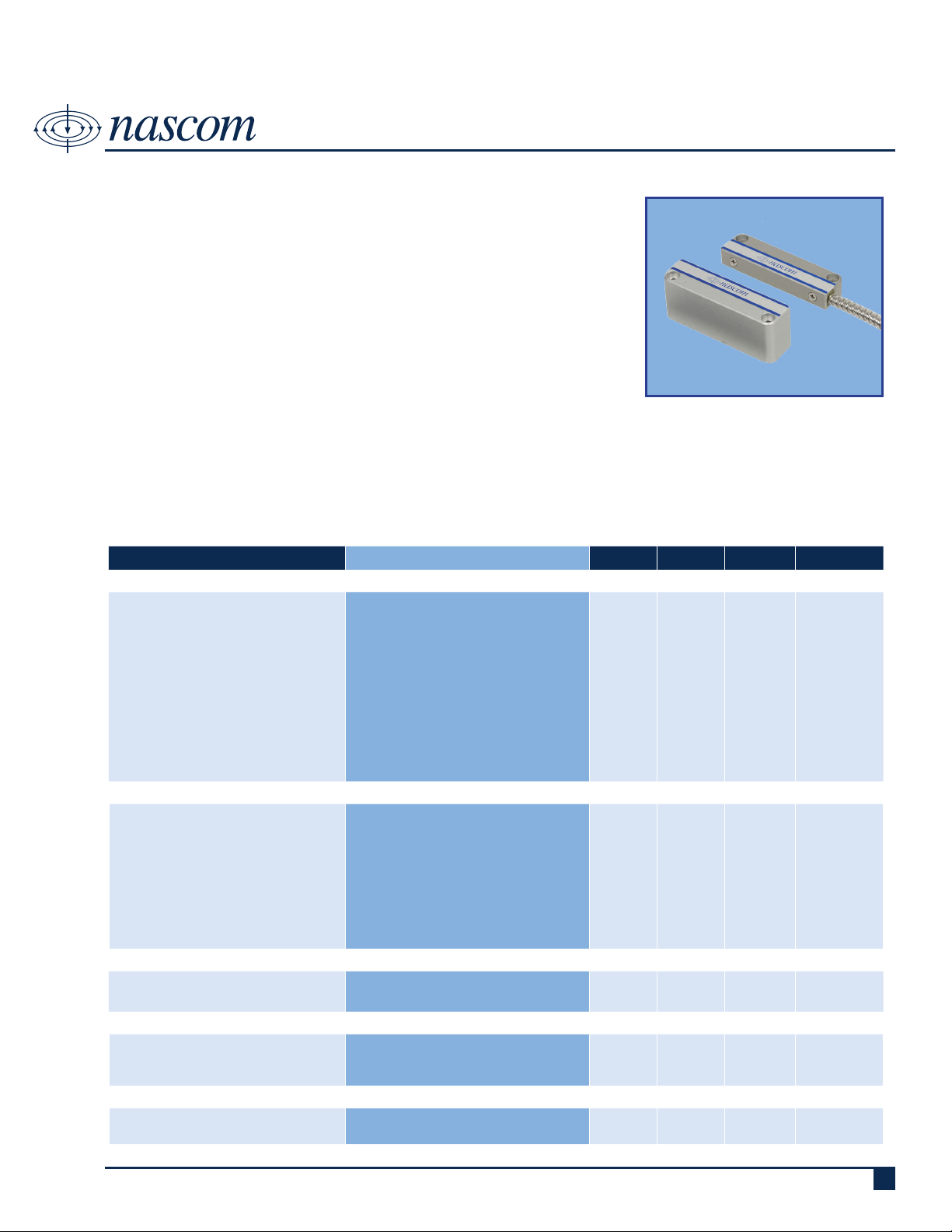
BALANCED MAGNETIC SWITCH LEVEL 2 – ELECTRIC DOOR STRIKE
DESCRIPTION
Nascom’s High Security UL Level 2 BMS, patent pending design utilizes
multiple magnetic elds; providing the most advanced magnetic high security
switch in the world. Applications include government facilities, bank safes and
vaults.
The N707AU/STE Model BMS prevents false alarms on doors with electric
door strikes; maintaining the door in a secure state while allowing some limited movement of the door in the latched position.
FEATURES
• SMALL FOOTPRINT • ANODIZED ALUMINUM SWITCH AND MAGNET HOUSING
• DOUBLE RESISTANT TAMPER • EPOXY ENCAPSULATED HERMETICALLY SEALED CONTACTS
• UNIVERSAL MOUNT - LEFT OR RIGHT • LISTED TO UL634 STANDARD
• 24” ARMORED CABLE (STANDARD) • SUITABLE FOR INDOOR OR OUTDOOR USE
SPECIFICATIONS
PARAMETERS CONDITION MIN TYP MAX UNITS
CONTACT RATINGS — ALARM CIRCUIT
Operate Gap
Release Gap
Side-to-side offset
Front-to-back offset Operate
Front-to-back offset Release
Switching Voltage
Switching Current
Carry Current
Contact Rating
Life Expectancy
Static Contact Resistance
Contact Material
Max DC/Peak AC Resistive
Max DC/Peak AC Resistive
Max DC/Peak AC Resistive
Max DC/Peak AC Resistive
1V, 10mA Signal Level
50mV, 10mA
CONTACT RATINGS — TAMPER CIRCUIT
Operate Gap
Release Gap
Switching Voltage
Switching Current
Carry Current
Contact Rating
Life Expectancy
Static Contact Resistance
Contact Material
With spaces under switch and magnet
Max DC/Peak AC Resistive
Max DC/Peak AC Resistive
Max DC/Peak AC Resistive
Max DC/Peak AC Resistive
1V, 10mA Signal Level
50mV, 10mA
0.000
0.125
0.000
1.00E+06
Au
1.00E+06
Au
0.125
0.150
0.125
0.625
0.750
30
0.020
0.020
0.600
400
0.125
0.093
30
0.020
0.020
0.600
400
inches
Inches
Inches
Inches
Inches
VDC
Amps
Amps
VA
Ops
mOhms
Inches
Inches
VDC
Amps
Amps
VA
Ops
mOhms
CIRCUIT INFORMATION
Alarm Circuit
Tamper Circuit
SWITCH SPECIFICATIONS
Insulation Resistance
Capacitance
Dielectric Strength
ENVIRONMENTAL RATINGS
Storage Temperature
Operating Temperature
Royne Industries LLC, dba Nascom
Closed Loop / Normally Open
Closed Loop / Normally Open
100V, 25oC, 40% RH
Across Open Contacts
Between Contacts
|
P: 800.843.5530
|
F: 800.727.4041
1.00E+09
250
-35
-35
+66
+66
|
www.nascominc.com
Ohms
VDC/PeakAC
o
C
o
C
DWG No. 12009-15 Rev. 3
1
Page 2
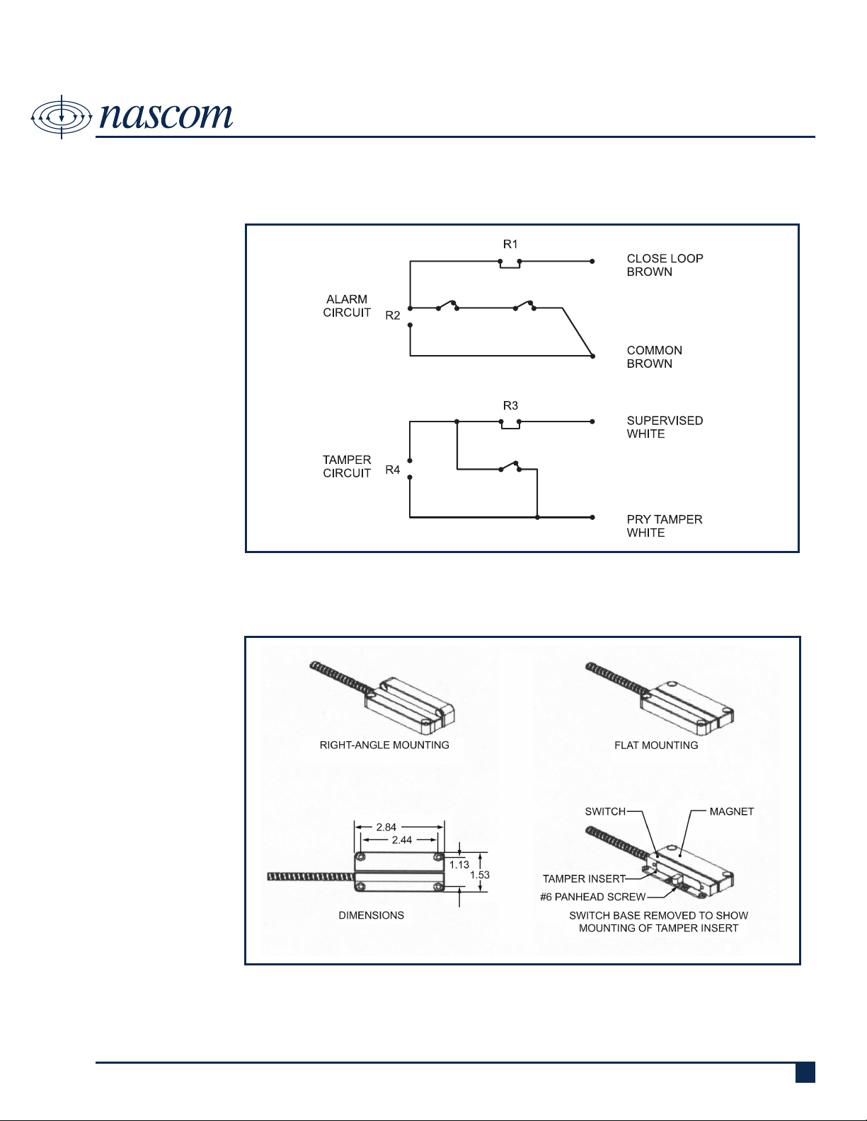
WIRING SCHEMATIC
N707AU/STE
BALANCED MAGNETIC SWITCH LEVEL 2 – ELECTRIC DOOR STRIKE
DIMENSIONS - IN [mm]
Royne Industries LLC, dba Nascom
|
P: 800.843.5530
|
F: 800.727.4041
|
www.nascominc.com
DWG No. 12009-15 Rev. 3
2
Page 3

ORDERING INFORMATION
PART NUMBER DESCRIPTION
N707AU/STE
N707AU/STEATS
N707AU/SWE
N707AU/SWEATS
N707AU/ME
N707AUSPKIT
N707AU/STER1xx
N707AU/STER1xxR2xx
N707AU/STER3
N707AU/STER3xxR4xx
N707AU/STER1xxR3xxR4xx
N707AU/STER1xxR2xxR3xx
N707AU/STER1xxR3xx
N707AU/STER1xxR2xxR3xxR4xx
EXAMPLE:
N707AU/STER11KR21KR31KR41K
Switch and e-strike magnet set
Switch and e-strike magnet set with alarm and tamper circuits connected in series
Switch only
Switch with alarm and tamper circuits connected in series
E-strike magnet only
Spacer kit
Switch and e-strike magnet set with alarm circuit resistor in series — xx=resistor value
Switch and e-strike magnet set with alarm circuit R1 resistor in series and R2 resistor in parallel — xx=resistor
value
Switch and e-strike magnet set with tamper circuit resistor in series — xx=resistor value
Switch and e-strike magnet set with tamper circuit R1 resistor in series and R2 resistor in parallel — xx=resistor
value
Switch and e-strike magnet set with alarm circuit resistor in series and tamper circuit R1 resistor in series and
R2
resistor in parallel — xx=resistor value
Switch and e-strike magnet set with alarm circuit R1 resistor in series and R2 resistor in parallel and tamper
circuit resistor in series — xx=resistor value
Switch and e-strike magnet set with alarm and tamper circuits resistor in series — xx=resistor value
Switch and e-strike magnet set with alarm and tamper circuit R1 resistor in series and R2 resistor in parallel —
xx=resistor value
N707AU E=Strike set with alarm circuit 1K resistor in series, 1K resistor in parallel, and tamper circuit 1K
resistor in series, 1 K resistor in parallel
N707AU/STE
BALANCED MAGNETIC SWITCH LEVEL 2 – ELECTRIC DOOR STRIKE
INSTALLATION INSTRUCTIONS
This level 2 BMS is to be connected / used with UL Listed Burglar Panels / Systems, Switch and Magnet must be
aligned for corrrect operation!
WOOD DOORS — NON FERROUS APPLICATIONS:
Mount in desired location and orientation using #6 pan-head screws with a minimum recommended length of 1/2 inch.
To ensure the highest security, keep the gap as small as practical. A 1/32” gap is recommended but the switch will operate at a maximum
1/8” gap.
The exible cable may exit the switch from either the left of the right side by removing the two #4 athead machine screws located on the
base of the switch and ipping the switch 180°. Refasten the screws but DO NOT OVERTIGHTEN THE SCREWS.
After the switch and magnet have been mounted, remove the SWITCH BASE and temporarily mount the TAMPER INSERT, using the
same #6 screws, in the same location that was used to mount the SWITCH BASE. Permanently mount the TAMPER INSERT using a
third #6 screw in the location shown in the drawing. Remove the SWITCH BASE mounting screws and re-install the switch base over the
TAMPER INSERT. The tamper circuit will alarm before the switch can be removed.
STEEL DOOR AND FERROUS SURFACE APPLICATIONS:
When mounting the switch and magnet on ferrous surfaces such as steel doors and safes, follow the above installation instructions, but
you must also install the enclosed 1/4” thick spaces under the switch and magnet to achieve a 1/8” operate gap.
Use #6 screws (stainless steel recommended) with a minimum recommended length of 1-1/2”.
Use Spacer Kit (part number: N707AUSPKIT) for installation on offset surfaces to achieve correct alignment.
Royne Industries LLC, dba Nascom
|
P: 800.843.5530
|
F: 800.727.4041
|
www.nascominc.com
DWG No. 12009-15 Rev. 3
3
 Loading...