

Page 1
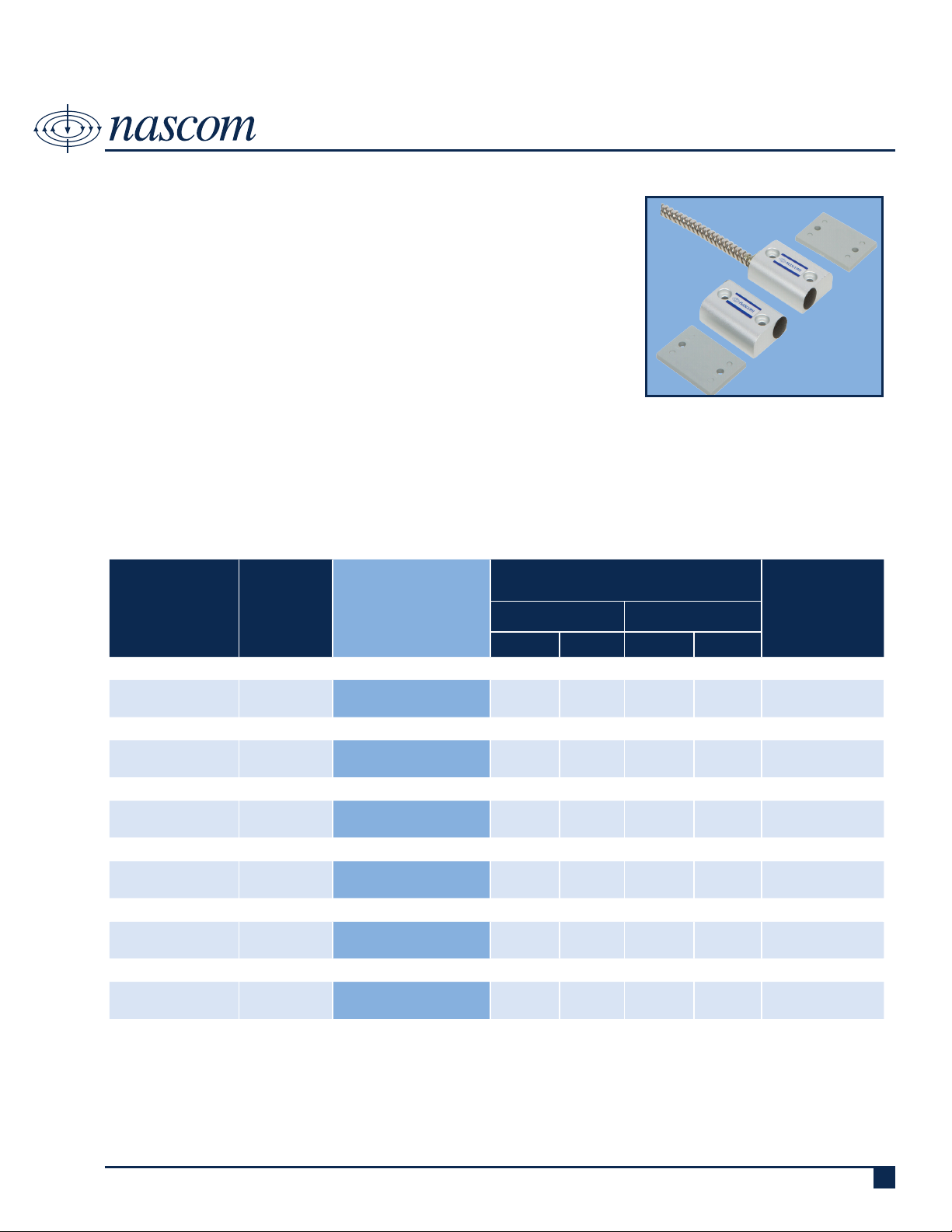
N505AS
SHORTY MITE MAN DOOR SET
DESCRIPTION
Nascom’s N505AS is a short, 2” block switch, designed for man doors. It
combines the installers’ choice of contact conguration with an N35 NdFeB
magnet for maximum gap performance.
The closed loop version of the N505AS prevents false alarms caused by
warping or shifting of doors, and features our unique NO DEAD SPOT™
technology.
FEATURES
• NO DEAD SPOT™ TECHNOLOGY • 24” ARMORED CABLE LEAD PROTECTION
• EXTRA WIDE GAP - N35 NdFeB RARE EARTH MAGNET • 36” 22AWG WIRE LEADS
• LISTED TO UL634 STANDARD • EXTRUDED ANODIZED (TYPE II) ALUMINUM
ORDERING INFORMATION
CONTACT RATING
PART
NUMBER
COLOR
OPERATE GAP
(in INCHES)
(Max DC/Peak AC Resistive)
SWITCHING CARRY
V I V I
CLOSED LOOP, NORMALLY OPEN, 1FA, SWITCH/MAGNET SET:
N505AS/ST SILVER 1.25 to 2.125 200 VDC 0.5 Amps 10vA 1.5 Amps 150 mOhms
DUAL CLOSED LOOP, NORMALLY OPEN, 1FA, SWITCH/MAGNET SET:
N505AS/ST2CR SILVER 1.25 to 2.125 200 VDC 0.5 Amps 10vA 0.5 Amps 150 mOhms
OPEN LOOP, NORMALLY CLOSED, 1FB, SWITCH/MAGNET SET:
N505AS/STFB SILVER 0.875 to 1.875 30 VDC 0.2 Amps 3vA 0.5 Amps 100 mOhms
SINGLE POLE DOUBLE THROW, SWITCH/MAGNET SET:
N505AS/STSD SILVER 0.875 to 1.875 30 VDC 0.2 Amps 3vA 0.5 Amps 100 mOhms
DOUBLE POLE DOUBLE THROW, SWITCH/MAGNET SET:
N505AS/STDD SILVER
HIGH SECURITY, NORMALLY OPEN, 1FA, SWITCH/MAGNET SET:
N505AS/STHS SILVER 0.1875 to 0.50 300 VDC
0.875 to 1.875 30 VDC 0.2 Amps 3vA 0.5 Amps 100 mOhms
0.25
Amps
10vA
0.25
Amps
STATIC
CONTACT
RESISTANCE
(50mV, 100mA)
150 mOhms
initial
Royne Industries LLC dba NASCOM
|
P: 800.843.5530
|
F: 800.727.4041
|
www.nascominc.com
DWG No. 120613-01 Rev. 2
1
Page 2
1.125
28.58
1.625
41.28
1.125
28.58
.500
12.70
END VIEW
FRONT VIEW
1.625
41.28
1.125
28.58
.500
12.70
1.125
28.58
FRONT VIEW
1.625
41.28
1.125
28.58
.125
3.18
1.125
28.58
FRONT VIEW
END VIEW
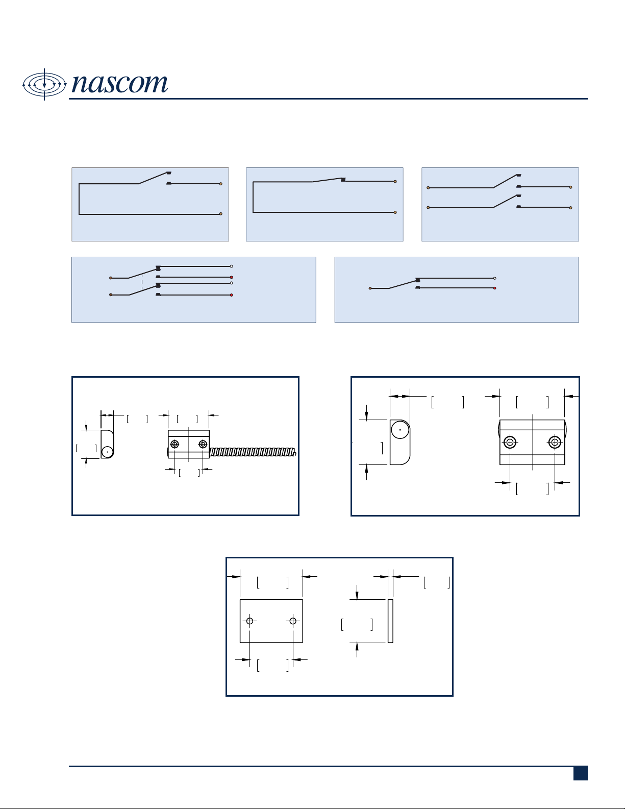
WIRING SCHEMATIC
N505AS
SHORTY MITE MAN DOOR SET
SWITCH
CONTACT
CLOSED LOOP,
NORMALLY OPEN CONTACT
COMMON
(BROWN)
COMMON
(BROWN)
DPDT, DOUBLE POLE DOUBLE THROW SPDT, SINGLE POLE DOUBLE THROW
OPEN LOOP,
NORMALLY CLOSED CONTACT
NC, OPEN LOOP (WHITE)
NO, CLOSED LOOP (RED)
NC, OPEN LOOP (WHITE)
NC, OPEN LOOP (WHITE)
SWITCH
CONTACT
COMMON
(BROWN)
DUAL CLOSED LOOP,
NORMALLY OPEN CONTACTS
DIMENSIONS - IN [mm]
NC, OPEN LOOP (WHITE)
NO, CLOSED LOOP (RED)
SWITCH
Royne Industries LLC dba NASCOM
MAGNET
SPACER
DWG No. 1200613-01 Rev. 2
|
P: 800.843.5530
|
F: 800.727.4041
|
www.nascominc.com
2
Page 3
N505AS
SHORTY MITE MAN DOOR SET
INSTALLATION INSTRUCTIONS
NOTE: For N505AS/STHS - red dots on switch and magnet must be aligned for correct operation.
• Position the switch on the door frame and the magnet on the door in desired location.
• Place one of the enclosed spacers under the switch and one spacer under the magnet and align the switch and magnet
housings as close as possible on the door with ¼” gap between the housings.
• Mark the mounting hole locations and drill mounting holes using a drill bit adequately sized for a #6 self-tapping screw.
• Place the spacer under the switch and attach to the door frame using two #6 Self-Tapping screws.
• Place the spacer under the Magnet and attach to the door using two #6 Self-Tapping screws.
• Connect an ohm meter to the switch leads and open and close the door to test switch for correct operation.
• Connect the switch leads to the alarm system.
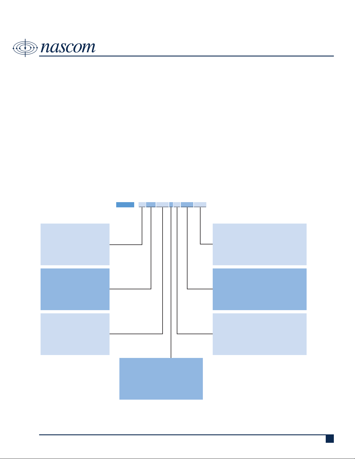
PART NUMBER SYSTEM
PRODUCT TYPE (1 or 2 digits):
• ST = SWITCH/MAGNET SET
• SW = SWITCH ONLY
• M = MAGNET ONLY
CIRCUIT (0, 2 or 3 digits):
• Blank = CLOSED LOOP
• 2CR = DUAL CLOSED LOOP
• FB = OPEN LOOP
• SD = SPDT
• DD = DPDT
• HS = HIGH SECURITY
LEAD LENGTH (zero, 3 or 4 digits):
• Blank - 24 Inches
• All other lengths specied in
Inches with 3 digits (e.g. 036 =
36 Inches)
* lead length is armored cable length-
wire length is 12 inches greater
than armored cable length
N505AS
WIRE TYPE (0 or 1 digit):
XX XXX/ XXXX X XX XXXX XXXX
• Blank = UL1061 | 22AWG | 7/30
• J = 2-conductor PVC Jacketed NEC Type
CL2 and CM
END OF LINE RESISTOR (zero to 4 digits):
• Blank = Resistor in series with the switch
• P = Resistor in parallel with the switch
• SP = Resistor 1 in series to the switch; resistor
2 in parallel to the switch
BUILT-IN END OF LINE RESISTOR VALUE (zero to 4
digits):
• Blank = No built-in end of line resistor
• All other resistor values are specied (e.g. 1K
= 1,000 Ω)
LEAD WIRE COLOR (zero to 2 digits):
• Blank = Switch Color except:
» resistor contacts standard is red wire
» all 2 conductor jacketed wire is grey
• BL = Blue leads
• OL = Orange leads
Royne Industries LLC dba NASCOM
|
P: 800.843.5530
|
F: 800.727.4041
|
www.nascominc.com
DWG No. 1200613-01 Rev. 2
3
 Loading...