

Page 1
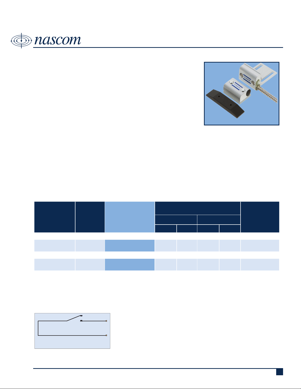
N505ASCD
SHORTY MITE CURTAIN DOOR SET
DESCRIPTION
Nascom’s N505ASCD is a short, 2” block switch with an L bracket, designed
for rollup or curtain doors. It combines the installers’ choice of contact con-
guration with an N35 NdFeB magnet for maximum gap performance.
The N505ASCD prevents false alarms caused by warping or shifting of doors,
and features our unique NO DEAD SPOT™ technology.
FEATURES
• NO DEAD SPOT™ TECHNOLOGY • 24” ARMORED CABLE LEAD PROTECTION
• EXTRA WIDE GAP - N35 NdFeB RARE EARTH MAGNET • 36” 22AWG WIRE LEADS
• PROTECTIVE WEAR PAD • EXTRUDED ANODIZED (TYPE II) ALUMINUM
• LISTED TO UL634 STANDARD
ORDERING INFORMATION
CONTACT RATING
PART
NUMBER
COLOR
OPERATE GAP
(in INCHES)
(Max DC/Peak AC Resistive)
SWITCHING CARRY
V I V I
CLOSED LOOP, NORMALLY OPEN, 1FA, SWITCH/MAGNET SET:
N505ASCD/ST SILVER 1.50 to 2.50 200 VDC 0.5 Amps 10vA 1.5 Amps 150 mOhms
DUAL CLOSED LOOP, NORMALLY OPEN, 1FA, SWITCH/MAGNET SET:
N505ASCD/ST2CR SILVER 1.50 to 2.50 200 VDC 0.5 Amps 10vA 0.5 Amps 150 mOhms
STATIC
CONTACT
RESISTANCE
(50mV, 100mA)
WIRING SCHEMATIC
SWITCH
CONTACT
CLOSED LOOP,
NORMALLY OPEN CONTACT
Royne Industries LLC dba NASCOM
|
P: 800.843.5530
|
F: 800.727.4041
|
www.nascominc.com
DWG No. 140207-01 Rev.
107
Page 2
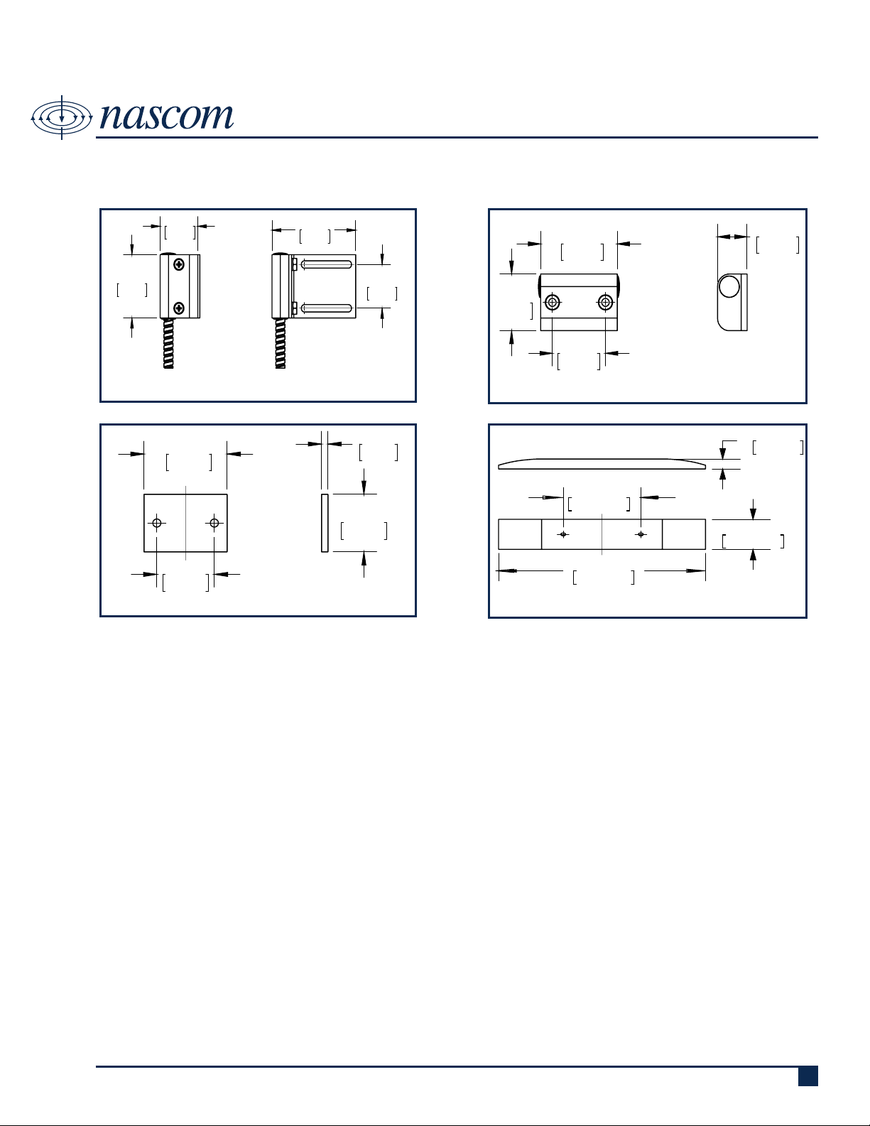
1.125
28.58
1.625
41.28
2.500
63.50
1.125
28.58
END VIEW
FRONT VIEW
1.625
41.28
1.125
28.58
1.125
28.58
.625
15.88
FRONT VIEW
END VIEW
DIMENSIONS - IN [mm]
1.625
41.28
1.125
28.58
.125
3.18
1.125
28.58
FRONT VIEW
END VIEW
1.125
28.58
3.000
76.20
.750
19.05
.250
6.35
FRONT VIEW
N505ASCD
SHORTY MITE CURTAIN DOOR SET
INSTALLATION INSTRUCTIONS
SWITCH
SPACER
• Lower the door to closed position. Make sure there are no obstructions to prevent complete closure of door.
• Position magnet at the desired height on door with the end of magnet housing aligned with inside edge of the door track.
Mark the position of magnet.
• Clean the area on door where magnet is to be mounted with alcohol.
• Remove the liner from the mounting tape on rear surface of magnet. Position the magnet where previously marked and
press the magnet onto door.
• Align the switch bracket assembly on the track with the magnet on door. The top edge of the magnet should align with
the midpoint on the switch housing. Make sure the back of switch housing is seated against the edge of the track.
• Using the slots in the bracket as a guide, drill two 5/32” holes in the track as close to the switch as possible.
• Position the wear pad on the inside of the track and align the holes in the wear pad with the holes you just drilled.
• Insert two #6X 5/8” screws thru the slots in the bracket and thru the holes drilled in track and into the holes in the wear
pad. Tighten screws carefully until assembly is snug on the track. Do not over tighten the screws.
• Use two #6X3/4” screws to mount the magnet if desired.
• Open the door to its fully open position to make sure the magnet will clear the door stop at the top of the door and to
make sure the Angle plate at the bottom of the door will clear the switch assembly. It may be necessary to notch the
angle plate at the bottom of the door to allow clearance for the door to move freely past the switch assembly.
• Connect the switch leads to an ohm meter and open and close the door to test switch for correct operation.
• Connect the switch leads to the alarm system.
Royne Industries LLC dba NASCOM
|
P: 800.843.5530
|
F: 800.727.4041
MAGNET
WEAR PAD
|
www.nascominc.com
DWG No. 140207-01 Rev. 1
108
Page 3

PART NUMBER SYSTEM
N505ASCD
SHORTY MITE CURTAIN DOOR SET
CIRCUIT (0, 2 or 3 digits):
• Blank = CLOSED LOOP
• 2CR = DUAL CLOSED LOOP
LEAD LENGTH (zero, 3 or 4 digits):
• Blank - 24 Inches
• All other lengths specied in
Inches with 3 digits (e.g. 036 =
36 Inches)
* lead length is armored cable length-
wire length is 12 inches greater
than armored cable length
WIRE TYPE (0 or 1 digit):
• Blank = UL1061 | 22AWG | 7/30
• J = 2-conductor PVC Jacketed
NEC Type CL2 and CM
N505ASCD
ST XXX/ XXXX X XX XXXXXXXX
END OF LINE RESISTOR (zero to 4 digits):
• Blank = Resistor in series with the switch
• P = Resistor in parallel with the switch
• SP = Resistor 1 in series to the switch; resistor
2 in parallel to the switch
BUILT-IN END OF LINE RESISTOR VALUE (zero to 4
digits):
• Blank = No built-in end of line resistor
• All other resistor values are specied (e.g. 1K
= 1,000 Ω)
LEAD WIRE COLOR (zero to 2 digits):
• Blank = Switch Color except:
» resistor contacts standard is red wire
» all 2 conductor jacketed wire is grey
• BL = Blue leads
• OL = Orange leads
Royne Industries LLC dba NASCOM
|
P: 800.843.5530
|
F: 800.727.4041
|
www.nascominc.com
DWG No. 140207-01 Rev. 1
109
 Loading...