

Page 1
INSTALLER: LEAVE THIS MANUAL WITH THE APPLIANCE.
CONSUMER: RETAIN THIS MANUAL FOR FUTURE REFERENCE.
NEVER LEAVE CHILDREN OR OTHER AT RISK INDIVIDUALS ALONE WITH THE APPLIANCE.
INSTALLATION AND
OPERATING INSTRUCTIONS
CERTIFIED UNDER AMERICAN NATIONAL STANDARDS: ANSI Z21.11.2 FOR UNVENTED ROOM HEATERS.
WHVF24N
NATURAL GAS
EN
CERTIFIED FOR CANADA AND UNITED STATES USING ANSI/CSA METHODS.
CERTIFIED FOR UNITED STATES USING ANSI METHODS.
SAFETY INFORMATION
!
WARNING
If the information in these instructions are
not followed exactly, a fi re or explosion
may result causing property damage,
personal injury or loss of life.
- Do not store or use gasoline or other fl ammable
vapors and liquids in the vicinity of this or any
other appliance.
- WHAT TO DO IF YOU SMELL GAS:
• Do not try to light any appliance.
• Do not touch any electrical switch; do
not use any phone in your building.
• Immediately call your gas supplier from
a neighbour’s phone. Follow the gas
supplier’s instructions.
• If you cannot reach your gas supplier,
call the fi re department.
- Installation and service must be performed by a
qualifi ed installer, service agency or the supplier.
- This is an unvented gas-fi red heater that
uses air (oxygen) from the room in which it is
installed. Provisions for adequate combustion
and ventilation air must be provided. Refer to
section “ COMBUSTION AND VENTILATION AIR
PROVISIONS”.
This appliance may be installed in an aftermarket,
permanently located, manufactured (mobile)
home, where not prohibited by local codes.
This appliance is only for use with the type of gas
indicated on the rating plate. This appliance is not
convertible for use with other gases.
WHVF24P
PROPANE
!
WARNING
HOT GLASS WILL CAUSE
BURNS.
DO NOT TOUCH GLASS UNTIL
COOLED.
NEVER ALLOW CHILDREN TO
TOUCH GLASS.
$10.00
Wolf Steel Ltd., 24 Napoleon Rd., Barrie, ON, L4M 0G8 Canada /
103 Miller Drive, Crittenden, Kentucky, USA, 41030
Phone (705)721-1212 • Fax (705)722-6031 • www.napoleonfi replaces.com • ask@napoleonproducts.com
1.43
W415-1158 / A / 11.19.13
Page 2

2
TABLE OF CONTENTS
EN
1.0 INSTALLATION OVERVIEW 3
2.0 INTRODUCTION 4
2.1 DIMENSIONS 5
2.2 GENERAL INSTRUCTIONS 5
2.3 GENERAL INFORMATION 6
2.4 RATING PLATE INFORMATION 7
3.0 INSTALLATION 8
3.1 COMBUSTION AND VENTILATION AIR PROVISIONS 8
3.2 DETERMINING CONFINED OR UNCONFINED SPACE 8
3.3 GAS INSTALLATION 10
3.4 MOBILE HOME 10
3.5 MOUNTING THE APPLIANCE 11
3.6 MINIMUM CLEARANCE TO COMBUSTIBLES 12
4.0 FINISHING 13
4.1 SURROUND INSTALLATION / REMOVAL 13
4.2 DOOR REMOVAL / INSTALLATION 13
4.3 GLASS MEDIA 14
5.0 IGNITION SYSTEM DIAGRAM 15
6.0 OPERATION 16
6.1 LIGHTING AND OPERATING INSTRUCTIONS 16
7.0 ADJUSTMENTS 17
7.1 VENTURI ADJUSTMENT 17
7.2 FLAME CHARACTERISTICS 17
8.0 MAINTENANCE 18
8.1 ANNUAL MAINTENANCE 18
8.2 CARE OF GLASS 19
8.3 CARE OF PLATED PARTS 19
8.4 DOOR GLASS REPLACEMENT 19
9.0 REPLACEMENTS 20
10.0 TROUBLESHOOTING 21
11.0 WARRANTY 22
12.0 SERVICE HISTORY 23
NOTE: Changes, other than editorial, are denoted by a line in the margin.
W415-1158 / A / 11.19.13
Page 3
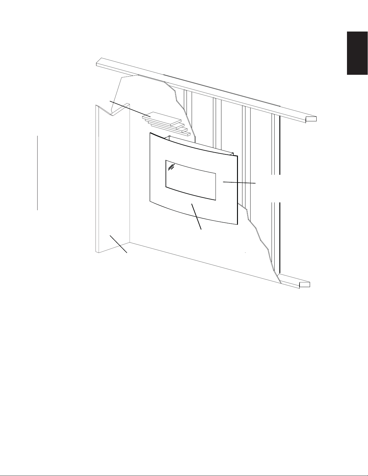
1.0 INSTALLATION OVERVIEW
Mantel, see
“MINIMUM
CLEARANCES TO
COMBUSTIBLES”
section.
Side Wall
3
EN
Rating plate, see “RATING
PLATE INFORMATION”
section.
Side Wall, see
“MINIMUM
CLEARANCES TO
COMBUSTIBLES”
section.
Surround, see
“FINISHING” section.
W415-1158 / A / 11.19.13
Page 4

4
2.0 INTRODUCTION
EN
(
!
WARNING
• THIS APPLIANCE IS HOT WHEN OPERATED AND CAN CAUSE SEVERE BURNS IF CONTACTED.
• ANY CHANGES TO THIS APPLIANCE OR ITS CONTROLS CAN BE DANGEROUS AND IS PROHIBITED.
• Under no circumstances should this appliance be modifi ed.
• Do not operate appliance before reading and understanding operating instructions. Failure to operate
appliance according to operating instructions could cause fi re or injury.
• Risk of burns. The appliance should be turned off and cooled before servicing.
• Do not install damaged, incomplete or substitute components.
• Risk of cuts and abrasions. Wear protective gloves and safety glasses during installation. Sheet metal edges
may be sharp.
• Provide adequate ventilation and combustion air. Provide adequate accessibility clearance for servicing and
operating the appliance. Never obstruct the front opening of the appliance.
• If the appliance shuts off, do not re-light until you provide fresh air. If appliance keeps shutting off, have it
serviced. Keep burner and control compartment clean.
• Do not burn wood or other materials in this appliance.
• Children and adults should be alerted to the hazards of high surface temperature and should stay away to
avoid burns or clothing ignition.
• Young children should be carefully supervised when they are in the same room as the appliance. Toddlers,
young children and others may be susceptible to accidental contact burns. A physical barrier is recommended
if there are at risk individuals in the house. To restrict access to an appliance, install an adjustable safety gate
to keep toddlers, young children and other at risk individuals out of the room and away from hot surfaces.
• Due to high temperatures, the appliance should be located out of traffi c and away from furniture and
draperies.
• Ensure you have incorporated adequate safety measures to protect infants/toddlers from touching hot
surfaces.
• Clothing or other fl ammable material should not be placed on or near the appliance.
• Check with your local hearth specialty dealer for safety screens and hearth guards to protect children from
hot surfaces. These screens and guards must be fastened to the fl oor.
• Any safety screen or guard removed for servicing must be replaced prior to operating the appliance.
• It is imperative that the control compartments, burners and circulating blower and its passageway in the
appliance are kept clean. The appliance should be inspected before use and at least annually by a qualifi ed
service person. More frequent cleaning may be required due to excessive lint from carpeting, bedding
material, etc. The appliance area must be kept clear and free from combustible materials, gasoline and other
fl ammable vapours and liquids.
• Furniture or other objects must be kept a minimum of 4 feet (1.2m) away from the front of the appliance.
• Do not use this appliance if any part has been under water. Immediately call a qualifi ed service technician
to inspect the appliance and to replace any part of the control system and any gas control which has been
under water.
• Do not allow fans to blow directly into the appliance. Avoid any drafts that alter burner fl ame patterns.
• Do not use a blower insert, heat exchanger insert or other accessory not approved for use with this appliance.
• Carbon or soot should not occur in a vent free appliance as it can distribute into the living area of your home.
If you notice any signs of carbon or soot, immediately turn off your appliance and arrange to have it serviced
by a qualifi ed technician before operating it again.
• Keep the packaging material out of reach of children and dispose of the material in a safe manner. As with all
plastic bags, these are not toys and should be kept away from children and infants.
• As with any combustion appliance, we recommend having your appliance regularly inspected and serviced as
well as having a Carbon Monoxide Detector installed in the same area to defend you and your family against
Carbon Monoxide.
• If equipped, the screen must be in place (closed) when the appliance is in operation.
• Ensure clearances to combustibles are maintained when building a mantel or shelves above the appliance.
Elevated temperatures on the wall or in the air above the appliance can cause melting, discolouration or
damage to decorations, a T.V. or other electronic components.
3.4C
W415-1158 / A / 11.19.13
Page 5
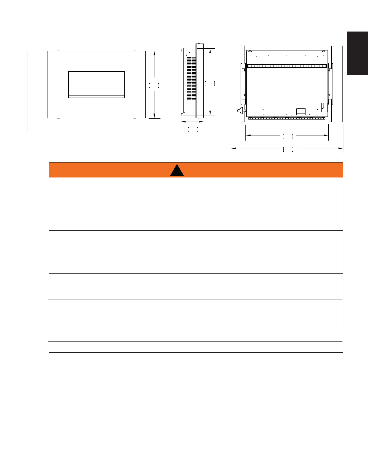
2.1 DIMENSIONS
5
EN
2.2 GENERAL INSTRUCTIONS
* CARBON MONOXIDE POISONING MAY LEAD TO DEATH
EARLY SIGNS OF CARBON MONOXIDE POISONING RESEMBLE THE FLU, WITH HEADACHE,
DIZZINESS AND/OR NAUSEA. IF YOU HAVE THESE SIGNS, THE HEATER MAY NOT BE WORKING
PROPERLY. GET FRESH AIR AT ONCE! HAVE HEATER SERVICED.
SOME PEOPLE---PREGNANT WOMEN, PERSONS WITH HEART OR LUNG DISEASE, ANEMIA, THOSE
UNDER THE INFLUENCE OF ALCOHOL, THOSE AT HIGH ALTITUDES--- ARE MORE AFFECTED BY
CARBON MONOXIDE THAN OTHERS.
FAILURE TO KEEP THE PRIMARY AIR OPENING(S) OF THE BURNER(S) CLEAN MAY RESULT IN
SOOTING AND PROPERTY DAMAGE.
22"
559mm
19 1/4"
487mm
6 7/8"
175mm
!
WARNING
23 3/4"
605mm
32 3/8"
822mm
THE APPLIANCE IS ONLY FOR USE WITH THE TYPE OF GAS INDICATED ON THE RATING PLATE.
THIS APPLIANCE IS NOT CONVERTIBLE FOR USE WITH OTHER GASES. THIS APPLIANCE IS
INTENDED FOR SUPPLEMENTAL HEATING.
OBJECTS PLACED IN FRONT OF THE HEATER SHOULD BE KEPT A MINIMUM OF 48” (1219.2mm)
AWAY FROM THE FRONT FACE OF THE APPLIANCE. KEEP APPLIANCE AREA CLEAR AND FREE
FROM COMBUSIBLE MATERIALS, GASOLINE AND OTHER FLAMMABLE VAPORS AND LIQUIDS.
USE ONLY WOLF STEEL APPROVED OPTIONAL ACCESSORIES AND REPLACEMENT PARTS WITH
THIS APPLIANCE. USING NON-LISTED ACCESSORIES AND REPLACEMENT PARTS (BLOWERS,
LOUVRES, TRIMS, GAS COMPONENTS, VENT COMPONENTS, ETC.) COULD RESULT IN A SAFETY
HAZARD AND WILL VOID THE LIMITED LIFETIME WARRANTY.
THIS APPLIANCE MUST NOT BE INSTALLED IN A BATHROOM.
DO NOT OPERATE WITHOUT CERAMIC CATALYST IN PLACE.
This gas appliance should be installed and serviced by a qualifi ed installer to conform with local codes.
Installation practices vary from region to region and it is important to know the specifi cs that apply to your
area, for example: in Massachusetts State:
• The appliance off valve must be a “T” handle gas cock.
• The fl exible connector must not be longer than 36” (914.4mm).
• The appliance is not approved for installation in a bathroom unless the appliance is a direct vent sealed
combustion product.
• A carbon monoxide detector is required in all rooms containing gas fi red appliances.
• WARNING: This product must be installed by a licensed plumber or gas fi tter when installed within the
commonwealth of Massachusetts.
• Un-vented room appliance shall be installed in accordance with 527 CMR 30.00 and 248 CMR 3.00
through 7.00.
W415-1158 / A / 11.19.13
Page 6
g
EN
6
• Sellers of un-vented propane or natural gas-fi red space / room appliances shall provide to each purchaser
a copy of 527 CMR 30.00 upon the sale of the appliance from http://www.napoleonfi replaces.com/
Webshare/installation_manuals/mass_requirements.pdf
In absence of local codes, install the appliance to the current National Fuel Gas Code, ANSI Z223.1
Installation Code which can be obtained from:
American National Standards Institute Inc. or National Fire Protection Association Inc.
1430 Broadway Batterymarch Park
New York, NY 10018 Quincy, MA 02269
The appliance and its individual shutoff valve must be disconnected from the gas supply piping system during
any pressure testing of that system at test pressures in excess of 1/2 psig (35mb). The appliance must be
isolated from the gas supply piping system by closing its individual manual shutoff valve during any pressure
testing of the gas supply piping system at test pressures equal to or
less than 1/2 psig (35mb). When installed with a blower the junction
box must be electrically connected and grounded in accordance with
local codes. In the absence of local codes, use the current ANSI /
NFPA 70 National Electric Code. In the case where the blower is
equipped with a power cord it must be connected into a properly
grounded receptacle. The grounding prong must not be removed
from the cord plug.
As long as the required clearance to combustibles is maintained,
the most desirable and benefi cial location for the appliance is in the center of a building, thereby allowing the
most effi cient use of the heat created. The location of windows, doors and the traffi c fl ow in the room where
the appliance is to be located should be considered.
* Air shortage caused by an inadequate air supply, improper log positions, the addition of foreign or
unapproved materials or the failure to properly maintain the appliance, may result in incomplete combustion of
the fuel. Incomplete combustion results in soot being deposited inside the fi rebox as well as surfaces outside
the appliance. If any soot deposits are observed, shut off the appliance immediately and arrange for it to
be serviced by a qualifi ed technician. Incomplete combustion can also generate increased levels of carbon
monoxide (CO).
2.3 GENERAL INFORMATION
www.ncertied.org
We suggest that our gas
hearth products be installed
and serviced by professionals
who are certied in the U.S.
by the National Fireplace
®
Institute
Specialists
4.13
(NFI) as NFI Gas
FOR YOUR SATISFACTION, THIS APPLIANCE HAS BEEN TEST-FIRED TO ASSURE ITS OPERATION
AND QUALITY!
RATES AND EFFICIENCIES
NATURAL GAS PROPANE GAS
Altitude 0-2000* 0-2000*
Maximum Input 9,000 BTU/hr (2.6kw/hr) 9,000 BTU/hr (2.6kw/hr)
Effi ciency 99.9% 99.9%
Minimum Inlet Gas Supply Pressure 4.5” Water Column (11.2mb) 11” Water Column (27.3mb)
Maximum Inlet Gas Supply Pressure 7” Water Column (17.4mb) 13” Water Column (32.8mb)
Manifold Pressure Under Flow Conditions 3.5” Water Column (8.7mb) 10” Water Column (25mb)
* When the appliance is installed at elevations above 2,000ft (609.6m), and in the absence of specifi c recom-
mendations from the local authority having jurisdiction, the certifi ed high altitude input rating shall be reduced
at the rate of 4% for each additional 1,000ft (304.8m).
This appliance is suitable for mobile home installation. The natural gas model can only be installed in a mobile
home that is permanently positioned on its site and fueled with natural gas. This appliance may be installed in
an aftermarket permanently located, manufactured (mobile) home, where not prohibited by local codes.
This appliance is only for use with the type of gas indicated on the rating plate. This appliance is not
convertible for use with other gases.
W415-1158 / A / 11.19.13
Page 7
The appliance is equipped with two catalytic tiles which are designed to fi lter out harmful gases and limit
carbon monoxide output. It is likely that with the appliance in operation, the catalytic tiles will actually scrub
the carbone monoxide normally found in the room and reduce it to a lower level. The tiles must not be altered
or removed. Do not operate the appliances when using products such as paint, paint thinner, adhesives, etc.
These products will permanently affect the catalytic tiles’ ability to scrub the air.
Expansion / contraction noises during heating up and cooling down cycles are normal and are to be expected.
2.4 RATING PLATE INFORMATION
For rating plate location, see “INSTALLATION OVERVIEW”
section.
This illustration is for reference only. Refer to the rating
plate on the appliance for accurate information.
NOTE: The rating plate must remain with the appliance
at all times. It must not be removed.
CERTIFIED UNDER: ANSI Z21.11A-2010 UNVENTED ROOM HEATER
THIS APPLIANCE SHALL NOT BE INSTALLED IN BATHROOM, AND IS
INTENDED FOR SUPPLEMENTAL HEATING. THIS APPLIANCE MAY BE
INSTALLED IN AN AFTERMARKET, PERMANENTLY LOCATED,
MANUFACTURED (MOBILE) HOME, WHERE NOT PROHIBITED BY
LOCAL CODES. THIS APPLIANCE IS ONLY FOR
USE WITH THE TYPE OF GAS INDICATED ON
THE RATING PLATE. THIS APPLIANCE IS NOT
FIELD CONVERTIBLE FOR USE WITH OTHER
GASES. THIS IS A GAS-FIRED UNVENTED
ROOM HEATER THAT REQUIRES ADEQUATE
COMBUSTION AND VENTILATION AIR.
CERTIFIED FOR / CERTIFIEE
POUR CANADA / USA
REFERENCE # 161746
7
EN
WHVF24 CWHVF24N
*0-2000FT ALTITUDE *0-2000FT
9,000 BTU/HR INPUT 9,000BTU/HR
BQ902C01 CONTROL BQ902C01
BENAN 20310 (NG) PILOT
*ABOVE 2,000FT, CONSULT LOCAL AUTHORITY HAVING JURISDICTION.
MANIFOLD PRESSURE: 3.5”
WATER COLUMN (NG)
MIN. SUPPLY PRESSURE: 4.5”
WATER COLUMN (NG)
MAX. SUPPLY PRESSURE: 7”
WATER COLUMN (NG)
BENAN 20310 (LP)
MANIFOLD PRESSURE: 10”
WATER COLUMN (LP)
MIN. SUPPLY PRESSURE: 11”
WATER COLUMN (LP)
MAX. SUPPLY PRESSURE: 13”
WATER COLUMN (LP)
WHVF24CWHVF24P
LEDOM ENAPORP LEDOM SAG LARUTAN
NOT FOR USE WITH SOLID FUEL
WARNING: DO NOT ADD ANY MATERIAL TO THE APPLIANCE,
WHICH WILL COME IN CONTACT WITH THE FLAME. DO NOT USE
ACCESSORIES NOT APPROVED FOR USE WITH THIS APPLIANCE.
APPLY LOOSE MATERIAL PER INSTRUCTIONS MANUAL. DO NOT
APPLY EXTRA MATERIAL OR MATERIAL NOT SUPPLIED WITH THE
APPLIANCE. IMPROPER INSTALLATION, ADJUSTMENT, ALTERNATION,
SERVICE OR MAINTENANCE CAN CAUSE PROPERTY DAMAGE,
PERSONAL INJURY OR LOSS OF LIFE. REFER TO THE OWNER’S
INFORMATION MANUAL PROVIDED WITH THIS APPLIANCE.
INSTALLATION AND SERVICE MUST BE PERFORMED BY A QUALIFIED
INSTALLER, SERVICE AGENCY OR THE GAS SUPPLIER.
MINIMUM CLEARANCE TO COMBUSTIBLE MATERIAL
(FROM APPLIANCE):
MANTEL 20”
FLOOR 10”
SIDES 7”
WOLF STEEL LTD.
24 NAPOLEON ROAD, BARRIE, ON, L4M 0G8 CANADA
SERIAL NUMBER
WHVF24
W415-1158 / A / 11.19.13
Page 8
A
A
8
3.0 INSTALLATION
EN
3.1 COMBUSTION AND VENTILATION AIR PROVISIONS
This appliance shall not be installed in a confi ned space or unusually tight construction unless provisions are
provided for adequate combustion and ventilation air.
The National Fuel Gas Code, ANSI Z223.1 / NFPA 54 defi nes a confi ned space as a space whose volume is
less than 50 cubic feet per 1,000 Btu per hour (4.8 m3 per kw) of the aggregate input rating of all appliances
installed in that space and an unconfi ned space as a space whose volume is not less than 50 cubic feet per
1,000 Btu per hour (4.8 m3 per kw) of the aggregate input rating of all appliances installed in that space.
Rooms communicating directly with the space in which the appliances are installed, through openings not
furnished with doors are considered a part of the unconfi ned space.
17.1A
The WHVF24 is rated at 9,000 BTUs per hour for natural gas and propane and therefore requires a minimum
unconfi ned space of 450 cubic feet.
3.2 DETERMINING CONFINED OR UNCONFINED SPACE
To determine the volume of the room where the appliance is to be installed, multiply the width x the length x
the ceiling height of that room measured in feet. If any adjoining rooms are connected by grilles or openings
such as kitchen pass-throughs, etc., the volume of those rooms may be added to the total.
Multiply the room volume by 1000 and divide this amount by 50 to determine the maximum BTU/hr that the
space can support with adequate combustion and ventilation air.
dd the Btu/hr of all fuel burning appliances located within the space such as gas furnace, gas water
appliance, etc. Do not include direct vent gas appliances which draw their input and output air from and to the
outdoors.
!
WARNING
IF THE AREA IN WHICH THE APPLIANCE MAY BE OPERA TED IS SMALLER THAN THAT DEFINED AS
AN UNCONFINED SP ACE OR IF THE BUILDING IS OF UNUSUALLY TIGHT CONSTRUCTION, PROVIDE
ADEQUA TE COMBUSTION AND VENTILATION AIR BY ONE OF THE METHODS DESCRIBED IN THE
NA TIONAL FUEL GAS CODE ANSI Z223.1/ NFPA 54 , AIR FOR COMBUSTION AND VENTILATION, OR THE
APPLICABLE LOCAL CODE.
IF THE AREA IN WHICH THE APPLIANCE MAY BE OPERA TED DOES NOT MEET THE REQUIRED VOLUME
FOR INDOOR COMBUSTION AIR, COMBUSTION AND VENTILATION AIR SHALL BE PROVIDED BY ONE
OF THE METHODS DESCRIBED IN THE ANSI Z223.1 / NFPA 54, THE INTERNATIONAL FUEL GAS CODE,
OR APPLICABLE LOCAL CODES.
Unusually tight construction is defi ned as construction where:
A) Walls and ceilings exposed to the outside atmosphere have a continuous water vapour retarder with a
rating of 1 perm (6 x 10-11 kg per pa-sec-m2) or less with openings gasketed or sealed, and
B) Weather stripping has been added on openable windows and doors, and
C) Caulking or sealants are applied to areas such as joints around window and door frames, between sole
plates and fl oors, between wall-ceiling joints, between wall panels, at penetrations for plumbing, electrical,
and gas lines, and at other openings.
n unvented room appliance is recommended for use as a secondary heat source rather than as a primary
source. Gas combustion produces water vapour which could occur at the rate of approximately one ounce of
water for every 1,000 BTU/hr of gas input. During the cold weather season, indoor humidity levels tend to be
low. Consequently, this water vapour can enhance the living space. However if a problem should occur:
A) Ensure suffi cient combustion and circulation air
B) Use a dehumidifi er
C) Do not use the unvented room appliance as a primary heat source
Without suffi cient fresh air for proper operation, poor fuel combustion can result. Carbon Monoxide is a result
of poor combustion.
If additional fresh air is required, use one of the methods described in the National Fuel Gas Code, ANSI
Z223.1 / NFPA54 or the applicable local code.
Continued on next page
W415-1158 / A / 11.19.13
Page 9

Room Volume = Length x Width x Height
LENGTH
HEIGHT
ROOM 2
ROOM 1
WIDTH
Max BTU/hr = Room Volume x 1000 / 50
If for example:
The length of the rooms is 5 feet (1.5m),
The width of Room 1 is 10 feet (3.1m),
The width of Room 2 is 15 feet (4.6m),
The height of the rooms is 8 feet (2.4m).
The volume of Room 1: 5x10x8 = 400 cubic feet
(1.5 x 3.1 x 2.4 = 1 1.16 cubic meters)
The volume of Room 2: 5x15x8 = 600 cubic feet
(1.5 x 4.6 x 2.4 = 16.56 cubic meters)
19.1C
EXAMPLE 1:
In this example, because there is no door to the adjoining room, the volume of the adjoining room may be
added to the volume of the room with the heater to get a total unconfi ned space.
9
EN
The total unconfi ned space: 400 ft3 (11.3m3)+ 600 ft3 (17m3) = 1000 cubic feet (28.3m3).
Maximum BTU/h: 1000x1000 = 20,000 BTU/h
50
19.2A
EXAMPLE 2:
If in this example a solid door separates Room 1 from Room 2, the volume of Room 2 could not be used. In
this case the maximum BTU/h would be:
Maximum BTU/h: 400x1000 = 8,000 BTU/h
50
19.3
This would be considered a confi ned space since it can not support the 9,000 BTU/h input of the appliance
and it would be necessary to provide adequate combustion and ventilation air to Room 1.
W415-1158 / A / 11.19.13
Page 10

10
3.3 GAS INSTALLATION
EN
!
WARNING
RISK OF FIRE, EXPLOSION OR ASPHYXIATION. ENSURE THERE ARE NO IGNITION SOURCES SUCH AS
SUPPORT GAS CONTROL WHEN ATTACHING GAS SUPPLY PIPE TO PREVENT DAMAGING GAS LINE.
ALWAYS LIGHT THE PILOT WHETHER FOR THE FIRST TIME OR IF THE GAS SUPPLY HAS RUN OUT
WITH THE GLASS DOOR OPENED OR REMOVED. PURGING OF THE GAS SUPPLY LINE SHOULD BE
PERFORMED BY A QUALIFIED SERVICE TECHNICIAN. ASSURE THAT A CONTINUOUS GAS FLOW IS AT
THE BURNER BEFORE CLOSING THE DOOR. ENSURE ADEQUATE VENTILATION. FOR GAS AND
ELECTRICAL LOCATIONS, SEE “DIMENSION” SECTION.
ALL GAS CONNECTIONS MUST BE CONTAINED WITHIN THE APPLIANCE WHEN COMPLETE.
HIGH PRESSURE WILL DAMAGE VALVE. DISCONNECT GAS SUPPLY PIPING BEFORE TESTING GAS
LINE AT TEST PRESSURES ABOVE 1/2 PSIG.
VALVE SETTINGS HAVE BEEN FACTORY SET, DO NOT CHANGE.
Installation and servicing to be done by a qualifi ed installer . Do not use open fl ame.
• Move the appliance into position and secure.
• If equipped with a fl ex connector the appliance is designed to accept a 1/2” (12.7mm) gas supply.
Without the connector it is designed to accept a 3/8” (9.5mm) gas supply. The appliance is equipped
with a manual shut off valve to turn off the gas supply to the appliance.
• Connect the gas supply in accordance to local codes. In the absence of local codes, install to the
current CAN/CSA-B149.1 Installation Code in Canada or to the current National Fuel Gas Code, ANSI
Z223.1 / NFPA 54 in the United States.
• When fl exing any gas line, support the gas valve so that the lines are not bent or kinked.
• Check for gas leaks by brushing on a soap and water solution.
SPARKS OR OPEN FLAMES.
30.1
3.4 MOBILE HOME
Suitable for mobile home installation where the mobile home has been permanently placed on its site.
This appliance may be installed in an aftermarket permanently located, manufactured (mobile) home, where
not prohibited by local codes.
For mobile home installations, the appliance must be fastened in place. It is recommended that the appliance
be secured in all installations. See “REPLACEMENTS” section for the levelling / securing kit specifi c to your
appliance.
29.2
W415-1158 / A / 11.19.13
Page 11

3.5 MOUNTING THE APPLIANCE
A. Level and affi x the paper template to the wall at desired location and height. See “MINIMUM
CLEARANCES TO COMBUSTIBLES” section for the minimum clearance requirement.
B. Using the paper template, mark the mounting screw locations.
C. Install the mounting bracket onto the wall using the two screws as shown in Figure 1. Make sure the
mounting bracket is level on the wall and the slots are facing upward. NOTE: The mounting screws
must go into a wall stud or proper anchors.
D. Mount the appliance onto the mounting bracket by placing the appliance into the slots until it is
secured in place, see Figure 2. NOTE: Ensure the appliance is resting securely in the slots.
E. Further secure the bottom of the appliance with the two screws, see Figure 3. NOTE: It is strongly
recommended that the appliance be screwed into the wall studs where possible. If the wall
studs cannot be used, ensure that the proper anchors (not supplied) are used to affi x the
appliance to the wall and the appliance is adequately secured.
FIG. 1
FIG. 2
11
EN
FIG. 3
W415-1158 / A / 11.19.13
Page 12

EN
12
3.6 MINIMUM CLEARANCE TO COMBUSTIBLES
Clearances are measured from the appliance.
MINIMUM CLEARANCES TO COMBUSTIBLES:
- 20” (508mm) to top
- 7” (177.8mm) to sides
- 10” (254mm) to bottom
- 36” (914.4mm) to rear
20" (508mm)
MIN.
20" (508mm)
MIN.
36"
(914.4mm)
MAX.
7"
(177.8mm)
MIN.
INSTALLATION
ALCOVE
TOP VIEW
7"
(177.8mm)
MIN.
10" (254mm)MIN.
36"
(914.4mm)
MAX.
ALCOVE
INSTALLATION
SIDE VIEW
10"
(254mm)
MIN.
TYPICAL
INSTALLATION
W415-1158 / A / 11.19.13
Page 13

4.0 FINISHING
13
!
WARNING
RISK OF FIRE!
NEVER OBSTRUCT THE FRONT OPENING OF THE APPLIANCE.
DO NOT STRIKE, SLAM OR SCRATCH GLASS. DO NOT OPERATE APPLIANCE WITH GLASS
REMOVED, CRACKED, BROKEN OR SCRATCHED.
4.1 SURROUND INSTALLATION / REMOVAL
A. Lift the surround and engage the hooks into the studs on the appliance, then let it slide down into
position.
WARNING:
Do not let glass go until
you ensure hooks have
engaged the studs. Handle
glass with care, if edge of
glass strikes a hard sur-
face, it will shatter.
EN
72.4
STUDS
4.2 DOOR REMOVAL / INSTALLATION
!
GLASS MAY BE HOT, DO NOT TOUCH GLASS UNTIL COOLED.
THE DOOR LATCHES ARE PART OF A SAFETY SYSTEM AND MUST BE PROPERLY ENGAGED. DO
NOT OPERATE THE APPLIANCE WITH LATCHES DISENGAGED.
FACING AND/OR FINISHING MATERIALS MUST NOT INTERFERE WITH AIR FLOW THROUGH AIR
OPENINGS, LOUVRES OPENINGS, OPERATION OF LOUVRES OR DOORS OR ACCESS FOR
SERVICE. OBSERVE ALL CLEARANCES WHEN APPLYING COMBUSTIBLE MATERIALS.
WARNING
BEFORE DOOR IS REMOVED TURN THE APPLIANCE OFF AND WAIT UNTIL APPLIANCE IS COOL TO
THE TOUCH. DOORS ARE HEAVY AND FRAGILE SO HANDLE WITH CARE.
75.1
W415-1158 / A / 11.19.13
Page 14

EN
14
A. Remove the surround, see “SURROUND INSTALLATION / REMOVAL” section.
B. Remove the two screws on the upper frame that secure the door.
Loosen the two screws on the lower frame. NOTE: These lower screws support thr door assembly
and should not be removed.
C. Lift the door up and off.
B
C
4.3 GLASS MEDIA
CLEAN THE GLASS MEDIA PRIOR TO INSTALLATION. BEFORE APPLYING THE CLEANED GLASS, ENSURE
DO NOT CHANGE OR SUBSTITUTE THE GLASS MEDIA MATERIAL PROVIDED WITH THIS APPLIANCE. IF
REPLACING, USE ONLY THE REPLACEMENT GLASS MEDIA AVAILABLE FROM YOUR AUTHORIZED
GLASS MEDIA OVER THE BURNER MUST NOT BE MORE THAN ONE LAYER HIGH. MORE THAN ONE LAYER
OVER THE BURNER WILL CAUSE FLAME LIFTING AND SOOTING PROBLEMS.
Evenly spread the glass media onto the media tray, covering the burner tube and tray.
Do not cover burner ports with glass media. Glass media over the burner ports may cause a “Puffi ng” sound.
To eliminate this sound, simply push the media away from the burner ports.
NOTE: The distribution of glass media over the burner ports will infl uence the fl ame height. When the
fl ames impinge on the glass, the glass may discolour slightly and the edges may soften.
CLEANING GLASS MEDIA
Glass media may have a fi ne oil residue that needs to be cleaned prior to installation. Clean the glass with mild
dish soap, drain, rinse thoroughly and dry before placing over the burner.
!
WARNING
THAT IT IS DRY.
DEALER / DISTRIBUTOR.
74.1B
W415-1158 / A / 11.19.13
Page 15
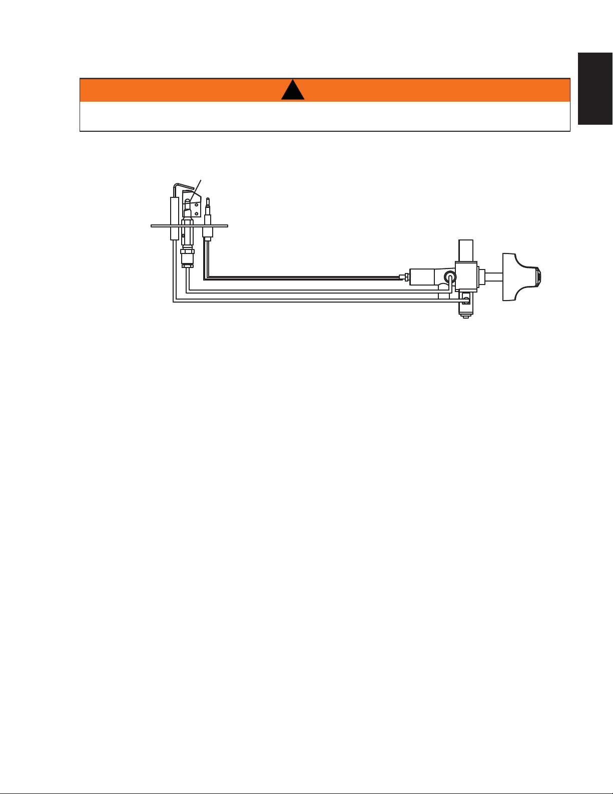
5.0 IGNITION SYSTEM DIAGRAM
15
!
WARNING
ENSURE ALL POWER IS TURNED OFF BEFORE HARD WIRING THIS APPLIANCE.
CONSULT A QUALIFIED ELECTRICIAN TO ENSURE CORRECT BRANCH CIRCUIT CONDUCTOR.
PILOT
ELECTRODE
THERMOCOUPLE
VALVE
EN
KNOB
W415-1158 / A / 11.19.13
Page 16

16
6.0 OPERATION
EN
When lit for the fi rst time, the appliance will emit a slight odour for a few hours. This is a normal temporary con-
dition caused by the “burn-in” of internal paints and lubricants used in the manufacturing process and will not
occur again. Simply open a window to suffi ciently ventilate the room. After extended periods of non-operation
such as following a vacation or a warm weather season, the appliance may emit a slight odour for a few hours.
This is caused by dust particles in the heat exchanger burning off. Open a window to suffi ciently ventilate the
room.
6.1 LIGHTING AND OPERATING INSTRUCTIONS
A. Locate the pilot adjustment knob on
the bottom right of appliance.
B. Push and turn the knob counter
clockwise to the “PILOT ON” position
and hold for a few seconds to ignite
the pilot.
C. Once the pilot is lit, slightly push the
knob and turn counter clockwise to
light the main burner.
D. To adjust the fl ame height, push the
knob and turn to desired height.
NOTE: When fi rst lighting the pilot, push
the knob and hold for 30 seconds to purge
the gas line. WARNING: Do not hold for
more than a minute.
FOR YOUR SAFETY READ BEFORE OPERATING
LIGHTING INSTRUCTIONS
1. STOP! READ ALL INFORMATION OF OPERATING AND LIGHTING
INSTRUCTIONS BEFORE PROCEEDING.
2. THIS FIREPLACE IS EQUIPPED WITH AN IGNITION DEVICE WHICH
AUTOMATICALLY LIGHTS THE PILOT. DO NOT TRY TO LIGHT THE PILOT BY
HAND.
3. TURN MANUAL SHUTOFF VALVE CLOCKWISE
4. WAIT FIVE (5) MINUTES TO CLEAR OUT ANY GAS. IF YOU
SMELL GAS INCLUDING NEAR THE FLOOR, STOP! FOLLOW
“B” OF THE OPERATING INSTRUCTIONS. IF YOU DON’T
SMELL GAS GO TO THE NEXT STEP.
5. TURN MANUAL SHUTOFF VALVE COUNTER-CLOCKWISE
TO ON.
6. TURN ON MAIN BURNER.
IF THE APPLIANCE WILL NOT OPERATE, FOLLOW THE INSTRUCTIONS “TO
TURN OFF GAS” AND CALL YOUR SERVICE TECHNICIAN OR GAS SUPPLIER.
TO OFF .
OPERATING INSTRUCTIONS
WARNING:
EXACTLY,
PROPERTY DAMAGE,
SEE INSTALLATION INSTRUCTIONS.
A. THIS FIREPLACE IS EQUIPPED WITH AN IGNITION DEVICE WHICH
AUTOMATICALLY LIGHTS THE PILOT. DO NOT TRY TO LIGHT BY HAND.
B. BEFORE OPERATING SMELL ALL AROUND THE FIREPLACE AREA FOR GAS
AND NEXT TO THE FLOOR BECAUSE SOME GAS IS HEAVIER THAN AIR AND
WILL SETTLE ON THE FLOOR.
WHAT TO DO IF YOU SMELL GAS:
TURN OFF ALL GAS TO THE FIREPLACE.
23(1:,1'2:6
'212T TRY TO LIGHT ANY APPLIANCE.
'212T TOUCH ANY ELECTRIC SWITCH; DO NOT USE ANY PHONE IN YOUR
BUILDING.
,00(',ATELY CALL YOUR GAS SUPPLIER FROM A NEIGHBOUR’S PHONE.
FOLLOW THE GAS SUPPLIER’S INSTRUCTIONS.
,) YOU CANNOT REACH YOUR GAS SUPPLIER, CALL THE FIRE DEPARTMENT.
C. DO NOT TRY TO REPAIR ANY PART OF THIS ASSEMBLY. CALL A QUALIFIED
SERVICE TECHNICIAN. FORCE OR ATTEMPTED REPAIR MAY RESULT IN A FIRE
OR EXPLOSION.
D. DO NOT USE THIS FIREPLACE IF ANY PART HAS BEEN UNDER WATER.
IMMEDIATELY CALL A QUALIFIED SERVICE TECHNICIAN TO INSPECT THE
FIREPLACE AND REPLACE ANY PART OF THE CONTROL SYSTEM AND ANY GAS
CONTROL WHICH HAS BEEN UNDER WATER.
IF YOU DO NOT FOLLOW THESE INSTRUCTIONS
A FIRE OR EXPLOSION MAY RESULT CAUSING
PERSONAL INJURY OR LOSS OF LIFE.
W415-1158 / A / 11.19.13
TO TURN OFF GAS
2. TURN MANUAL SHUTOFF VALVE CLOCKWISE TO OFF. DO NOT
FORCE.
W385-1902_B
Page 17

R
7.0 ADJUSTMENTS
17
7.1 VENTURI ADJUSTMENT
This appliance has an air shutter that has been factory set open according
to the chart below:
Regardless of venturi orientation, closing the air shutter will cause a more
yellow flame, but can lead to carboning. Opening the air shutter will cause a
more blue flame, but can cause flame lifting from the burner ports. The
flame may not appear yellow immediately; allow 15 to 30 minutes for the
final flame colour to be established.
AIR SHUTTER ADJUSTMENT MUST ONLY BE DONE BY A QUALIFIED
INSTALLER!
VENTURI ADJUSTMENT CHART
FUEL WHVF24
NG 0”
LP 1/16” (1.6mm)
7.2 FLAME CHARACTERISTICS
It’s important to periodically perform a visual check of the pilot and burner fl ames. Compare them to the
illustration provided. If any fl ames appear abnormal call a service person.
VENTURI
BURNER
ELECTRODE
THERMOCOUPLE
(9.5mm - 12.7mm)
3/8” - 1/2”
FLAME
SENSOR
ORIFICE
49.1
PILOT
BURNER
EN
AIR
SHUTTER
OPENING
ELECTRODE
FLAME MUST ENVELOP
UPPER 3/8” TO 1/2” OF
THERMOCOUPLE
FLAME MUST ENVELOP
UPPER 3/8” (9.5mm) TO 1/2”
(12.7mm) OF FLAME SENSO
54.1B
W415-1158 / A / 11.19.13
Page 18

18
8.0 MAINTENANCE
EN
MAINTENANCE
MAINTENANCE
MAINTENANCE
TURN OFF THE GAS AND ELECTRICAL POWER BEFORE SERVICING THE APPLIANCE.
APPLIANCE MAY BE HOT, DO NOT SERVICE UNTIL APPLIANCE HAS COOLED.
DO NOT USE ABRASIVE CLEANERS.
DO NOT PAINT THE PILOT ASSEMBLY.
CAUTION: Label all wires prior to disconnection when servicing controls. Wiring errors can cause improper
and dangerous operation. Verify proper operation after servicing. This appliance and its venting system
should be inspected before use and at least annually by a qualifi ed service person. The appliance area must
be kept clear and free of combustible materials, gasoline or other fl ammable vapors and liquids. The fl ow of
combustion and ventilation air must not be obstructed.
1. In order to properly clean the burner and pilot assembly, remove the logs, rocks and/or glass to
expose both assemblies.
2. Keep the control compartment, media, burner, air shutter opening and the area surrounding the logs
clean by vacuuming or brushing, at least once a year.
3. Check to see that all burner ports are burning. Clean out any of the ports which may not be burning or
are not burning properly.
4. Check to see that the pilot fl ame is large enough to engulf the fl ame sensor and/or thermocouple /
thermopile as well as reaches the burner.
5. Replace the cleaned logs, rocks or glass. Failure to properly position the media may cause carboning
which can be distributed in the surrounding living area.
6. Check to see that the main burner ignites completely on all openings when turned on. A 5 to 10
second total light-up period is satisfactory. If ignition takes longer, consult your local authorized dealer /
7. Check that the gasketing on the sides, top and bottom of the door is not broken or missing. Replace if
8. Blow or vacuum any dust or debris from the catalyst cells, ensuring they are all free from obstruction.
distributor.
necessary.
!
WARNING
8.1 ANNUAL MAINTENANCE
THE FIREBOX BECOMES VERY HOT DURING OPERATION. LET THE APPLIANCE COOL
COMPLETELY OR WEAR HEAT RESISTANT GLOVES BEFORE CONDUCTING SERVICE.
DO NOT PAINT THE PILOT ASSEMBLY.
• This appliance will require maintenance which should be planned on an annual basis.
• Service should include cleaning, battery replacement, venting inspection and inspection of the burner,
media and fi rebox. Refer to the door removal section and remove the door as instructed.
• Carefully remove media if necessary (logs, glass, brick panels etc).
• Using a vacuum with a soft brush attachment, gently remove any dirt, debris or carbon build up from the
logs, fi rebox and burner. For glass media, follow the installation instructions for pre-cleaning.
• Also gently remove any build-up on the pilot assembly including, if equipped; thermopile, thermocouple,
fl ame sensor and igniter. NOTE: The fl ame sensor may require to be cleaned with an abrasive, such
as a Scotch-Brite pad to remove any oxides. It is important that the pilot assembly is not painted.
• Inspect all accessible gaskets and replace as required.
• Access the blower, if equipped and clean using a soft brush and vacuum.
• Re-assemble the various components in reverse order.
• Inspect the relief system. The appliance relieves through the main glass door or through the fl aps on the
fi rebox top. Ensure they open freely, and close sealed.
W415-1158 / A / 11.19.13
!
WARNING
NEVER VACUUM HOT EMBERS.
37.1A
Page 19

8.2 CARE OF GLASS
19
DO NOT CLEAN GLASS WHEN HOT! DO NOT USE
ABRASIVE CLEANERS TO CLEAN GLASS.
Buff lightly with a clean dry soft cloth. Clean both sides
of the glass after the fi rst 10 hours of operation with a
recommended fi replace glass cleaner. Thereafter clean
as required. If the glass is not kept clean permanent
discoloration and / or blemishes may result.
8.3 CARE OF PLATED PARTS
If the appliance is equipped with plated parts, you must clean fi ngerprints or other marks from the plated
surfaces before operating the appliance for the fi rst time. Use a glass cleaner or vinegar and towel to clean.
If not cleaned properly before operating for the fi rst time, the marks can cause permanent blemishes on
the plating. After the plating is cured, the fi ngerprints and oils will not affect the fi nish and little maintenance
is required, just wipe clean as needed. Prolonged high temperature burning with the door ajar may cause
discolouration on plated parts.
NOTE: The protective wrap on plated parts is best removed when the assembly is at room
temperature but this can be improved if the assembly is warmed, using a hair dryer or similar heat
source.
8.4 DOOR GLASS REPLACEMENT
!
WARNING
HOT GLASS WILL
CAUSE BURNS.
DO NOT TOUCH GLASS
UNTIL COOLED.
NEVER ALLOW CHILDREN
TO TOUCH GLASS.
5.1
6.1
EN
!
WARNING
DO NOT USE SUBSTITUTE MATERIALS.
GLASS MAY BE HOT, DO NOT TOUCH GLASS UNTIL COOLED.
CARE MUST BE TAKEN WHEN REMOVING AND DISPOSING OF ANY BROKEN DOOR GLASS OR
DAMAGED COMPONENTS. BE SURE TO VACUUM UP ANY BROKEN GLASS FROM INSIDE THE
APPLIANCE BEFORE OPERATION.
DO NOT STRIKE, SLAM OR SCRATCH GLASS. DO NOT OPERATE APPLIANCE WITH GLASS
REMOVED, CRACKED, BROKEN OR SCRATCHED.
A. Place the door frame face down careful not to
scratch the paint.
B. Center the gasketed glass inside the door frame
with the thick side of the gasket facing up.
C. Bend the glass retainers located along the edge
of the door frame over the gasket holding the
glass in place. Careful not to break the glass.
GASKET
GLASS
GLASS
RETAINER
DOOR
FRAME
56.1A
W415-1158 / A / 11.19.13
Page 20
20
9.0 REPLACEMENTS
EN
Contact your dealer or the factory for questions concerning prices and policies on replacement parts. Normally
all parts can be ordered through your Authorized dealer / distributor.
FOR WARRANTY REPLACEMENT PARTS, A PHOTOCOPY OF THE
ORIGINAL INVOICE WILL BE REQUIRED TO HONOUR THE CLAIM.
When ordering replacement parts always give the following information:
• Model & Serial Number of appliance
• Installation date of appliance
• Part number
• Description of part
• Finish
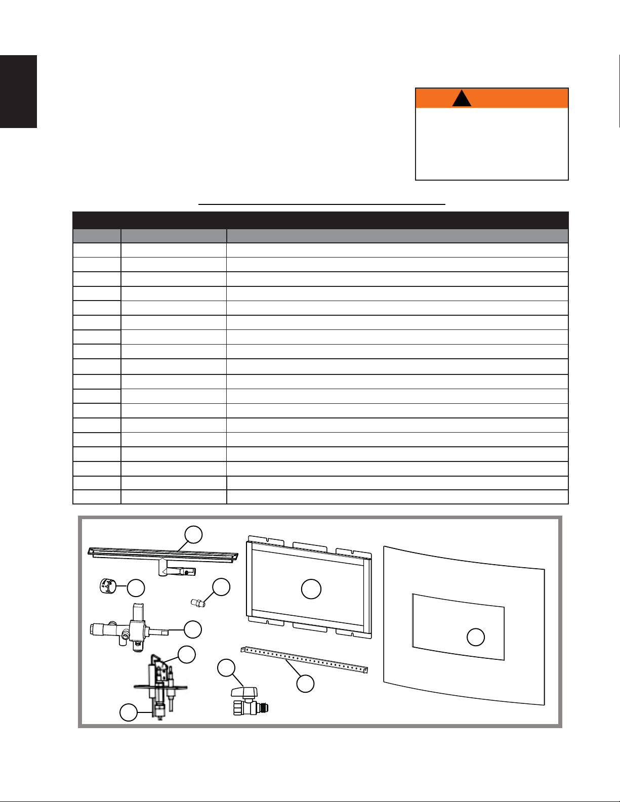
* IDENTIFIES ITEMS WHICH ARE NOT ILLUSTRATED. FOR FURTHER INFORMATION, CONT ACT YOUR
AUTHORIZED DEALER.
REF NO. PART NO. DESCRIPTION
1
2
3
4*
5
5
6
7
7
8*
9
10
10
11*
12
13*
14* W385-0334 NAPOLEON LOGO
15 W080-1370 MOUNTING BRACKET
G010-0028 ASSEMBLY, BURNER
G010-0032 ASSEMBLY, DOOR
G010-0035 ASSEMBLY, CURVED FRONT GLASS
G137-0001 CERAMIC CATALYST C/W CAN
G240-0002N ODS, NG
G240-0002P ODS, LP
N380-0019B KNOB
W456-0055 BURNER ORIFICE, NG
W456-0066
G490-0001 TUBE, BRASS
G530-0002 VALVE
G530-0003N REGULATOR, NG
G530-0003P REGULATOR, LP
N720-0044 FLEXIBLE CONNECTOR, 12" X 3/8" (304.8mm x 9.5mm)
W725-0046 VALVE, GAS BALL #91-1032
G750-0001 WIRE, ELECTRODE 24" (609.6mm)
COMPONENTS
BURNER ORIFICE, LP
!
WARNING
FAILURE TO POSITION THE PARTS
IN ACCORDANCE WITH THIS
MANUAL OR FAILURE TO USE ONLY
PARTS SPECIFICALLY APPROVED
WITH THIS APPLIANCE MAY
RESULT IN PROPERTY DAMAGE OR
PERSONAL INJURY.
41.1
10
W415-1158 / A / 11.19.13
1
6
7
2
9
3
5
12
15
Page 21

10.0 TROUBLESHOOTING
21
!
WARNING
ALWAYS LIGHT THE PILOT WHETHER FOR THE FIRST TIME OR IF THE GAS SUPPLY HAS RAN OUT,
WITH THE GLASS DOOR OPEN OR REMOVED.
TURN OFF THE GAS AND ELECTRICAL POWER BEFORE SERVICING THE APPLIANCE.
APPLIANCE MAY BE HOT, DO NOT SERVICE UNTIL APPLIANCE HAS COOLED.
DO NOT USE ABRASIVE CLEANERS.
SYMPTOM PROBLEM TEST SOLUTION
Pilot will not light. Wiring. - Verify the wire for the electrode and ignitor are
THERMOCOUPLE
ELECTRODE
PILOT TUBE
Pilot sparks but
will not light.
Loose connection. - Verify no loose connections, electrical shorts in the
Igniter Spark gap is
incorrect.
Gas supply. - Verify that the incoming gas line ball valve is “Open”.
Out of propane gas. - Fill the tank.
connected.
wiring or ground out to any metal object.
- Spark gap of the ignitor to the pilot should be 1/8”
(3.2mm).
Verify that the inlet pressure reading is within
acceptable limits, inlet pressures must not exceed
14” W.C.(34.9mb)
EN
Carbon is being
deposited on
glass, logs,
rocks, media
or combustion
chamber surfaces.
White / grey fi lm
forms.
Noisy Burner Media Placement. - In some installations, the glass media can lead to
Air shutter has become
blocked.
Flame is impinging on the
glass, logs, rocks, media
or combustion chamber.
Sulphur from fuel is being
deposited on glass, logs or
combustion chamber
surfaces.
- Ensure air shutter opening is free of lint or other
obstructions.
- Check that the glass, logs, rocks or media are
correctly positioned.
- Open air shutter to increase the primary air.
- Check the input rate: check the manifold pressure
and orifi ce size as specifi ed in the instructions.
- Check that the door gasketing is not broken or
missing and that the seal is tight.
- Clean the glass, see “CARE OF GLASS” section
DO NOT CLEAN GLASS WHEN HOT.
- If deposits are not cleaned off regularly, the glass
may become permanently marked.
a “puffi ng” sound. Simply remove media covering
burner ports.
42.32
W415-1158 / A / 11.19.13
Page 22

22
11.0 WARRANTY
EN
NAPOLEON® products are manufactured under the strict Standard of the world recognized ISO 9001 : 2008 Quality Assurance
Certifi cate.
NAPOLEON® products are designed with superior components and materials assembled by trained craftsmen who take great
pride in their work. The burner and valve assembly are leak and test-fi red at a quality test station. The complete appliance is
again thoroughly inspected by a qualifi ed technician before packaging to ensure that you, the customer, receives the quality
product that you expect from NAPOLEON®.
NAPOLEON® GAS APPLIANCE PRESIDENT’S LIFETIME LIMITED WARRANTY
The following materials and workmanship in your new NAPOLEON® gas appliance are warranted against defects for as long as
you own the appliance. This covers: combustion chamber, heat exchanger, stainless steel burner, phazer™ logs and embers, rocks,
ceramic glass (thermal breakage only), gold plated parts against tarnishing, porcelainized enameled components and aluminum
extrusion trims.*
Electrical (110V and millivolt) components and wearable parts such as blowers, gas valves, thermal switch, switches, wiring, remote
controls, ignitor, gasketing, and pilot assembly are covered and NAPOLEON® will provide replacement parts free of charge during
the fi rst year of the limited warranty.*
Labour related to warranty repair is covered free of charge during the fi rst year. Repair work, however, requires the prior approval of
an authorized company offi cial. Labour costs to the account of NAPOLEON® are based on a predetermined rate schedule and any
repair work must be done through an authorized NAPOLEON® dealer.
* Construction of models vary. Warranty applies only to components included with your specifi c appliance.
CONDITIONS AND LIMITATIONS
NAPOLEON® warrants its products against manufacturing defects to the original purchaser only. Registering your warranty is not necessary. Simply
provide your proof of purchase along with the model and serial number to make a warranty claim. NAPOLEON® reserves the right to have its
representative inspect any product or part thereof prior to honouring any warranty claim. Provided that the purchase was made through an authorized
NAPOLEON® dealer your appliance is subject to the following conditions and limitations:
Warranty coverage begins on the date of original installation.
This factory warranty is non-transferable and may not be extended whatsoever by any of our representatives.
The gas appliance must be installed by a licensed, authorized service technician or contractor. Installation must be done in accordance with the installation
instructions included with the product and all local and national building and fi re codes.
This limited warranty does not cover damages caused by misuse, lack of maintenance, accident, alterations, abuse or neglect and parts installed from
other manufacturers will nullify this warranty.
This limited warranty further does not cover any scratches, dents, corrosion or discoloring caused by excessive heat, abrasive and chemical cleaners nor
chipping on porcelain enamel parts, mechanical breakage of PHAZER™ logs and embers.
This warranty extends to the repair or replacement of warranted parts which are defective in material or workmanship provided that the product has been
operated in accordance with the operation instructions and under normal conditions.
After the fi rst year, with respect to this President’s Lifetime Limited Warranty, NAPOLEON® may, at its discretion, fully discharge all obligations with
respect to this warranty by refunding to the original warranted purchaser the wholesale price of any warranted but defective part(s).
NAPOLEON® will not be responsible for installation, labour or any other expenses related to the reinstallation of a warranted part and such expenses are
not covered by this warranty.
Notwithstanding any provisions contained in the President’s Lifetime Limited Warranty, NAPOLEON’S responsibility under this warranty is defi ned as
above and it shall not in any event extend to any incidental, consequential or indirect damages.
This warranty defi nes the obligations and liability of NAPOLEON® with respect to the NAPOLEON® gas appliance and any other warranties expressed or
implied with respect to this product, its components or accessories are excluded.
NAPOLEON® neither assumes, nor authorizes any third party to assume, on its behalf, any other liabilities with respect to the sale of this product.
NAPOLEON® will not be responsible for: over-fi ring, downdrafts, spillage caused by environmental conditions such as rooftops, buildings, nearby trees,
hills, mountains, inadequate vents or ventilation, excessive venting confi gurations, insuffi cient makeup air, or negative air pressures which may or may not
be caused by mechanical systems such as exhaust fans, furnaces, clothes dryers, etc.
Any damages to the appliance, combustion chamber, heat exchanger, plated trim or other components due to water, weather damage, long periods of
dampness, condensation, damaging chemicals or cleaners will not be the responsibility of NAPOLEON®.
All parts replaced under the President’s Limited Lifetime Warranty Policy are subject to a single claim.
During the fi rst 10 years NAPOLEON® will replace or repair the defective parts covered by the lifetime warranty at our discretion free of charge. From 10
years to life, NAPOLEON® will provide replacement parts at 50% of the current retail price.
All parts replaced under the warranty will be covered for a period of 90 days from the date of their installation.
The manufacturer may require that defective parts or products be returned or that digital pictures be provided to support the claim. Returned products are
to be shipped prepaid to the manufacturer for investigation. If a product is found to be defective, the manufacturer will repair or replace such defect.
Before shipping your appliance or defective components, your dealer must obtain an authorization number. Any merchandise shipped without
authorization will be refused and returned to sender.
Shipping costs are not covered under this warranty.
Additional service fees may apply if you are seeking warranty service from a dealer.
Warranty labour allowance is only for the replacement of the warranted part. Travel, diagnostic tests, shipping and other related charges are not covered
by this warranty.
ALL SPECIFICATIONS AND DESIGNS ARE SUBJECT TO CHANGE WITHOUT PRIOR NOTICE DUE TO ON-GOING PRODUCT
IMPROVEMENTS. NAPOLEON® IS A REGISTERED TRADEMARK OF WOLF STEEL LTD.
2.16
W415-1158 / A / 11.19.13
Page 23

12.0 SERVICE HISTORY
23
EN
43.1
W415-1158 / A / 11.19.13
Page 24

Products
®
Other Napoleon
Fireplace Inserts • Charcoal Grills • Gas Fireplaces • Waterfalls • Wood Stoves
Heating & Cooling • Electric Fireplaces • Outdoor Fireplaces • Gourmet Grills
24 Napoleon Road, Barrie, Ontario, Canada L4M 0G8
214 Bayview Drive, Barrie, Ontario, Canada L4N 4Y8
103 Miller Drive, Crittenden, Kentucky, USA 41030
7200 Trans Canada Highway, Montreal, Quebec, Canada H4T 1A3
Fireplaces / Heating & Cooling call: 705-721-1212 • Grills call: 705-726-4278
napoleonproducts.com
 Loading...