

Page 1
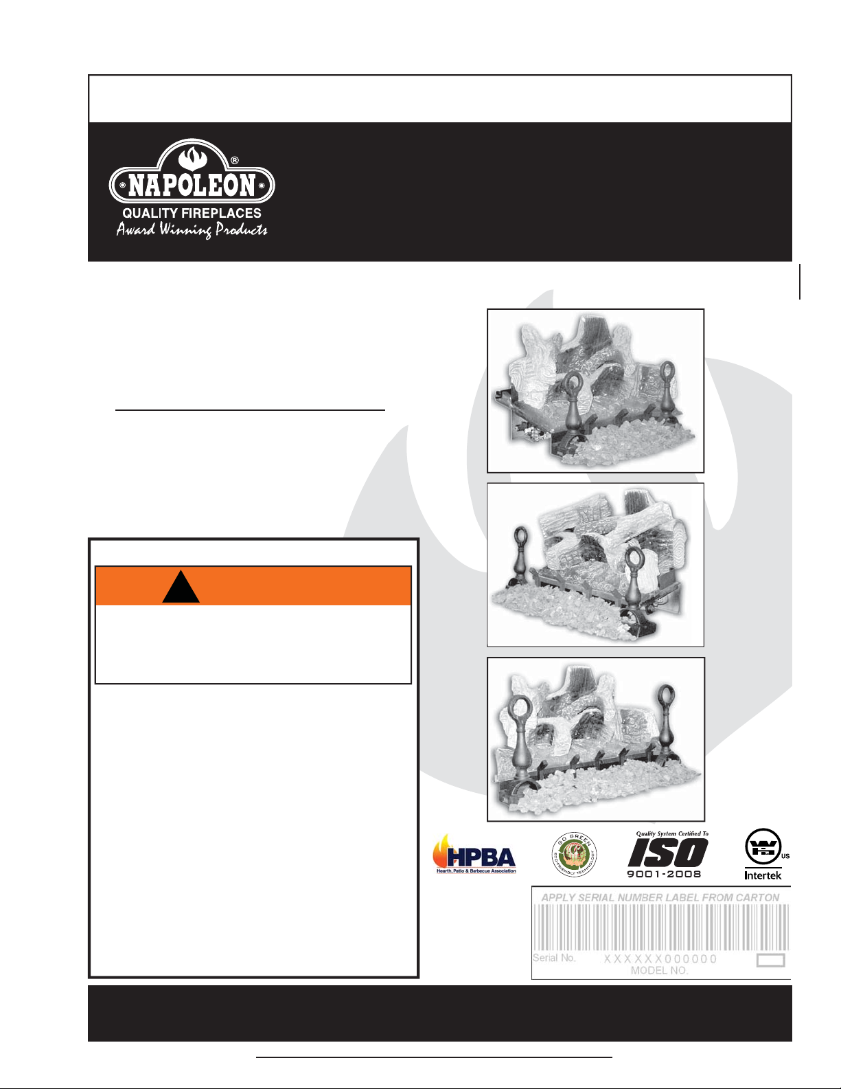
These log sets can be installed in vented or unvented applications. See installation details for the
particular application that applies.
INSTALLER: LEAVE THIS MANUAL WITH THE APPLIANCE.
CONSUMER: RETAIN THIS MANUAL FOR FUTURE REFERENCE.
INSTALLATION AND
OPERATING INSTRUCTIONS
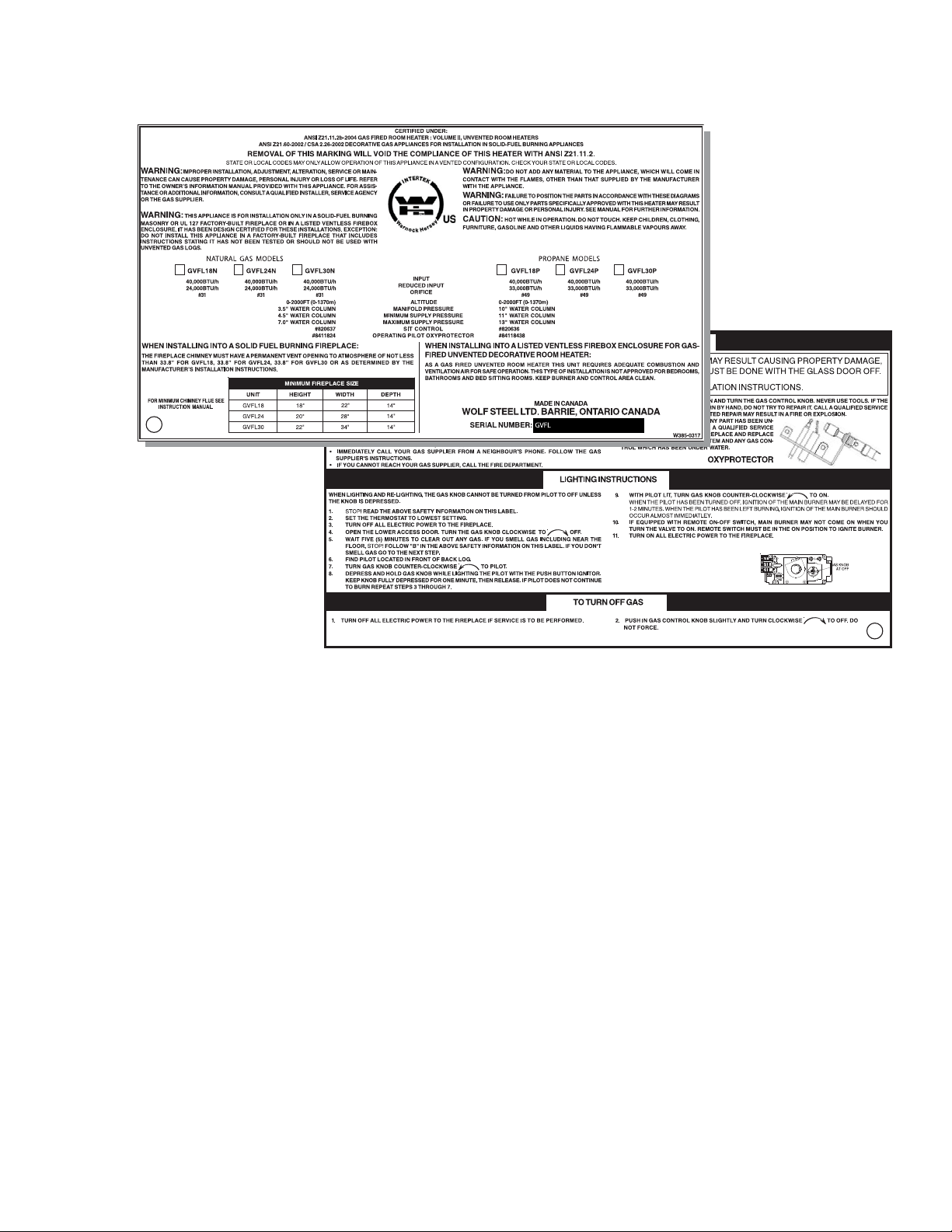
CERTIFIED UNDER: ANSI Z21.11.2a-2008 GAS FIRED ROOM HEATER : VOLUME II, UNVENTED ROOM HEATERS
ANSI Z21.60b-2004 / CSA 2.26b-2004 DECORATIVE GAS APPLIANCES FOR INSTALLATION IN SOLID-FUEL BURNING APPLIANCES
GVFL18N, GVFL24N,
GVFL30N
NATURAL GAS
1
GVFL18P, GVFL24P,
GVFL30P
PROPANE
CERTIFIED FOR THE UNITED STATES USING ANSI METHODS.
SAFETY INFORMATION
!
WARNING
If the information in these instructions are
not followed exactly, a fi re or explosion
may result causing property damage,
personal injury or loss of life.
- Do not store or use gasoline or other fl ammable
vapors and liquids in the vicinity of this or any
other appliance.
- WHAT TO DO IF YOU SMELL GAS:
• Do not try to light any appliance.
• Do not touch any electrical switch; do not use
any phone in your building.
• Immediately call your gas supplier from a
neighbour’s phone. Follow the gas supplier’s
instructions.
• If you cannot reach your gas supplier, call the
fi re department.
- Installation and service must be performed by a
qualifi ed installer, service agency or the supplier.
- This is an unvented gas-fi red heater that
uses air (oxygen) from the room in which it is
installed. Provisions for adequate combustion and
ventilation air must be provided.
GVFL18
GVFL24
GVFL30
$10.00
Wolf Steel Ltd., 24 Napoleon Rd., Barrie, ON, L4M 4Y8 Canada /
103 Miller Drive, Crittenden, Kentucky, USA, 41030
Phone (705)721-1212 • Fax (705)722-6031 • www.napoleonfi replaces.com • ask@napoleonproducts.com
1.3A
W415-0809 / A / 05.10.10
Page 2

2
TABLE OF CONTENTS
1.0 INSTALLATION OVERVIEW 3
2.0 INTRODUCTION 4
2.1 GENERAL INSTRUCTIONS 5
2.2 GENERAL INFORMATION 6
2.3 MINIMUM APPLIANCE SIZE 6
2.4 RATING PLATE INFORMATION 7
3.0 INSTALLATION 8
3.1 INSTALLING IN AN UNVENTED APPLICATION 8
3.1.1 COMBUSTION AND VENTILATION AIR PROVISIONS 8
3.1.2 DETERMINING CONFINED OR UNCONFINED SPACE 8
3.2 INSTALLING IN A VENTED APPLICATION 10
3.2.1 DAMPER STOP INSTALLATION 10
3.3 GAS PIPING 11
4.0 FINISHING 11
4.1 ANDIRON AND GRATE ASSEMBLY 11
4.2 LOG PLACEMENT 12
4.3 LOGO PLACEMENT 13
4.4 MEDIA 13
5.0 OPERATING INSTRUCTIONS 14
5.1 LIGHTING INSTRUCTIONS 14
5.2 MATCH LIGHTING INSTRUCTIONS 14
6.0 OPERATION 15
7.0 ADJUSTMENTS 16
7.1 AIR SHUTTER 16
7.2 FLAME CHARACTERISTICS 16
8.0 MAINTENANCE 16
8.1 OXYGEN DEPLETION SENSOR (ODS) CLEANING 16
9.0 REPLACEMENTS 17
10.0 TROUBLE SHOOTING 19
11.0 WARRANTY 22
12.0 SERVICE HISTORY 23
NOTE: Changes, other than editorial, are denoted by a vertical line in the margin.
W415-0809 / A / 05.10.10
Page 3
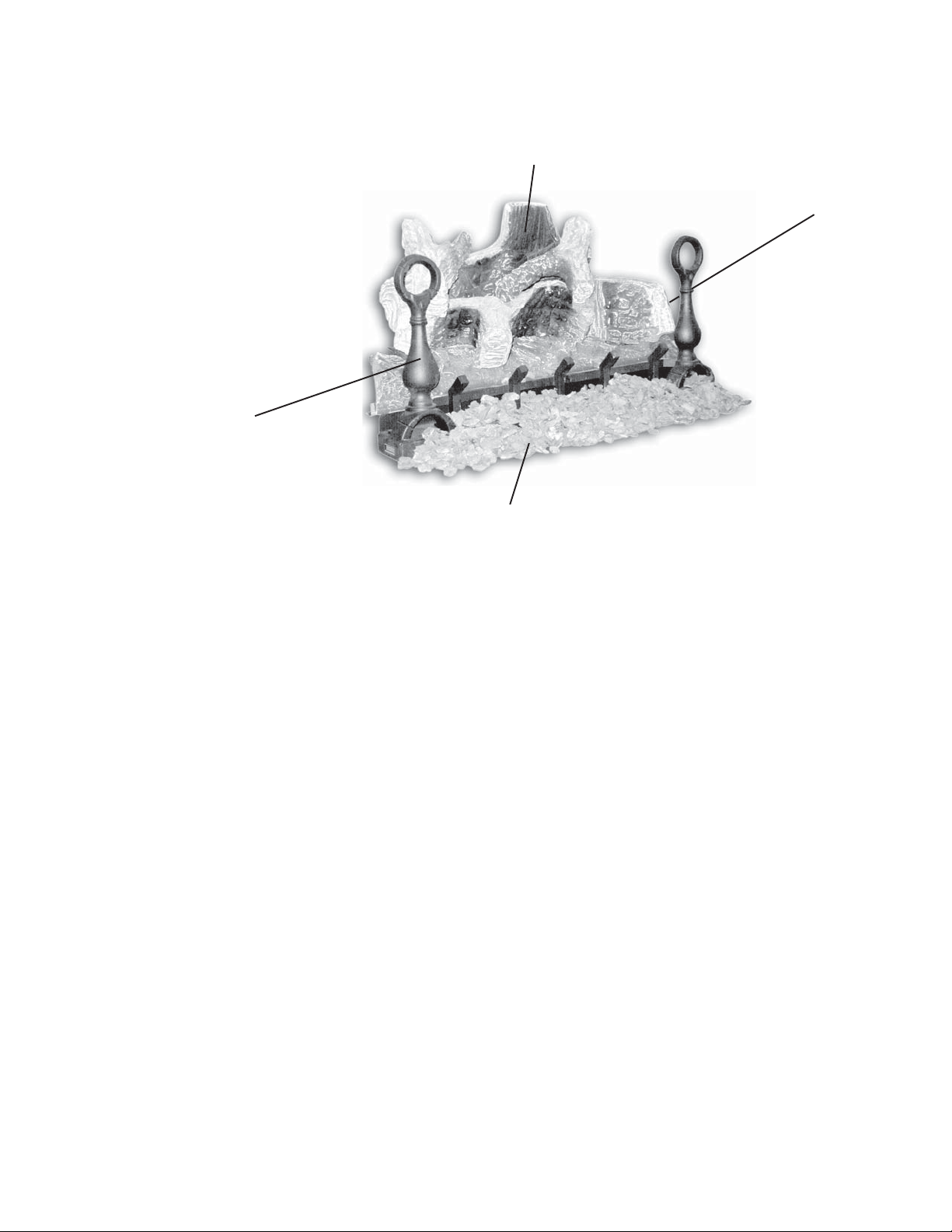
1.0 INSTALLATION OVERVIEW
Logs, see “LOG PLACEMENT”
section.
Andiron, see “ANDIRON AND
GRATE ASSEMBLY” section.
3
Rating Plate, see “RATING
PLATE INFORMATION”
section.
Media, see “MEDIA” section.
W415-0809 / A / 05.10.10
Page 4

4
2.0 INTRODUCTION
• THIS APPLIANCE IS HOT WHEN OPERATED AND CAN CAUSE SEVERE BURNS IF CONTACTED.
• ANY CHANGES TO THIS APPLIANCE OR ITS CONTROLS CAN BE DANGEROUS AND IS PROHIBITED.
• Under no circumstances should this appliance be modifi ed.
• Do not operate appliance before reading and understanding operating instructions. Failure to operate appliance
according to operating instructions could cause fi re or injury.
• Risk of burns. The appliance should be turned off and cooled before servicing.
• Do not install damaged, incomplete or substitute components.
• Risk of cuts and abrasions. Wear protective gloves and safety glasses during installation. Sheet metal edges may
be sharp.
• Provide adequate ventilation and combustion air. Provide adequate clearance for servicing and operating this
appliance. Never obstruct the front opening of the appliance.
• If the appliance shuts off, do not re-light until you provide fresh air. If the appliance keeps shutting of f, have it
serviced. Keep burner and control compartment clean.
• Do not burn wood or other materials in this appliance.
• Young children should be carefully supervised when they are in the same room as the appliance. Toddlers, young
children and others may be susceptible to accidental contact burns. A physical barrier is recommended if there are
at risk individuals in the house. To restrict access to an appliance, install an adjustable safety gate to keep toddlers,
young children and other at risk individuals out of the room and away from hot surfaces.
• Due to high temperatures, the appliance should be located out of traffi c and away from furniture and draperies.
• Ensure you have incorporated adequate safety measures to protect infants/toddlers from touching hot surfaces.
• Clothing or other fl ammable material should not be placed on or near the appliance.
• Check with your local hearth specialty dealer for safety screens and hearth guards to protect children from hot
surfaces. These screens and guards must be fastened to the fl oor.
• Any safety screen or guard removed for servicing must be replaced prior to operating the appliance.
• It is imperative that the control compartments, burners and circulating blower and its passageway in the appliance
are kept clean. The appliance should be inspected before use and at least annually by a qualifi ed service person.
More frequent cleaning may be required due to excessive lint from carpeting, bedding, material, etc. The appliance
area must be kept clear and free from combustible materials, gasoline and other fl ammable vapours and liquids.
• Furniture or other objects must be kept a minimum 4 feet away from the front of the appliance.
• Do not use this appliance if any part has been under water. Immediately call a qualifi ed service technician to inspect
the appliance and to replace any part of the control system and any gas control which has been under water.
• Do not allow fans to blow directly into the appliance. Avoid any drafts that alter burner fl ame patterns.
• Do not use a blower insert, heat exchanger insert or any other accessory not approved for use with this appliance.
• Carbon or soot should not occur in a vent free appliance as it can distribute into the living area of your home. If you
notice any signs of carbon or soot, immediately turn off your appliance and arrange to have it serviced by a qualifi ed
technician before operating it again.
• Keep the packaging material out of reach of children and dispose of the material in a safe manner. As with all plastic
bags, these are not toys and should be kept away from children and infants.
• As with any combustion appliance, we recommend having your appliance regularly inspected and serviced as well
as having a Carbon Monoxide Detector installed in the same area to defend you and your family against Carbon
Monoxide.
• The gas log appliance must be secured to the appliance fl oor to ensure that the position is not changed while
adjusting the controls.
• Sooting and an improper burn may result from shifting of the gas logs by moving the appliance. A gas leak could be
caused by moving the appliance.
• If you are installing the appliance into a sunken application, you must raise the appliance fl oor to allow access to the
gas log controls. Raising the fl oor ensures adequate air fl ow and guards against sooting. The appliance fl oor must
be raised using noncombustible materials.
• This appliance is for installation only in a solid-fuel burning masonry or UL 127 factory-built appliance or in a listed
ventless fi rebox enclosure. It has been design certifi ed for these installations. Exception: DO NOT install this
appliance in a factory-built appliance that includes instructions stating it has not been tested or should not be used
with unvented gas logs.
• This appliance is only for use with the type of gas indicated on the rating plate. This appliance is not convertible for
use with other gases.
• A appliance screen must be in place when the appliance is operating and, unless other provisions for combustion air
are provided, the screen shall have an opening for introduction of combustion air.
• State or local codes may only allow operation of this appliance in a vented confi guration. Check your state or local
codes.
!
WARNING
3.12
W415-0809 / A / 05.10.10
Page 5
2.1 GENERAL INSTRUCTIONS
ALWAYS LIGHT THE PILOT WHETHER FOR THE FIRST TIME OR IF THE GAS SUPPLY HAS RAN OUT,
WITH THE GLASS DOOR OPENED OR REMOVED.
PROVIDE ADEQUATE CLEARANCE FOR SERVICING AND OPERATING THE APPLIANCE.
NEVER OBSTRUCT THE FRONT OPENING OF THE APPLIANCE.
OBJECTS PLACED IN FRONT OF THE APPLIANCE MUST BE KEPT A MINIMUM OF 48” FROM THE
SURFACES AROUND AND ESPECIALLY ABOVE THE APPLIANCE CAN BECOME HOT. AVOID CONTACT
WHEN THE APPLIANCE IS OPERATING.
HIGH PRESSURE WILL DAMAGE VALVE. DISCONNECT GAS SUPPLY PIPING BEFORE PRESSURE TESTING
GAS LINE AT TEST PRESSURES ABOVE 1/2 PSIG. CLOSE THE MANUAL SHUT-OFF VALVE BEFORE
PRESSURE TESTING GAS LINE AT TEST PRESSURES EQUAL TO OR LESS THAN 1/2 PSIG.
!
WARNING
PROVIDE ADEQUA TE VENTILA TION.
FRONT FACE OF THE UNIT.
FIRE RISK. EXPLOSION HAZARD.
5
USE ONLY WOLF STEEL APPROVED OPTIONAL ACCESSORIES AND REPLACEMENT PARTS WITH THIS APPLIANCE.
USING NON-LISTED ACCESSORIES (BLOWERS, DOORS, LOUVRES, TRIMS, GAS COMPONENTS, VENTING
COMPONENTS, ETC.) COULD RESULT IN A SAFETY HAZARD AND WILL VOID THE WARRANTY AND CERTIFICATION.
Thoroughly clean the chimney, fl ue and existing appliance before installing the new appliance into it. Do not
burn solid fuels in any appliance that is equipped with this gas log set.
The installation of this appliance must conform with local codes or in the absence of local codes with the
National fuel gas code ANSI Z.223.1 / NFPA 54.
Do not operate appliance in the presence of gasoline or other fl ammable liquids and vapours. Keep area clear
of other combustible materials. The appliance and its shut off must be disconnected from the gas supply piping
system before any pressure testing of the system is done.
Installation practices vary from region to region and it is important to know the specifi cs that apply to your area,
For example: in Massachusetts State:
• The appliance off valve must be a “T” handle gas cock.
• The fl exible connector must not be longer than 36 inches.
• The appliance is not approved for installation in a bedroom or bathroom unless the appliance is a
direct vent sealed combustion product.
• Unvented room appliance shall be installed in accordance with 527 CMR 30.00 and 248 CMR 3.00
through 7.00.
• Sellers of unvented propane or natural gas-fi red space/room appliances shall provide to each
purchaser a copy of 527 CMR 30.00 upon the sale of the appliance from
http://www.napoleonfi replaces.com/Webshare/installation_manuals/mass_requirements.pdf
• A carbon monoxide detector is required in all rooms containing gas fi red appliances.
This appliance may be installed in an aftermarket, permanently located, manufactured (mobile) home, where
not prohibited by local codes.
W415-0809 / A / 05.10.10
Page 6
6
2.2 GENERAL INFORMATION
CARBON MONOXIDE POISONING MAY LEAD TO DEATH
EARLY SIGNS OF CARBON MONOXIDE POISONING RESEMBLE THE FLU, WITH HEADACHE, DIZZINESS
AND/OR NAUSEA. IF YOU HAVE THESE SIGNS, THE APPLIANCE MAY NOT BE WORKING PROPERLY.
GET FRESH AIR AT ONCE! HAVE APPLIANCE SER VICED.
SOME PEOPLE--PREGNANT WOMEN, PERSONS WITH HEART OR LUNG DISEASE, ANEMIA, THOSE
UNDER THE INFLUENCE OF ALCOHOL, THOSE AT HIGH ALTITUDES--ARE MORE AFFECTED BY
THIS APPLIANCE MUST NOT BE INSTALLED IN A BEDROOM OR BATHROOM.
THE APPLIANCE IS ONLY FOR USE WITH THE TYPE OF GAS INDICATED ON THE RATING PLATE.
THIS APPLIANCE IS NOT CONVERTIBLE FOR USE WITH OTHER GASES.
For your satisfaction, this appliance has been test-fi red to assure its operation and quality!
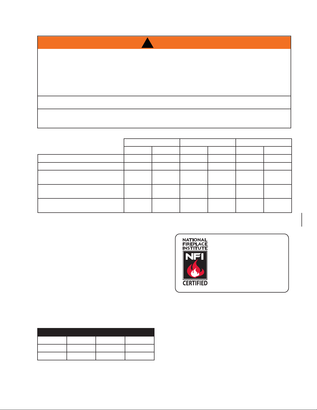
Altitude (FT) 0-4,500 0-4,500 0-4,500 0-4,500 0-4,500 0-4,500
Max input (BTU/HR) 40,000 40,000 40,000 40,000 40,000 40,000
Min Inlet Gas Supply Pressure 4.5“ Water
Max Inlet Gas Supply Pressure 7“ Water
Manifold Pressure (Under Flow
Conditions)
!
WARNING
CARBON MONOXIDE THAN OTHERS.
GVFL18 GVFL24 GVFL30
NG LP NG LP NG LP
Column
Column
3.5“ Water
Column
11“ Water
Column
13“ Water
Column
10“ Water
Column
4.5“ Water
Column
7“ Water
Column
3.5“ Water
Column
11“ Water
Column
13“ Water
Column
10“ Water
Column
4.5“ Water
Column
7“ Water
Column
3.5“ Water
Column
11“ Water
Column
13“ Water
Column
10“ Water
Column
This appliance is for installation in a solid fuel burning fi replace or listed ventless fi rebox enclosures only.
No external electricity (110 volts or 24 volts) is required for
the gas system operation.
This appliance is equipped with a pilot light safety system
referred to as an oxygen depletion sensor (ODS) and is
designed to turn off the appliance if not enough fresh air is
available.
Napoleon’s two vent free fi rebox enclosures the ZCVF
36/42 can be used to house all 3 of Napoleon’s vent free
log sets, the GVFL 18, 24 and 30.
2.3 MINIMUM APPLIANCE SIZE
LOG SET HEIGHT WIDTH DEPTH
GVFL18 18” 22” 14”
GVFL24 20” 28” 14”
GVFL30 22” 34” 14”
We suggest that our gas
hearth products be installed
and serviced by professionals who are certified in
the U.S. by the National
®
Fireplace Institute
www.nficertified.org
Each gas log set must be installed into a appliance cavity
with a minimum size.
Refer to the table to determine the appropriate minimum
appliance size.
NFI Gas Specialists.
(NFI) as
W415-0809 / A / 05.10.10
Page 7
2.4 RATING PLATE INFORMATION
THIS APPLIANCE IS NOT FIELD CONVERTIBLE FOR USE WITH OTHER GASES.
REFERENCE # W/N 15533
7
THE RATING PLATE IS CHAINED TO THE PIEZO IGNITOR BRACKET AND SHOULD BE TUCKED
UNDER THE ENTIRE ASSEMBLY
W415-0809 / A / 05.10.10
Page 8

8
A
3.0 INSTALLATION
3.1 INSTALLING IN AN UNVENTED APPLICATION
!
WARNING
BARRIERS SUCH AS THE BOTTOM OF A GLASS DOOR FRAME PLACED IN FRONT OF A GAS LOG
SET CAN CHANGE THE AIR FLOW CHARACTERISTICS OF THE APPLIANCE WHICH IN TURN CAN
CAUSE THE APPLIANCE TO CARBON OR OVERHEAT AND MALFUNCTION.
During manufacturing, fabricating and shipping various components of this appliance are treated with certain
oils, fi lms or bonding agents.
These materials may produce smoke and smells as they are burned off during the initial operation of the
appliance; possibly causing headaches or eye or lung irritation. This is a normal and temporary occurrence.
Simply open a window to ventilate the room during the burn off period.
3.1.1 COMBUSTION AND VENTILATION AIR PROVISIONS
This appliance shall not be installed in a confi ned space or unusually tight construction unless provisions are
provided for adequate combustion and ventilation air.
The National Fuel Gas Code, ANSI Z223.1 / NFPA 54 defi nes a confi ned space as a space whose volume is
less than 50 cubic feet per 1,000 Btu per hour (4.8 m3 per kw) of the aggregate input rating of all appliances
installed in that space and an unconfi ned space as a space whose volume is not less than 50 cubic feet per
1,000 Btu per hour (4.8 m3 per kw) of the aggregate input rating of all appliances installed in that space.
Rooms communicating directly with the space in which the appliances are installed, through openings not
furnished with doors are considered a part of the unconfi ned space.
17.1A
The GVFL 18/24/30 are all rated at 40,000 BTUs per hour and therefore requires a minimum unconfi ned space
of 2,000 cubic feet.
3.1.2 DETERMINING CONFINED OR UNCONFINED SPACE
This appliance shall not be installed in a room or space unless the required volume of indoor combustion air
is provided by the method described in the National Fuel Gas Code, ANSI Z223.1 / NFPA 54, the International
Fuel Gas Code, or applicable local codes.
To determine the volume of the room where the appliance is to be installed, multiply the width x the length x
the ceiling height of that room measured in feet. If any adjoining rooms are connected by grilles or openings
such as kitchen pass-throughs, etc., the volume of those rooms may be added to the total.
Multiply the room volume by 1000 and divide this amount by 50 to determine the maximum BTU/hr that the
space can support with adequate combustion and ventilation air.
dd the Btu/hr of all fuel burning appliances located within the space such as gas furnace, gas water
appliance, etc. Do not include direct vent gas appliances which draw their input and output air from and to the
outdoors.
!
WARNING
IF THE AREA IN WHICH THE APPLIANCE MAY BE OPERA TED IS SMALLER THAN THAT DEFINED AS
AN UNCONFINED SP ACE OR IF THE BUILDING IS OF UNUSUALLY TIGHT CONSTRUCTION, PROVIDE
ADEQUA TE COMBUSTION AND VENTILATION AIR BY ONE OF THE METHODS DESCRIBED IN THE
NA TIONAL FUEL GAS CODE ANSI Z223.1/ NFPA 54 , AIR FOR COMBUSTION AND VENTILATION, OR THE
APPLICABLE LOCAL CODE.
IF THE AREA IN WHICH THE APPLIANCE MAY BE OPERA TED DOES NOT MEET THE REQUIRED VOLUME
FOR INDOOR COMBUSTION AIR, COMBUSTION AND VENTILATION AIR SHALL BE PROVIDED BY ONE
OF THE METHODS DESCRIBED IN THE ANSI Z223.1 / NFPA 54, THE INTERNATIONAL FUEL GAS CODE,
OR APPLICABLE LOCAL CODES.
W415-0809 / A / 05.10.10
Page 9

Unusually tight construction is defi ned as construction where:
A
LENGTH
HEIGHT
ROOM 2
ROOM 1
WIDTH
A) Walls and ceilings exposed to the outside atmosphere have a continuous water vapour retarder with a
rating of 1 perm (6 x 10-11 kg per pa-sec-m2) or less with openings gasketed or sealed, and
B) Weather stripping has been added on openable windows and doors, and
C) Caulking or sealants are applied to areas such as joints around window and door frames, between sole
plates and fl oors, between wall-ceiling joints, between wall panels, at penetrations for plumbing, electrical,
and gas lines, and at other openings.
n unvented room appliance is recommended for use as a secondary heat source rather than as a primary
source. Gas combustion produces water vapour which could occur at the rate of approximately one ounce of
water for every 1,000 BTU/hr of gas input. During the cold weather season, indoor humidity levels tend to be
low. Consequently, this water vapour can enhance the living space. However if a problem should occur:
A) Ensure suffi cient combustion and circulation air
B) Use a dehumidifi er
C) Do not use the unvented room appliance as a primary heat source
Without suffi cient fresh air for proper operation, poor fuel combustion can result. Carbon Monoxide is a result
of poor combustion.
If additional fresh air is required, use one of the methods described in the National Fuel
Gas Code, ANSI Z223.1, Section 5.3 or the applicable local code.
Room Volume = Length x Width x Height
Max BTU/hr = Room Volume x 1000 / 50
If for example:
The length of the rooms is 10 feet,
The width of Room 1 is 10 feet,
The width of Room 2 is 15 feet,
The height of the rooms is 8 feet.
9
The volume of Room 1: 10x10x8 = 800 cubic feet
The volume of Room 2: 10x15x8 = 1200 cubic feet
19.1A
EXAMPLE 1:
In this example, because there is no door to the adjoining room, the volume of the adjoining room may be
added to the volume of the room with the heater to get a total unconfi ned space.
The total unconfi ned space: 800 + 1200 = 2000 cubic feet.
Maximum BTU/h: 2000x1000 = 40,000 BTU/h
50
19.2
If there are no more fuel burning appliances within this space then the 40,000 BTU/h input of the appliance is
suitable to be installed. This also assumes that the construction of this space is not unusually tight.
EXAMPLE 2:
If in this example a solid door separates Room 1 from Room 2, the volume of Room 2 could not be used. In
this case the maximum BTU/h would be:
Maximum BTU/h: 800x1000 = 16,000 BTU/h
50
19.3
This would be considered a confi ned space since it can not support the 40,000 BTU/h input of the appliance
and it would be necessary to provide adequate combustion and ventilation air to Room 1.
W415-0809 / A / 05.10.10
Page 10

10
3.2 INSTALLING IN A VENTED APPLICATION
The appliance and gas logs function as a system. If the appliance is not drafting properly and spilling into the
room (check with a match or a smoke stick), reposition the damper clamp until a positive draft is obtained by
opening the damper. If negative pressure in home prevents having a positive draft, consult an air quality specialist.
3.2.1 DAMPER STOP INSTALLATION
!
WARNING
BEFORE INST ALLING IN A SOLID FUEL BURNING FIREPLACE, THE CHIMNEY AND FIREBOX MUST BE
CLEANED OF SOOT, CREOSOTE, ASHES, AND LOOSE PAINT BY A QUALIFIED CHIMNEY CLEANER.
The damper must be permanently locked in
position to prevent full closure and to provide
a minimum fl ue opening. Various methods
for locking the damper may be used but may
be restricted from region to region and it is
important to know the specifi cs that apply to
your area. For your convenience a damper stop
is provided with the appliance and may be used
where not prohibited by state or local codes.
Use the 3” adjustable bolt to adjust the damper to the
correct opening, based on the enclosed chart.
Should the damper stop not fi t, or provide the required
permanent opening from the Minimum Damper Opening
table, have the damper cut to provide a minimum
permanent opening or install an alternate stop.
Any outside air ducts and/or ash dumps in the appliance
shall be permanently closed at time of appliance
installation.
DAMPER STOP
DAMPER
MINIMUM DAMPER OPENING
(SQUARE INCHES)
CHIMNEY
HEIGHT
6 33.8”
8 31.2”
10 28.7” 22.1”
15 26.1” 17.3”
20 23.7” 14.5”
25 22.7” 12.6”
30 21.6” 11.3”
35 10.8”
40 10.2”
MASONRY
APPLIANCE
FACTORY BUILT
APPLIANCE
W415-0809 / A / 05.10.10
Page 11

3.3 GAS PIPING
1
2
DO NOT CONNECT EITHER THE WALL SWITCH, THERMOSTAT OR GAS VALVE TO ELECTRICITY
This appliance and it’s appliance main valve must be disconnected from the gas supply piping system during
any pressure testing of that system at test pressures in excess of ½ PSI (3.5kPa)
!
WARNING
(110 VOLTS).
11
This appliance must be isolated from the gas supply piping
system by closing the individual manual shut off valve during any
pressure testing of the gas supply piping system at test pressure
equal to or less than ½ psi (3.5 kPa)
3.31 Centre the appliance in the appliance opening, making
sure the appliance has enough room behind it for the gas
line to run behind the log set under the log support.
3.3.2 Route the gas line and sizing using piping ½” diameter or
greater to allow the full volume of gas to the appliance.
The routing of the gas line has to be done to local and /
or national codes.
3.3.3 When rigid pipe is used an ANSI approved manual shut
off and a union must be installed upstream within the
appliance cavity.
3.3.4 To ensure the appliance operates reliably install a sediment trap upstream of the appliance within the
structures of the piping system.
3.3.5 When using propane, a regulator must be used between the tank and the outside wall of the house to
ensure the line pressure does not exceed 14” w.c.
Regulator
Fireplace
3"
Union
Sediment
Trap
Manual
Shut-Off
Valve
Fireplace
Wall
Shut-Off
Key
3.3.6 Check gas connections with a gas detection device to test for leaks in the system. Soapy water
mixture can also be used to check for leaks.
3.3.7 Once all the gas connections are tested for leaks, start the appliance. Follow the lighting instructions
to ensure the appliance is working properly before fi nishing.
4.0 FINISHING
4.1 ANDIRON AND GRATE ASSEMBLY
4.1.1 With the 2 andirons laying face
down, secure the grate overtop
using 2x ¼-20 bolts (supplied in the
manual baggie).
4.1.2 Install the grate/andiron assembly
to the burner base using 4x ¾” self
tapping screws (supplied in the
manual baggie).
USE ONLY ACCESSORIES
DESIGNED FOR AND
LISTED WITH YOUR
SPECIFIC LOG SET.
W415-0809 / A / 05.10.10
Page 12

12
4.2 LOG PLACEMENT
Failure to position these logs in accordance with these diagrams or failure to use parts specifi cally
approved with this appliance may result in property damage or personal injury.
Do not place glowing embers, charcoal embers, vermiculite or charcoal lumps on this burner.
PhazerTM logs, exclusive to Napoleon Appliances, provide a unique and realistic glowing effect that is different
in every installation. These logs are fuel specifi c. Do not interchange. Refer to the replacement parts list.
Failure to follow these log placement instructions may cause sooting.
!
WARNING
4.2.1 Place the fi bre burner
cover onto the two locating studs screwed into the
pan burner.
4.2.4 Position the slotted cav-
ities on the bottom of
log #3 onto the slotted
projections shown. The
charred face should be
facing in.
4.2.2 Place the rear log #1 onto
the locating studs on the
rear log support.
4.2.5 Position the bottom cavity
of log #4 onto the bridge
(top right corner of fi bre
burner cover) as shown,
with the charred face
inward.
4.2.3 Position the holes on the
bottom of log #2 onto the
fi bre embosses shown.
4.2.6 Position the pins on the
bottom of log #5 into the
holes on the left end of
log #1 and the left end of
log #2.
4.2.7 Place the end of log #6
on the right end of log
#1. The fork in the log
should straddle the knot
on top of the log #2.
W415-0809 / A / 05.10.10
Log colours may vary. During the initial use of the appliance, the colours will become more uniform as colour pigments burn in during the
heat activated curing process.
Positioning the logs improperly will cause fl ame impingement and
carboning.
Blocked burner ports can cause an incorrect fl ame pattern, carbon de-
posits and delayed ignition. PhazerTM logs glow when exposed to direct
fl ame. Use only certifi ed PhazerTM logs available from your authorized
dealer/distributor.
Page 13

4.3 LOGO PLACEMENT
LOGO
½"
Remove the backing of the logo supplied. Centre the logo
on the front of the appliance, ½” in from the left side, as
shown.
13
½"
LOG
O
4.4 MEDIA
4.4.1 Place lava or ember rock around the base of the appli-
4.4.2 Place formed charcoal lumps around the front and sides
4.4.3 Use remaining lava or ember rock to blend with the char-
4.4.4 GVFL30 ONLY: Sprinkle remaining lava rock onto the
GVFL 18
ance, making sure not to block any burner ports or valve
access. Retain a small amount of lava rock for step 3 and
if applicable step 4.
of the appliance.
coal lumps.
GVFL 24
outer fi bre ember beds to hide the seam.
GVFL 30
W415-0809 / A / 05.10.10
Page 14

14
5.0 OPERATING INSTRUCTIONS
If the appliance is equipped with decorative glass doors, they must be fully opened when operating this gas log
set.
5.1 LIGHTING INSTRUCTIONS
5.1.1 Locate the pilot burner at the rear of the log set on the right
side.
5.1.2 Turn the gas control knob to the pilot setting
(on the left side of the appliance closest to the
back).
5.1.3 With the control knob depressed, push the
piezo igniter continuously until the pilot lights.
Hold the control knob in for 1 minute and release. If the pilot goes out, repeat steps 2 and
3.
5.1.4 Once the pilot stays burning, make certain that
the on / off switch is in the off position. Turn
the control knob counter-clockwise to the on
position.
5.1.5 Turn the on / off switch to the on position to ignite the
burner. This appliance must be isolated from the gas supply
piping system by closing the individual manual shut off valve
during any pressure testing of the gas supply piping system at test pressure equal to or less than ½ psi
(3.5 kPa).
If appliance shuts off, do not relight until you provide fresh air. If appliance keeps shutting off, have it serviced.
Keep burner and control compartment clean.
When lit for the fi rst time, the appliance will emit a slight odour for a few hours. This is a normal temporary con-
dition caused by the curing of the logs and the “burn-off” of internal paints and lubricants used in the manufacturing process and will not occur again. Open a window to ventilate the room during this burn off period.
1
2
3
4
5
5.2 MATCH LIGHTING INSTRUCTIONS
5.2.1 Remove any items necessary for easy access to the ODS (for example: logs, screens, etc.).
5.2.2 Follow appropriate lighting instructions found previously. Instead of pushing and releasing the piezo
button, light a match and hold the fl ame to the end of the pilot and ignite the pilot.
5.2.3 After control knob has been released and pilot stays lit, reinstall any items that were removed for pilot
access.
5.2.4 Call a qualifi ed service technician for repair or replacement of the piezo ignitor.
After extended periods of non-operation such as following a vacation or a warm weather season, the appliance
may emit a slight odour for a few hours. This is caused by dust particles burning off. In both cases, open a
window to suffi ciently ventilate the room.
Purge the gas line with the glass door open. Assure that a continuous gas fl ow is at the burner before closing
the door.
W415-0809 / A / 05.10.10
Page 15

6.0 OPERATION
,)<28'2127)2//2:7+(6(,16758&7,216(;$&7/<$),5(25(;3/26,210$<5(68/7
&$86,1*3523(57<'$0$*(3(5621$/,1-85<25/2662)/,)(
,)$33/,&$%/($/:$<6/,*+77+(3,/27:+(7+(5)257+(),5677,0(25,)7+(*$66833/<+$6
581287:,7+7+(*/$66'22523(1('255(029('
,IDSSOLDQFHVKXWVRIIGRQRWUHOLJKWXQWLO\RXSURYLGHIUHVKDLU,IDSSOLDQFHNHHSVVKXWWLQJRIIKDYHLWVHUYLFHG.HHSEXUQHU
DQGFRQWUROFRPSDUWPHQWFOHDQ
When lit for the first time, the appliance will emit a slight odour for a few hours. This is a normal temporary condition caused by the curing
of the logs and the “burn-in” of internal paints and lubricants used in the manufacturing process and will not occur again. After extended
periods of non-operation such as following a vacation or a warm weather season, the appliance may emit a slight odour for a few hours.
This is caused by dust particles burning off. In both cases, open a window to sufficiently ventilate the room.
FOR YOUR SAFETY READ BEFORE LIGHTING:
Ɣ This appliance is equipped with a pilot which must be lit by hand while following these instructions exactly.
Ɣ
Before operating smell all around the appliance area for gas and next to the floor because some gas is heavier than air and will settle on the floor.
Ɣ Use only your hand to push in and turn the gas control knob. Never use tools. If the knob will not push in and turn by hand, do not try
to repair it. Call a qualified service technician. Force or attempted repair may result in a fire or explosion.
Ɣ Do not use this appliance if any part has been under water. Immediately call a qualified service technician to inspect the appliance
and replace any part of the control system and any gas control which has been under water.
ƔDo not try to light any appliance.
ƔDo not touch any electric switch; do not use any phone in your building.
Ɣ Immediately call your gas supplier from a neighbour’s phone. Follow the gas supplier’s instructions.
Ɣ If you cannot reach your gas supplier, call the fire department.
!
WARNING
WHAT TO DO IF YOU SMELL GAS:
15
LIGHTING INSTRUCTIONS:
When lighting and re-lighting, the gas knob cannot be turned from pilot to off unless the knob is depressed.
$ STOP! Read the above safety information on this label.
% Set the thermostat to lowest setting.
& Turn off all electric power to the appliance.
' Open the control door. Turn the gas knob clockwise to off.
( Wait five (5) minutes to clear out any gas. If you smell gas including near the floor, STOP! Follow “B” in the above safety information
on this label. If you don’t smell gas go to the next step.
) Find pilot located in front of the back log.
G. Turn gas knob counter-clockwise to pilot.
H. Depress and hold gas knob while lighting the pilot with the push button ignitor. Keep knob fully depressed for one minute, then
release. If pilot does not continue to burn repeat steps 3 through 7.
, With pilot lit, turn gas knob counter-clockwise to on. When the pilot has been turned off,
ignition of the main burner may be delayed from 1-2 minutes. When the pilot has been left
burning, ignition of the main burner should occur almost immediatley.
- If equipped with remote on-off switch, main burner may not come on when you turn the valve to on. Remote switch must be in
the on position to ignite burner.
K. Turn on all electric power to the appliance.
TO TURN OFF GAS
A. Turn off all electric power to the appliance if service is to be performed.
%Push in gas control knob slightly and turn clockwise to off. Do not force.
47.1
W415-0809 / A / 05.10.10
Page 16

16
7.0 ADJUSTMENTS
7.1 AIR SHUTTER
CARBON CAN BE DISTRIBUTED IN SURROUNDING LIVING AREAS IF THE AIR SHUTTER IS
FAILURE TO KEEP THE PRIMARY AIR OPENING(S) OF THE BURNER (S) CLEAN MAY RESULT IN
!
WARNING
IMPROPERL Y ADJUSTED.
SOOTING AND PROPERTY DAMAGE.
LOG SET AIR SHUTTER
FUEL NG LP
GVFL18 9/32” 7/16”
GVFL24 9/32” 7/16”
GVFL30 9/32” 7/16”
7.2 FLAME CHARACTERISTICS
It’s important to periodically perform a visual check of the pilot and burner fl ames. Compare them to the illustra-
tions provided. If any fl ames appear abnormal call a service person.
8.0 MAINTENANCE
The air shutter settings are factory set for most installations. However,
adjustment may be required depending on fuel type, vent performance and
altitude.
Closing the air shutter will cause a more yellow fl ame, but can lead to
carboning. Opening the air shutter will cause a more blue fl ame, but
can cause fl ame lifting from the burner ports. The fl ame may not appear
yellow immediately; allow 15 to 30 minutes for the fi nal fl ame colour to be
established.
54.5
!
WARNING
TURN OFF THE GAS AND ELECTRICAL POWER BEFORE SERVICING THE APPLIANCE.
Visually inspect the appliance for carbon buildup.
Using a small whisk or brush, brush off the excess carbon and vacuum up or sweep into the garbage.
Check the appliance for broken logs and corrosion of the main burner base.
8.1 OXYGEN DEPLETION SENSOR (ODS) CLEANING
This procedure must be performed by a
qualified service person!
Inspect the pilot for any visible
contamination or debris (usually lint, pet
hair, spider webs, carpet fibre, etc.) and remove.
Disconnect the pilot from the pilot tubing line,
using a 7/16” wrench. Blow out the housing in
the same direction as the gas flow. Re-install
the pilot tube, turn on the gas and check
for leaks.
If this does not improve the performance,
replace the ODS with an exact replacement. The
device is tamper resistant with no field serviceable
parts.
W415-0809 / A / 05.10.10
CORRECT PILOT FLAME
(Clean, stable, pronounced
blue flame).
INCORRECT PILOT FLAME
(Flame lifts upwards,
becomes unstable with more
of an orange tip).
46.1
Page 17

9.0 REPLACEMENTS
Contact your dealer or the factory for questions concerning prices and policies on replacement parts. Normally
all parts can be ordered through your Authorized dealer / distributor.
FOR WARRANTY REPLACEMENT PARTS, A PHOTOCOPY OF THE ORIGINAL INVOICE WILL BE
REQUIRED TO HONOUR THE CLAIM.
When ordering replacement parts always give the following information:
• Model & Serial Number of appliance
• Installation date of appliance
• Part number
• Description of part
• Finish
* IDENTIFIES ITEMS WHICH ARE NOT ILLUSTRATED. FOR
FURTHER INFORMA TION, CONTACT YOUR AUTHORIZED DEALER.
REF NO. GAS LOGS DESCRIPTION
1 W135-0412 #1 - REAR LOG
2 W135-0404 #2 - MIDDLE LOG
3 W135-0413 #3 - FRONT LOG
4 W135-0414 #4 - RIGHT LOG
5 W135-0415 #5 - LEFT CROSSOVER LOG
6 W135-0416 #6 - RIGHT CROSSOVER LOG
7 GL-671 LOG SET
8 W185-0024 GVFL18 GRATE
8 W185-0020 GVFL24 GRATE
8 W185-0023 GVFL30 GRATE
9 W715-0628 GVFL18 / 24 ANDIRONS
9 W715-0629 GVFL30 ANDIRONS
10 W357-0001 PIEZO IGNITOR AND NUT
11 W455-0078 #31 ORIFICE - NG
11 W455-0042 #49 ORIFICE - LP
12 W660-0023 ON / OFF SWITCH
13 W725-0030 VALVE - NG
13 W725-0031 VALVE - LP
14* W385-0334 NAPOLEON LOGO
15 W662-0003 NATURAL GAS - OXYGEN DEPLETION SENSOR
15 W662-0004 PROPANE GAS - OXYGEN DEPLETION SENSOR
16 W135-0394 FIBRE BURNER COVER
17 W010-2120 WELDED BURNER ASSEMBLY
18* W550-0006 LAVA ROCK
19* W550-0002 CHARCOAL LUMPS
20 W010-1288 DAMPER STOP
21* W750-0060 IGNITOR CABLE
22* W720-0093 PILOT TUBE
23* W135-0265 GVFL30 RIGHT EXTENSION LOG
24* W135-0266 GVFL30 LEFT EXTENSION LOG
COMPONENTS
17
!
WARNING
FAILURE TO POSITION THE PARTS
IN ACCORDANCE WITH THIS
MANUAL OR FAILURE TO USE ONLY
PARTS SPECIFICALLY APPROVED
WITH THIS APPLIANCE MAY
RESULT IN PROPERTY DAMAGE OR
PERSONAL INJURY.
41.1
ACCESSORIES
REF NO. GAS LOGS DESCRIPTION
25* GD-660 REMOTE WALL SWITCH W/20” WIRE
26* W690-0001 MILLIVOLT WALL THERMOSTAT
27* W660-0011B ADVANTAGE PLUS HAND HELD REMOTE
28* W660-0026 PROGRAMMABLE TIMER
29* W550-0006 ADDITIONAL LAVA ROCK / CINDERS
W415-0809 / A / 05.10.10
Page 18

18
12
10
8
9
11
13
7
15
17
20
16
1
2
4
5 6
3
W415-0809 / A / 05.10.10
Page 19

10.0 TROUBLE SHOOTING
!
WARNING
ALWAYS LIGHT THE PILOT WHETHER FOR THE FIRST TIME OR IF THE GAS SUPPLY HAS RAN OUT,
WITH THE GLASS DOOR OPEN OR REMOVED.
TURN OFF THE GAS AND ELECTRICAL POWER BEFORE SERVICING THE APPLIANCE.
APPLIANCE MAY BE HOT, DO NOT SERVICE UNTIL APPLIANCE HAS COOLED.
DO NOT USE ABRASIVE CLEANERS.
SYMPTOM PROBLEM TEST SOLUTION
Main burner goes
out; pilot stays on.
Main burner goes
out; pilot goes out.
Pilot goes out
when the gas knob
is released.
The gas valve has
an interlock device
which will not allow
the pilot burner
to be lit until the
thermocouple
has cooled. Allow
approximately 60
seconds for the
thermocouple to
cool.
Pilot fl ame is not large
enough or not engulfi ng
the thermopile.
Thermopile shorting /
loose connection.
Remote wall switch wire
is too long; too much
resistance in the system.
Faulty thermostat or
switch.
Insuffi cient air supply. - Open window or door. (Use one of the methods
Out of propane gas. - Fill the tank.
Pilot fl ame is not large
enough. (Supply pressure
too low.)
System is not correctly
purged.
Out of propane gas. - Fill the tank.
Pilot fl ame is not large
enough. (Supply pressure
too low.)
Thermocouple shorting /
faulty.
Faulty valve / high low
knob does not depress
smoothly.
19
- Ensure adequate supply pressure.
- Replace pilot assembly.
- Clean thermopile connection to the valve.
Reconnect.
- Replace thermopile / valve.
- Shorten wire to connect length or wire gauge.
- Replace.
described in ANSI Z223.1 Section 5.3 or the
applicable local code.)
- Have room checked for adequate air exchange.
- See “COMBUSTION AND VENTILATION AIR
PROVISIONS” section to ensure adequate air supply .
- Service or replace Oxygen Depletion Sensor
System.
- Correct piping and / or regulator to provide correct
pressure.
- Ensure adequate supply pressure.
- Purge the gas line.
- Service or replace Oxygen Depletion Sensor
System.
- Loosen and tighten thermocouple.
- Clean thermocouple and valve connection.
- Replace Oxygen Depletion Sensor System.
- Test and replace valve.
- Replace.
42.4_A
W415-0809 / A / 05.10.10
Page 20

20
SYMPTOM PROBLEM TEST SOLUTION
Pilot burning;
no gas to main
burner; gas
knob is on ‘HI’;
wall switch /
thermostat is on.
Pilot will not light. Out of propane gas. - Fill the tank.
THERMOCOUPLE
THERMOPILE
PILOT
ELECTRODE
BURNER
Pilot goes out
while standing;
Main burner is in
‘OFF’ position.
Main burner will
not light; or is slow
to light, noisy pilot.
Carbon is being
deposited on
glass, logs,
rocks, media
or combustion
chamber.
Thermostat or switch is
defective.
- Connect a jumper wire across the wall switch
terminals; if main burner lights, replace switch /
thermostat.
Wall switch wiring is
defective.
- Disconnect wires from valve. Connect a jumper wire
across terminals 1 & 3; if the main burner lights,
check the wires for defects and / or replace wires.
Main burner orifi ce is
- Remove stoppage in orifi ce.
plugged.
Faulty valve. - Replace.
No spark at pilot burner. - Check if pilot can be lit by a match.
- Check that the wire is connected to the push button
ignitor.
- Check if the push button ignitor needs tightening.
- Replace the wire if the wire insulation is broken or
frayed.
- Replace the electrode if the ceramic insulator is
cracked or broken.
- Replace the push button ignitor.
No gas at the pilot burner. - Check that the manual valve is turned on.
- Check the pilot orifi ce for blockage.
- Replace the valve / Oxygen Depletion Sensor
System.
- Call the gas distributor.
Gas piping is undersized. - Turn on all gas appliances and see if pilot fl ame
fl utters, diminishes or extinguishes, especially
when main burner ignites. Monitor appliance supply
working pressure.
- Check if supply piping size is to code. Correct all
undersized piping.
Pilot fl ame is not large
- ODS Burner requires checking.
enough.
Inlet pressure too high. - Adjust inlet pressure to ensure maximum 7.0” W.C.
Pilot fl ame blowing off,
missing thermopile.
Air shutter has become
blocked.
Flame is impinging on the
glass, logs, rocks, media
or combustion chamber.
at gas valve for natural gas and 13.0” W.C. for
propane.
- Ensure air shutter opening is free of lint or other
obstructions.
- Check that the logs are correctly positioned.
- Check for ceiling or oscillating fans that may be
infl uencing the fl ame.
- Open air shutter to increase the primary air. See
“VENTURI ADJUSTMENT” section.
- Check the input rate: check the manifold pressure
and ori
fi ce size as specifi ed by the rating plate.
42.4_2_A
W415-0809 / A / 05.10.10
Page 21

SYMPTOM PROBLEM TEST SOLUTION
Flames are
consistently too
large or too small.
Carboning occurs.
O
T
PILOT SCREW
Exhaust fumes
smelled in room,
headaches.
Remote wall
switch is in “off”
position; main
burner comes on
when gas knob
is turned to “ON”
position.
If optional catalytic
door is used,
White / grey fi lm
forms on the
glass.
Unit is over-fi red or under-
fi red.
- Check pressure readings:
- Inlet pressure can be checked by turning screw (A)
counter-clockwise 2 or 3 turns and then placing
pressure gauge tubing over the test point. Check
B
A
with burner operating on “HI”. Gauge should read 7”
(minimum 4.5”) water column for natural gas or 13”
(11” minimum) water column for propane.
L
O
F
O
I
H
P
I
L
F
N
O
P
L
T
I
O
- Outlet pressure can be checked the same as above
using screw (B). Check with burner operating on
“HI”. Gauge should read 3.5” water column for
natural gas or 10” water column for propane.
- AFTER TAKING PRESSURE READINGS, BE
SURE TO TURN SCREWS CLOCKWISE FIRMLY
TO RESEAL. DO NOT OVER TORQUE.
- Leak test with a soap and water solution.
Air shutter improperly
adjusted.
Not enough combustion
air.
- Return air shutter to specifi ed opening, see
“VENTURI ADJUSTMENT” section.
- Increase fresh air supply. (Use one of the methods
described in ANSI Z223.1 Section 5.3 or the
applicable local code.)
Not enough ventilation air. - Increase fresh air supply. (Use one of the methods
described in ANSI Z223.1 Section 5.3 or the
applicable local code.)
Flame is impinging on
the logs or combustion
chamber.
- Check that the logs are correctly positioned.
- Open air shutter to increase the primary air. See
“VENTURI ADJUSTMENT” section.
- Check the input rate: check the manifold pressure
and orifi ce size as specifi ed by the rating plate
values.
Wall switch is mounted
- Reverse.
upside down.
Remote wall switch is
- Replace.
grounding.
Remote wall switch wire is
grounding.
- Check for ground (short); repair ground or replace
wire.
Faulty valve. - Replace.
Sulphur from fuel is being
deposited on the glass,
logs, rocks, media or
combustion surfaces.
- Clean glass with recommended gas appliance glass
cleaner. DO NOT CLEAN GLASS WHEN HOT!
- If deposits are not cleaned off regularly, the glass
may become permanently market.
21
42.4_3_A
W415-0809 / A / 05.10.10
Page 22

22
11.0 WARRANTY
NAPOLEON® products are manufactured under the strict Standard of the world recognized ISO 9001 : 2008
NAPOLEON® products are designed with superior components and materials assembled by trained
craftsmen who take great pride in their work. Once assembled the complete log set is thoroughly inspected
by a qualifi ed technician before packaging to ensure that you, the customer, receive the quality product that
NAPOLEON® GAS LOG SET LIFETIME LIMITED WARRANTY
The Phazer™ logs in your new Napoleon® gas log set are warranted against defects for as long as you
own the appliance.
Electrical (millivolt) components, burner and wearable parts such as the gas valve, thermal switch,
switches, wiring, remote control, ignitor, gasketing, and pilot assembly are covered and Napoleon® will
provide replacement parts free of charge during the fi rst year of the lifetime limited warranty.
NAPOLEON® warrants its products against manufacturing defects to the original purchaser only. Registering your warranty is not
necessary. Simply provide your proof of purchase along with the model and serial number to make a warranty claim. NAPOLEON®
reserves the right to have its representative inspect any product or part thereof prior to honouring any warranty claim. Provided that
the purchase was made through an authorized NAPOLEON® dealer your heater is subject to the following conditions and limitations:
This factory warranty is non-transferable and may not be extended whatsoever by any of our representatives.
Installation must be done in accordance with the installation instructions included with the product and all local and national building
and fi re codes. This limited warranty does not cover damages caused by misuse, lack of maintenance, accident, alterations, abuse
or neglect and parts installed from other manufacturers will nullify this warranty.
This limited warranty further does not cover any scratches, dents, corrosion or discoloring caused by excessive heat, abrasive and
chemical cleaners nor chipping on porcelain enamel parts, mechanical breakage of PHAZER™ logs and embers.
In the fi rst year only, this warranty extends to the repair or replacement of warranted parts which are defective in material or
workmanship provided that the product has been operated in accordance with the operation instructions and under normal conditions.
After the fi rst year, with respect to this President’s Lifetime Limited Warranty, NAPOLEON® may, at its discretion, fully discharge all
obligations with respect to this warranty by refunding to the original warranted purchaser the wholesale price of any warranted but
defective part(s).
NAPOLEON® will not be responsible for installation, labour or any other expenses related to the reinstallation of a warranted part and
such expenses are not covered by this warranty.
Notwithstanding any provisions contained in the President’s Lifetime Limited Warranty, NAPOLEON’S responsibility under this
warranty is defi ned as above and it shall not in any event extend to any incidental, consequential or indirect damages.
This warranty defi nes the obligations and liability of NAPOLEON® with respect to the NAPOLEON® gas logs and any other warranties
expressed or implied with respect to this product, its components or accessories are excluded.
NAPOLEON® neither assumes, nor authorizes any third party to assume, on its behalf, any other liabilities with respect to the sale of
this product.
Any damages to the burner or logs or other components due to water, weather damage, long periods of dampness, condensation,
damaging chemicals or cleaners will not be the responsibility of NAPOLEON®.
ALL SPECIFICATIONS AND DESIGNS ARE SUBJECT TO CHANGE WITHOUT PRIOR NOTICE DUE TO ON-GOING PRODUCT
IMPROVEMENTS. NAPOLEON® IS A REGISTERED TRADEMARK OF WOLF STEEL LTD. PATENTS U.S. 5.303.693.801 - CAN.
Quality Assurance Certifi cate.
you expect from NAPOLEON®.
CONDITIONS AND LIMITATIONS
2.073.411, 2.082.915. © WOLF STEEL LTD.
2.7
W415-0809 / A / 05.10.10
Page 23

12.0 SERVICE HISTORY
23
43.1
W415-0809 / A / 05.10.10
Page 24

24
13.0 NOTES
W415-0809 / A / 05.10.10
44.1
 Loading...