

Page 1

INSTALLER: LEAVE THIS MANUAL WITH THE APPLIANCE.
CONSUMER: RETAIN THIS MANUAL FOR FUTURE REFERENCE.
INSTALLATION AND
OPERATION INSTRUCTIONS
CERTIFIED UNDER CANADIAN AND AMERICAN NATIONAL STANDARDS: CR97-003 ● CAN-2.21-M85 ● IAS US. 4-96
OUTDOOR
GSST8N
NATURAL GAS
1
GSST8P
PROPANE
Certified for Canada and United States using ANSI/CSA Methods.
SAFETY INFORMATION
!
WARNING
If the information in these instructions are not
followed exactly, a fire or explosion may result
causing property damage, personal injury or loss
of life.
- Do not store or use gasoline or other flammable
vapors and liquids in the vicinity of this or any other
appliance.
- WHAT TO DO IF YOU SMELL GAS:
● Do not try to light any appliance.
● Do not touch any electrical switch; do not use
any phone in your building.
● Immediately call your gas supplier from a
neighbour’s phone. Follow the gas supplier’s
instructions.
● If you cannot reach your gas supplier, call the
fire department.
- Installation and service must be performed by a
qualified installer, service agency or the supplier.
WARNING: FOR OUTDOOR USE ONLY
$10.00
Wolf Steel Ltd., 24 Napoleon Rd., Barrie, ON L4M 4Y8 Canada • (705)721-1212 • fax(705)722-6031
www.napoleonreplaces.com • ask@napoleon.on.ca
W415-0689 / 06.25.08
Page 2
2
TABLE of CONTENTS
PG 2-5 INTRODUCTION
Warranty
General Instructions
General Information / Rates and Effi ciencies
Care of Glass and Plated Parts
Dimensions
5-7 INSTALLATION
Gas Installation
Electrical Connection
Clearance to Combustibles
8-11 FINISHING
TMCSS Mounting Cabinet Installation
Rain Tabs
Door Removal
Glass Removal
TFSSO Frame Installation
Logo Placement
Accent Glass Installation
LK8 Light Installation (Optional)
!
Improper installation, adjustment, alteration, service or maintenance can cause
injury or property damage. Read the installation, operating, and maintenance
instructions thoroughly before installing or servicing this equipment.
12 OPERATING INSTRUCTIONS
13 MAINTENANCE
Cleaning
13 ADJUSTMENTS
Gas Pressure Adjustment
Venturi Adjustment
Flame Characteristics
14 REPLACEMENTS
Replacement Parts
Accessories
15 TROUBLE SHOOTING GUIDE
16 SERVICE HISTORY
WARNING
!
WARNING
• Do not burn wood or other materials in this enclosure.
• Adults and especially children should be alerted to the hazards of high surface temperatures and should stay away
to avoid burns or clothing ignition. Supervise young children when they are in the same area as the enclosure.
• Clothing or other fl ammable material should not be placed on or near the enclosure.
• Due to high temperatures, the enclosure should be located out of traffi c.
• Ensure you have incorporated adequate safety measure to protect infants/toddlers from touching hot surfaces.
• Even after the appliance is out, the glass and/or screen will remain hot for an extended period of time.
• Check with your local hearth specialty dealer for safety screens and hearth guards to protect children from hot
surfaces.
• Any safety screen or guard removed for servicing must be replaced prior to operating the enclosure.
• It is imperative that the control compartments, burners and circulating blower and its passageway in the enclosure is
kept clean. The appliance should be inspected before use and at least annually by a qualifi ed service person. The
enclosure area must be kept clear and free from combustible materials, gasoline and other fl ammable
vapours and liquids.
• Under no circumstances should this enclosure be modifi ed.
• Do not use this enclosure if any part has been under water. Immediately call a qualifi ed service technician to inspect
the enclosure and to replace any part of the control system and any gas control which has been under water.
• Do not operate the appliance with cracked or broken glass. Replacement of the glass should be done by a licensed
or qualifi ed service person.
• Do not strike or slam shut the enclosure glass doors.
• Provide adequate ventilation and combustion air. Refer to unvented room heaters installation instructions. Never
obstruct the front opening of the enclosure.
• Furniture or other objects must be kept a minimum of 4 feet away from the front of the enclosure.
• Do not use a blower insert, heat exchanger insert or other accessory not approved for use with this enclosure.
• This appliance is only for use with the type of gas indicated on the rating plate.
• The gas log heater must be secured to the enclosure fl oor to ensure that the position is not changed while adjusting
controls.
• Only doors / optional fronts certifi ed with the unit are to be installed on the appliance.
• This enclosure uses and requires a fast acting thermocouple. Replace only with a fast acting thermocouple supplied
by Wolf Steel Ltd.
• The burner must be replaced prior to the appliance being put into operation if it is evident the burner is damaged.
Replace only with a burner supplied by Wolf Steel Ltd.
W415-0689 / 06.25.08
NOTE: Changes, other than editorial, are denoted by a line in the margin.
Page 3

NAPOLEON® products are manufactured under the strict Standard of the world recognized
ISO 9001 : 2000 Quality Assurance Certifi cate.
NAPOLEON® products are designed with superior components and materials, assembled by trained
craftsmen who take great pride in their work. e burner and valve assembly are leak and test-fi red at a
quality test station. Once assembled the complete fi replace is thoroughly inspected by a qualifi ed technician
before packaging to ensure that you, the customer, receives the quality product that you expect from
NAPOLEON®.
NAPOLEON® GAS FIREPLACE 5 YEAR LIMITED WARRANTY
All stainless steel components of your new NAPOLEON® gas fi replaces are warranted against defects for
fi ve years.
All parts such as gas valves, logs, gasketing are covered and NAPOLEON® will provide replacement parts
free of charge during the fi rst year of the limited warranty.
Labour related to warranty repair is covered free of charge during the fi rst year. Repair work, however,
requires the prior approval of an authorized company offi cial. Labour costs to the account of NAPOLEON®
are based on a predetermined rate schedule and any repair work must be done through an authorized
NAPOLEON® dealer.
3
CONDITIONS AND LIMITATIONS
NAPOLEON® warrants its products against manufacturing defects to the original purchaser only -- i.e., the individual or legal entity (registered customer) whose name appears
on the warranty registration card fi led with NAPOLEON® -- provided that the purchase was made through an authorized NAPOLEON® dealer and is subject to the following
conditions and limitations:
This limited warranty applies only while the unit remains at the site of original installation, and only if the unit is installed in Canada or the United States.
This factory warranty is nontransferable and may not be extended whatsoever by any of our representatives.
The enclosure must be installed by a licensed, authorized service technician or contractor. Installation must be done in accordance with the installation instructions included
with the product and all local and national building and fi re codes.
This limited warranty does not cover damages caused by misuse, lack of maintenance, accident, alterations, abuse or neglect and parts installed from other manufacturers will
nullify this warranty.
This limited warranty further does not cover any scratches, dents, corrosion or discolouring caused by excessive heat, abrasive and chemical cleaners, mechanical breakage
of PHAZER
In the fi rst year only, this warranty extends to the repair or replacement of warranted parts which are defective in material or workmanship provided that the product has been
operated in accordance with the operation instructions and under normal conditions.
After the fi rst year, with respect to this Limited Warranty, NAPOLEON® may, at its discretion, fully discharge all obligations with respect to this warranty by refunding to the original
warranted purchaser the wholesale price of any warranted but defective part(s).
After the fi rst year, NAPOLEON® will not be responsible for installation, labour or any other costs or expenses related to the reinstallation of a warranted part, and such expenses
are not covered by this warranty.
Notwithstanding any provisions contained in this Limited Warranty, NAPOLEON’S responsibility under this warranty is defi ned as above and it shall not in any event extend to
any incidental, consequential or indirect damages.
This warranty defi nes the obligations and liability of NAPOLEON® with respect to the NAPOLEON® gas fi replace and any other warranties expressed or implied with respect
to this product, its components or accessories are excluded.
This limited warranty does not cover damages resulting from the use of components not supplied with the fi replace, or the use of fuel other than those specifi ed.
NAPOLEON® neither assumes, nor authorizes any third party to assume, on its behalf, or any other liabilities with respect to the sale of this product. NAPOLEON® will not be
responsible for: over-fi ring, inadequate ventilation, insuffi cient makeup air, or negative air pressures which may or may not be caused by mechanical systems such as exhaust
fans, furnaces, clothes dryers, etc.
Any damages to fi replace due to weather, long periods of dampness, condensation, damaging chemicals or cleaners will not be the responsibility of NAPOLEON®.
The bill of sale or copy will be required together with a serial number and a model number when making any warranty claims from your authorized dealer. The warranty registration
card must be returned within fourteen days to register the warranty.
NAPOLEON® reserves the right to have its representative inspect any product or part thereof prior to honouring any warranty claim.
TM
logs and embers.
ALL SPECIFICATIONS AND DESIGNS ARE SUBJECT TO CHANGE WITHOUT PRIOR NOTICE DUE TO ON-GOING PRODUCT IMPROVEMENTS. NAPOLEON® IS A REGISTERED
TRADEMARK OF WOLF STEEL LTD. PATENTS U.S. 5.303.693.801 - CAN. 2.073.411, 2.082.915. © WOLF STEEL LTD.
W415-0689 / 06.25.08
Page 4
4
GENERAL INSTRUCTIONS
THIS GAS APPLIANCE SHOULD BE INSTALLED AND SERVICED BY A QUALIFIED INSTALLER to conform with local
codes. Installation practices vary from region to region and it is important to know the specifi cs that apply to your area,
for example: in Massachusetts State:
• The appliance off valve must be a “T” handle gas cock.
• The fl exible connector must not be longer than 36 inches.
• WARNING: This product must be installed by a licensed plumber or gas fi tter when installed within the commonwealth of
Massachusetts.
In absence of local codes, install to the current CAN/CGA -B149
Installation Code in Canada or to the National Fuel Gas Code, ANSI
Z223.1, and NFPA 54 in the United States.
The appliance and its individual shutoff valve must be disconnected from
the gas supply piping system during any pressure testing of that system
at test pressures in excess of 1/2 psig (3.5 kPa). The appliance must
be isolated from the gas supply piping system by closing its individual
manual shutoff valve during any pressure testing of the gas supply piping
system at test pressures equal to or less than 1/2 psig (3.5 kPa).
GENERAL INFORMATION
FOR YOUR SATISFACTION, THIS APPLIANCE HAS BEEN TEST-FIRED TO ASSURE ITS OPERATION AND QUALITY!
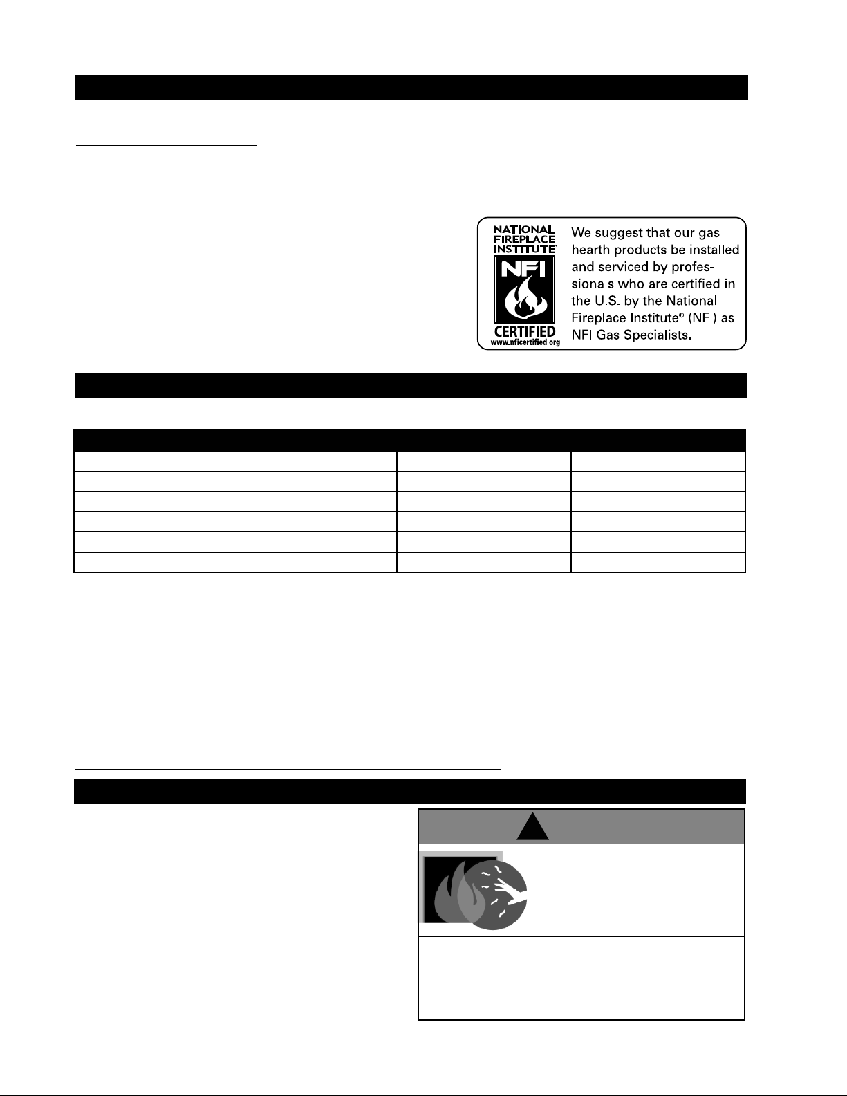
RATES AND EFFICIENCIES
NATURAL GAS PROPANE GAS
Altitude 0 - 4,500* 0 - 4,500*
Maximum Input 6,000 6,000
Minimum Inlet Gas Supply Pressure 4.5” Water Column 11” Water Column
Maximum Inlet Gas Supply Pressure 7” Water Column 13” Water Column
Manifold Pressure Under Flow Conditions 3.5” Water Column 10” Water Column
* When the appliance is installed at elevations above 4,500ft, and in the absence of specifi c recommendations from
the local authority having jurisdiction, the certifi ed high altitude input rating shall be reduced at the rate of 4% for
each additional 1,000ft.
This appliance is only for use with the type of gas indicated on the rating plate. This appliance is not convertible
for use with other gases, unless a certifi ed kit is used.
Expansion / contraction noises during heating up and cooling down cycles are normal and are to be expected.
Purge all gas lines with the glass door of the appliance removed. Assure that a continuous gas fl ow is at the burner
before replacing the door.
Objects placed in front of the appliance must be kept a minimum of 48” from the front face of the unit.
Use only authorized accessories designed for and listed with the model.
CARE OF GLASS AND PLATED PARTS
The glass is 3/16” tempered glass, available from your
authorized dealer. Clean the glass after the fi rst 10 hours of
operation with a recommended gas appliance glass cleaner.
Thereafter clean as required. DO NOT CLEAN GLASS WHEN
HOT! Do not use abrasive cleaners to clean plated parts.
Buff lightly with a clean dry cloth. If the glass is not kept clean
permanent discolouration and / or blemishes may result.
DO NOT SUBSTITUTE MATERIALS. USE CARE WHEN
HANDLING GLASS COMPONENTS. DO NOT STRIKE,
OR SLAM SHUT. DO NOT OPERATE WITH BROKEN
!
WARNING
HOT GLASS
WILL CAUSE BURNS.
DO NOT TOUCH
GLASS UNTIL COOLED.
ALLOW CHILDREN TO TOUCH GLASS.
GLASS.
NEVER
W415-0689 / 06.25.08
Page 5
49
5
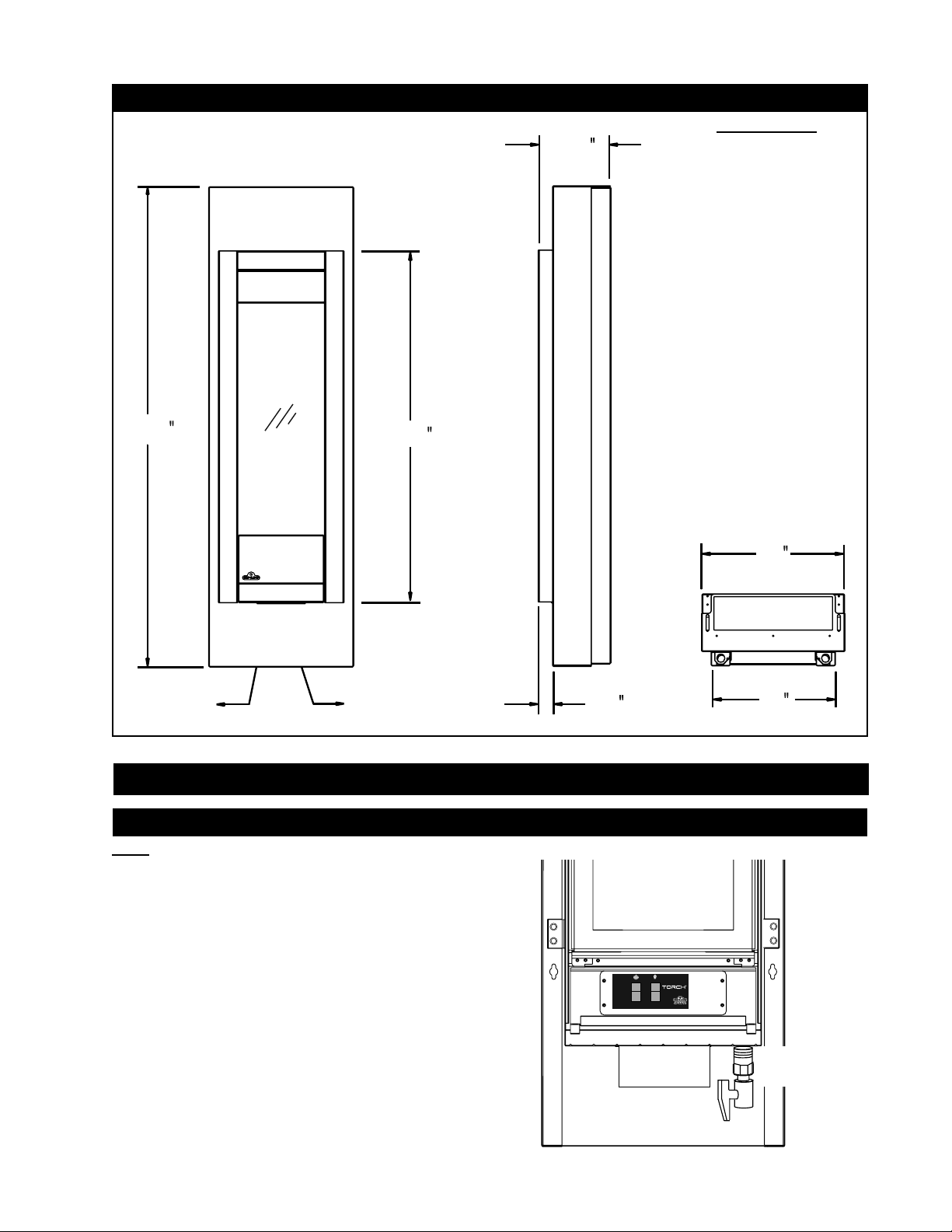
DIMENSIONS
FIGURES 1a-c
9
/
16
7
11
/
16
36
3
/
8
ELECTRICAL
ACCESS
GAS LINE
ACCESS
INSTALLATION
GAS INSTALLATION
Note: All gas connections must be contained within the
appliance when complete.
1. The appliance is designed to accept a 1/2” gas supply line. The
appliance is equipped with a 1/2” manual shut-off valve.
2. The access to the gas inlet is located in the bottom of the
cabinet.
3. The shut off valve / fl ex connector assembly must always be
contained within the cabinet.
15
1
/
2
1
W385-0380
13
4. When fl exing any gas line, support the gas valve so that the
lines are not kinked.
5. Check for gas leaks by brushing on a soap and water
solution.
FLEX
CONNECTOR
SHUT OFF
VALVE
W415-0689 / 06.25.08
Page 6

6
R
ELECTRICAL CONNECTION
!
WARNING
RISK OF ELECTRIC SHOCK!
Control and valve operate with 110v.
Do NOT use the appliance if any part has been
under water. Call a qualifi ed service technician
IMMEDIATELY to have the appliance inspected
for damage to the electrical circuit.
HARD WIRING CONNECTION
IT IS NECESSARY TO HARD WIRE THIS
APPLIANCE.
This appliance must be electrically connected and
grounded in accordance with local codes. In the
absence of local codes, use the current CSA C22.1
CANADIAN ELECTRICAL CODE in Canada or the
ANSI/NFPA 70-1996 NATIONAL ELECTRICAL
CODE in the United States.
NOTE: During assembly, anti-oxidant
compound was applied to all electrical
connections. If replacing the existing wire
harness or disconnecting any connectors, it is
highly recommended to re-apply anti-oxidant
compound to the relative connections.
FIGURE 3
IGNITOR
IGNITOR
WIRE
CONTROL MODULE
Illustration for reference only.
Follow the complete installation
instructions included with the GFI.
110v
POWER
SUPPLY
(Ground Fault Interrupter)
G
R
O
U
N
D
GFI
YELLOW
VALV E
BROWN
W
H
I
T
E
GAS
B
L
A
C
K
12
TEST
RESET
4
3
SWITCH
CLEARANCES TO COMBUSTIBLES
!
WARNING
The GSST8 is designed for outdoor application
only. The unit must be installed in the cabinet
provided. The cabinet is designed to be installed
on fi nished surfaces.
The GSST8 can be recessed into a structure a
maximum of 12” provided that all clearances
are maintained.
The GSST8 cabinet may be installed directly
onto a combustible surface.
COMBUSTION AND VENTILLATION
AIR
This fi replace is intended for installation on an outdoor patio
or in your yard. It must never be installed inside the warm
air envelope of your structure.
It is highly recommended that this fi replaces be installed in a
“sheltered” area. Direct wind will cause an erratic fl ame and
possible pilot or main burner outage.
An erratic fl ame could also lead to excessive carboning
(black soot), this condition is not a safety issue but is visually
undesirable.
Typical installation may include covered patio, screened
porch, gazebo, or on an outside wall of a house.
MINIMUM CLEARANCES TO
COMBUSTIBLES:
- 18” to top
- 1” to sides
- 8” to bottom
- 0” to rear
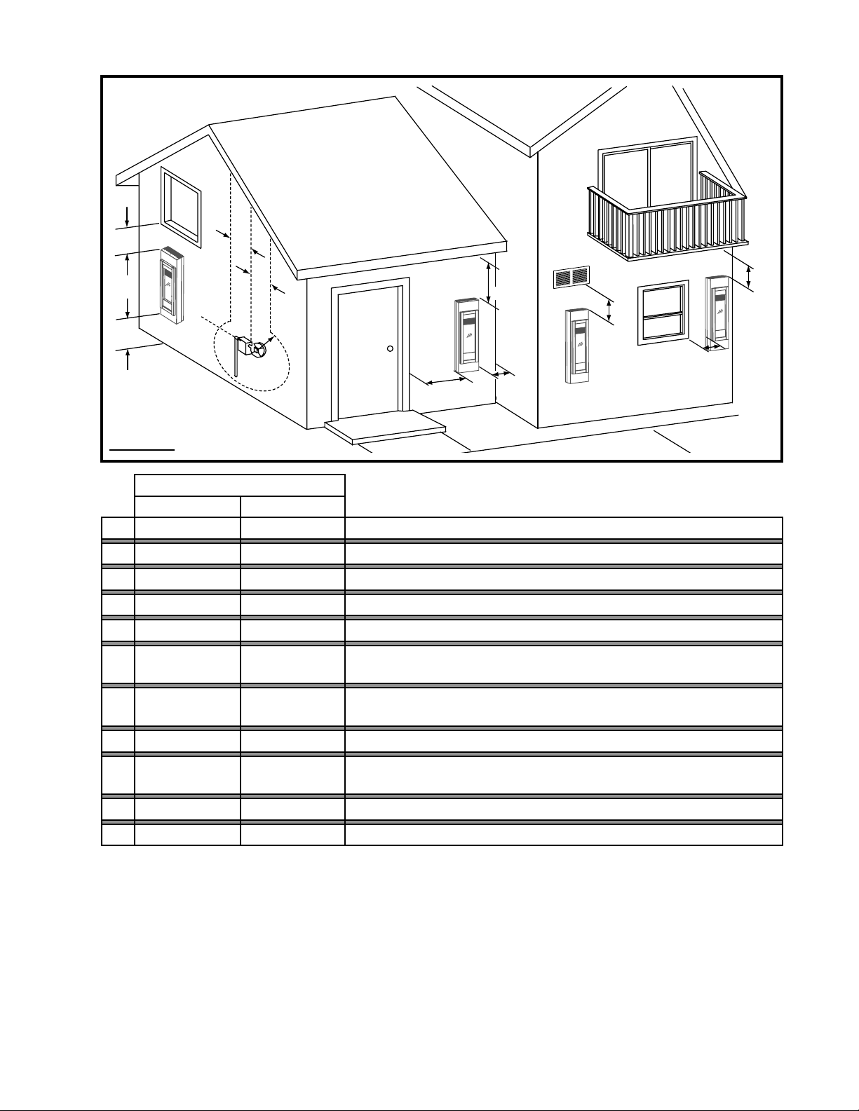
FIGURE 4
VENTILLATED
SOFFIT
18”
MIN.
OUTDOO
8”
MIN.
24”
MAX.
NOTE: Ensure the area has adequate ventilation.
W415-0689 / 06.25.08
Page 7
7
C
G
G
D
E
I
H
A
J
B
B
FIGURE 5
INSTALLATIONS
CANADA U.S.A.
A 8 INCHES 8 INCHES Clearance above grade, veranda porch, deck or balcony.
B 12 INCHES 9 INCHES Clearance to windows or doors that open.
C 12 INCHES* 12 INCHES* Clearance to permanently closed windows.
D 18 INCHES** 18 INCHES** Vertical clearance to ventilated soffi t.
E 12 INCHES** 12 INCHES** Vertical clearance to an unventilated soffi t.
F
K
F 1 INCH 1 INCH
G 3 FEET 3 FEET***
H 3 FEET 3 FEET*** Clearance to a service regulator vent outlet.
I 12 INCHES 9 INCHES
J 6 FEET 3 FEET**** Clearance to a mechanical air supply inlet.
K 12 INCHES† 12 INCHES*** Clearance under a veranda, porch, deck or balcony.
* Recommended to prevent condensation on windows and thermal breakage.
** It is recommended to use a heat shield and to maximize the distance to vinyl clad soffi ts.
*** This is a recommended distance. For additional requirements check local codes.
**** Three feet above if within 10 feet horizontally.
† Permitted only if the veranda, porch, or deck is fully open on a minimum of two sides beneath the fl oor.
Clearance to an inside combustible corner wall or protruding
combustible obstructions. (vent chase, etc.)
Clearance to each side of the centre line extended above the metre/
regulator assembly to a maximum vertical distance of 15 ft.
Clearance to a non-mechanical air supply inlet to the building or a
combustion air inlet to any other appliance.
W415-0689 / 06.25.08
Page 8

8
FINISHING
TMCSS MOUNTING CABINET INSTALLATION
!
WARNING
Before starting the installation remove the
protective layer from all three components that
make up the GSST8 (cabinet, frame, and Torch)
NOTE: It is recommended that all fasteners be
stainless steel.
1. Using the installation template (W122-0401) supplied,
determine the best mounting location for your new Torch.
(refer to your manual for clearances) Mark all 14 hole
centres on the wall (surface) using the template.
2. Remove the template. Depending on the surface and
fasteners, drill the appropriate holes. Hold the Torch up,
aligning the mounting brackets to the mounting holes.
Secure the Torch to the wall using the appropriate
fasteners. NOTE: The Torch has been designed to
have a 1/2” clearance between the rear outer panel
and the mounting surface.
3. Start the fasteners into each of the six remaining
mounting holes. Align the keyholes of the frame to the
heads of the fasteners and slide the frame down onto the
fasteners. Ensure the frame is plumb and level before
tightening the fasteners. NOTE: It is recommended that
the gas and electrical be connected to the appliance
at this stage. Both must enter the appliance at the
opening created between the bottom of the Torch
and the bottom of the mounting frame.
4. Slide the front of the cabinet over the mounting
frame, ensuring the “mesh” is to the top. Start each of
the four screws (supplied) through the slots. Once the
cabinet has been adjusted for depth the
four screws can be tightened.
1
CABINET
FIGURE 6
INSTALLATION
TEMPLATE
TORCH
MOUNTING
FRAME
4
3
W415-0689 / 06.25.08
2
MOUNTING
BRACKET
KEYHOLE
Page 9

RAIN TABS
When shipped, the rain tabs should be at a 90º angle. Push
the rain tabs down until they are at an approximate 60º angle to
assist rain in running off and out of the unit.
DOOR REMOVAL
FIGURE 9
E
G
N
A
L
F
R
O
O
D
P
O
T
9
90º
0º
6
The door is held in place at the bottom by a retainer tab
that inserts into a slot in the bottom edge of the door, and
at the top with a tab that secures in the same fashion. The
door is removed by lifting it off the tabs. When replacing,
guide the door over the upper tab fi rst, then over the lower
tab.
SECURING THE DOOR IN PLACE
When shipped, the door is secured with two hitch pins
along the top edge, replacing them is optional.
To secure the door in place use the supplied hitch pins as
illustrated.
RAIN
TAB
FIGURE 8
E
T
R
A
R
O
O
D
M
O
T
T
O
B
I
N
E
R
GLASS REMOVAL
Having removed the door, lay on a smooth fl at surface, face down.
There are 4 glass retainers that need to be bent away from the
glass to release it from the frame. Do not pry on the glass.
When replacing DO NOT SUBSTITUTE MATERIAL, replace the
gasket (W562-0008) and the glass (W300-0110). Set new glass
into the frame and gently bend tabs into the gasket to secure.
* Ensure that the gasketed end of the glass is placed into the top of
the door frame.
NOTE: Care must be taken when removing and disposing of any
broken glass or damaged components. Be sure to vacuum up
any broken glass from inside the appliance before operation.
HITCH PIN
FIGURE 10
GASKET*
GLASS
TOP
GLASS
RETAINERS
FIGURE 11
W415-0689 / 06.25.08
Page 10

10
SLOT
FRAME
(REAR VIEW)
TRIM
BRACKET
TFSSO FRAME INSTALLATION
1.
Hang the frame onto the fi rebox by engaging the
top trim bracket into the slot in the top of the frame
and the bottom hooks of the frame into the slot in
the mounting cabinet.
FIGURE 12
TRIM
BRACKET
2. Install the trim bracket supplied in your manual
baggie to the fi rebox using 3 screws.
FIGURE 13
DOOR
CHAIN
NOTE: If the frame needs to be secured, use two screws
in the holes provided behind the control door.
Insert the door stop chain into the receiving slot in the control
door. Then insert the door chain into the receiving slot in
the frame so that when fully opened the control door has a
clearance of 1/8" to the mounting cabinet.
NOTE: In most cases a count of 15 balls on the chain
between receiving slots will be suffi cient.
FIGURE 14
LOGO PLACEMENT
With the control door closed, affi x the logo to the front face of the control
door at the bottom left corner.
CONTROL
DOOR
1/4”
(APPROX.)
W415-0689 / 06.25.08
FIGURE 15
1/4”
(APPROX.)
Page 11
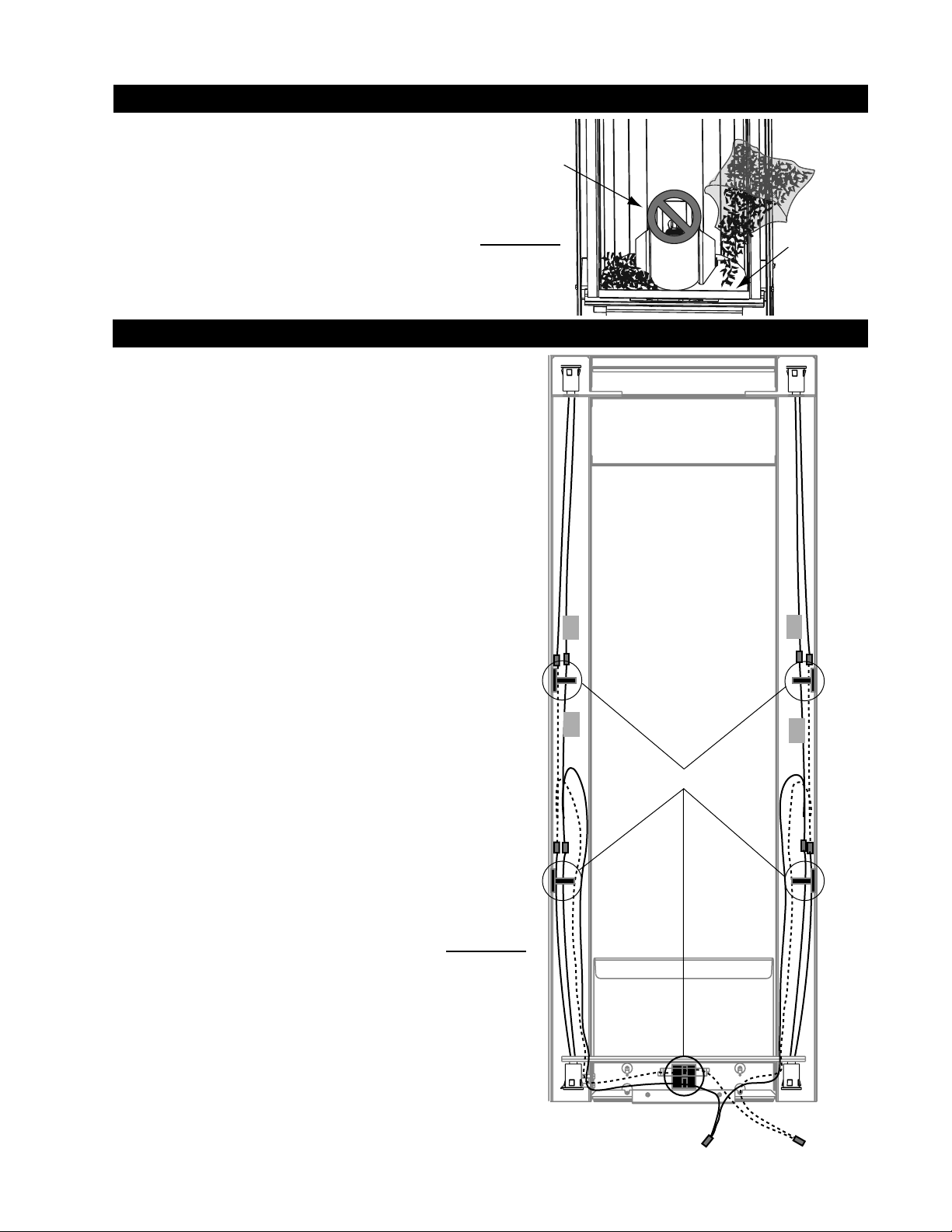
ACCENT GLASS INSTALLATION
Carefully sprinkle the accent glass onto the glass support
evenly. Ensure no glass falls into the burner area. If this
happens, insert a clean bag into your vacuum cleaner and
vacuum out the accent glass. Replacement accent glass
can be purchased from your authorized dealer.
BURNER
11
ACCENT
GLASS
FIGURE 16
LK8 LIGHT INSTALLATION (OPTIONAL)
1. Turn off the electrical and gas supply to the appliance.
2. Remove the frame from the unit by removing the the 2 stainless
steel hex head securing screws from the bottom and lifting the
frame off of the top trim bracket.
3. Lay the frame down on its front, being careful not to scratch the
fi nish.
4. Starting at the top of the frame, take one light assembly and
carefully snap it into place in the hole provided. Repeat for each of
the light assemblies. The wires on the top 2 light assemblies will
need to be fed in behind the heat shields.
Note: When installing the light kit be careful not to scratch
your fi ngers on any of the exposed screws in the frame.
5. Connect the light assemblies to the appropriate fl ags on the wire
harness. The wire harness is labeled (TR) top right, (BR) bottom
right (TL) Top left and (BL) bottom left.
6. Secure the wires into the clips at both sides and the bottom of the
frame. Use the extra clips provided to retain any loose wires.
7. Re-attach frame onto unit.
8. Open the control panel door, leave the wires connected to the
ON/OFF switch and place the transformer into the bottom of the
unit. Plug the transformer into the receptacle.
9. Attach one of the wire leads from the transformer to the lead on
the wire harness labeled “TRANS”, and the other to the ON/OFF
switch. Attach the last lead on the wire harness labeled “SWI” to
the ON/OFF switch.
10. Close the control panel door.
11. Turn on the gas supply and electrical power.
TL
BL
GLASS
SUPPORT
TR
BR
CLIPS X 5
FIGURE 17
SWI
TRANS
W415-0689 / 06.25.08
Page 12

12
OPERATING INSTRUCTIONS
If the appliance keeps shutting off, have it serviced. Keep
burner and control compartment clean.
When lit for the fi rst time, the fi replace will emit a slight
odour for a few hours. This is a normal temporary
condition caused by the curing “burn-in” of internal
paints and lubricants used in the manufacturing process
and will not occur again.
After extended periods of non-operation such as following
a vacation or a warm weather season, the fi replace may
emit a slight odour for a few hours. This is caused by
dust particles burning off.
Always shut off the fi replace, gas to the fi replace and
allow the fi replace to cool before servicing it.
FOR YOUR SAFETY READ BEFORE LIGHTING:
A. This appliance is equipped with an ignition device which
automatically lights the burner. Do not try to light by hand.
B. Before operating, smell all around the appliance area for
gas and next to the fl oor because some gas is heavier than
air and will settle on the fl oor.
C. Do not use this appliance if any part has been under water.
Immediately call a qualifi ed service technician to inspect the
appliance and replace any part of the control system and any
gas control which has been under water.
LIGHTING INSTRUCTIONS
1. STOP! Read the safety information located above.
2. Turn off all electric power to the appliance.
3. This appliance is equipped with an ignition device which
automatically lights the burner. Do not try to light by hand.
4. Remove the glass door.
5. Wait fi ve (5) minutes to clear out any gas. If you smell gas
including near the fl oor STOP! Follow “B” in the above safety
information on this label. If you don’t smell gas go to the next
step.
6. Replace the glass door.
TO TURN OFF GAS
1. Turn the appliance switch to the OFF position.
2. Turn off all electrical power to the appliance if service is to
be preformed.
WHAT TO DO IF YOU SMELL GAS:
• Turn off all gas to the appliance.
• Do not try to light any appliance.
• Do not touch any electrical switch; do not use a mobile or
land phone.
• Immediately call your gas supplier from a neighbor’s
phone. Follow the gas supplier’s instructions.
• If you cannot reach your gas supplier, call the fi re
department.
7. Turn on all electric power
to the appliance.
A
8. Turn the appliance
switch to the ON position.
9. If appliance will not
operate, follow instructions
“To Turn Off Gas” and call
your service technician or
gas supplier.
FIGURE 18
S
O
3. Turn manual shut-off valve clockwise to off.
Do not force.
RATING LABEL LOCATION:
The rating label is located under
the control panel and is chained to
the appliance.
DO NOT REMOVE.
W415-0689 / 06.25.08
RATING PLATE
R
T
E
E
T
K
N
I
CUS
W
a
r
n
o
c
REFERENCE
# W/N 16036
MINIMUM SUPPLY PRESSURE: 4.5" WATERCOLUMN
MAXIMUM SUPPLY PRESSURE: 7.0" WATERCOLUMN
WARNI NG: DO NOT ADD ANY MATERIAL TO THE
APPLIANCE, WHICH WILL COME IN CONTACT WITH THE
FLAMES, OTHER THAN THAT SUPPLIED BY THE
MANUFACTURER WITH THE APPLIANCE.
MINIMUM CLEARANCES TO COMBUSTIBLE MATERIALS
TOP 18” BACK 0”
SIDES 1” FLOOR 8”
TOP, SIDES & BACK AS PER ABOVE. FOR FINISHING
MATERIAL, SEE OWNERS MANUAL.
ELECTRICAL RATING: 115v 0.82AMP, 60HZ
CERTIFIED UNDER : CR97-003-M85, IAS US 4-96 OUTDOOR GAS FIREPLACE
IF APPLIANCE HAS BEEN SUPPLIED WITH A GAS PRESSURE REGULATOR, IT MUST BE USED. THE
GAS SUPPLY MUST BE TURNED OFF AT THE LP-GAS SUPPLY CYLINDER WHEN THIS APPLIANCE IS
CM
y
NOT IN USE. DO NOT STORE OR USE GASOLINE OR OTHER FLAMMABLE VAPORS AND LIQUIDS IN
e
s
r
e
H
k
THE VICINITY OF THIS OR ANY OTHER APPLIANCE. IMPROPER INSTALLATION, ADJUSTMENT,
ALTERATION, SERVICE OR MAINTENANCE CAN CAUSE INJURY OR PROPERTY DAMAGE. REFER TO
THE OWNER’S MANUAL PROVIDED WITH THIS APPLIANCE. FOR ASSISTANCE OR ADDITIONAL
INFORMATION, CONSULT A QUALIFIED INSTALLER, SERVICE AGENCY OR GAS SUPPLIER. MUST
NOT BE USED FOR COOKING. FOR OUTDOOR USE ONLY. IF STORED INDOORS, DETACH AND
LEAVE CYLINDER OUTDOORS.
MODEL
GSST8N
(NATURAL GAS)
0-4500FT (0-1370m)
6,000 BTU/h
MANIFOLD PRESSURE: 3.5" WATER COLUMN
#56
CERTIFIED FOR CANADA AND USA
ALTITUDE
INPUT
ORIFICE
SERIAL NUMBER:
MODEL
GSST8P
(PROPANE)
0-4500FT (0-1370m)
6,000 BTU/h
MANIFOLD PRESSURE:10" WATER COLUMN
MINIMUM SUPPLY PRESSURE: 11" WATER COLUMN
MAXIMUM SUPPLY PRESSURE: 13" WATER COLUMN
NOT FOR USE WITH SOLID FUEL. FOR USE WITH
GLASS DOOR. CERTIFIED WITH THIS UNIT ONLY.
THIS APPLIANCE IS ONLY FOR USE WITH THE TYPE
OF GAS INDICATED ON THE RATING PLATE. THIS
APPLIANCE IS NOT CONVERTIBLE FOR USE WITH
OTHER GASES, UNLESS A CERTIFIED KIT IS USED.
WOLF STEELLTD, BARRIE, ON, CANADA
MADE INCANADA
GSST8
#69
W385-0420
Page 13

MAINTENANCE
TURN OFF THE GAS AND ELECTRICAL POWER BEFORE
SERVICING THE APPLIANCE.
CAUTION: Label all wires prior to disconnection when
servicing controls. Wiring errors can cause improper and
dangerous operation. Verify proper operation after servicing.
This appliance should be inspected before use and at
least annually by a qualifi ed service person. The appliance
area must be kept clear and free of combustible materials,
gasoline or other fl ammable vapours and liquids. The fl ow of
combustion and ventilation air must not be obstructed.
1. Keep the control compartment, burner, and air shutter
opening clean by vacuuming or brushing, at least once a
year.
2. Check to see that the main burner ignites when the switch
for the burner is turned on. A 5 second light-up period is
satisfactory. If ignition takes longer, consult your authorized
dealer.
3. Check that the gasketing on the sides and top of the door
are not broken or missing. Replace if necessary.
13
CLEANING
• Visually inspect the appliance for carbon buildup.
• Using a small whisk or brush, brush off the excess carbon
and vacuum up or sweep into the garbage.
• Check the fi replace for corrosion of the main burner base.
Cleaning Stainless Steel: Do not use abrasive cleaners
to clean any painted, porcelain or stainless steel parts. To
clean stainless surfaces, use a stainless steel cleaner or a
non-abrasive cleaner. Always wipe in the direction of the grain.
Do not use steel wool, as it will scratch the fi nish. Stainless
steel parts will discolour when heated, usually to a golden or
brown colour. This discoloration is normal and will not affect
the performance of the fi replace.
GAS PRESSURE ADJUSTMENT
Outlet pressure can be
adjusted if not measuring
3.5” W.C. (NG) or 10.0”
W.C. (LP).
1. Pressure can be
checked by removing
cap (A) using
a 3/16 allen key and
replacing it with a 1/8
NPT barb fi tting.
2. Place pressure gauge
tube over the fi tting.
3. Pressure can be
adjusted by removing
cap (B) using a fl at
screwdriver, and
adjusting the nylon plug
with the same screw
driver. Turning the plug in
(clockwise) will increase
the pressure.
1/8
NPT BARB
FITTING
A
PRESSURE
GAUGE
ADJUSTMENTS
Closing the air shutter will cause
a more yellow fl ame, but can
lead to carboning. Opening the
air shutter will cause a more
blue fl ame, but can cause fl ame
lifting from the burner. The
flame may not appear yellow
immediately; allow 15 to 30
minutes for the fi nal fl ame color
to be established.
AIR SHUTTER OPENINGS
LP 3/16” DIA
NG 1/16” DIA
NOTE: It is important that the venturi sits down tight on
the orifi ce. The burner is adjustable up/down to ensure
this. The electrode sensors should be located 1/4” above
the burner for proper operation.
FLAME CHARACTERISTICS
It is important to periodically
perform a visual check of the
burner fl ame. Compare them to
the illustration provided.
3.5
1/8”
FIGURE 19
B
NATURAL
GAS
10
PROPANE
GAS
1/4”
VENTURI ADJUSTMENT
VENTURI
BURNER
AIR
FIGURE 21
FIGURE 22
SHUTTER
OPENING
ORIFICE
FIGURE 20
W415-0689 / 06.25.08
Page 14
14
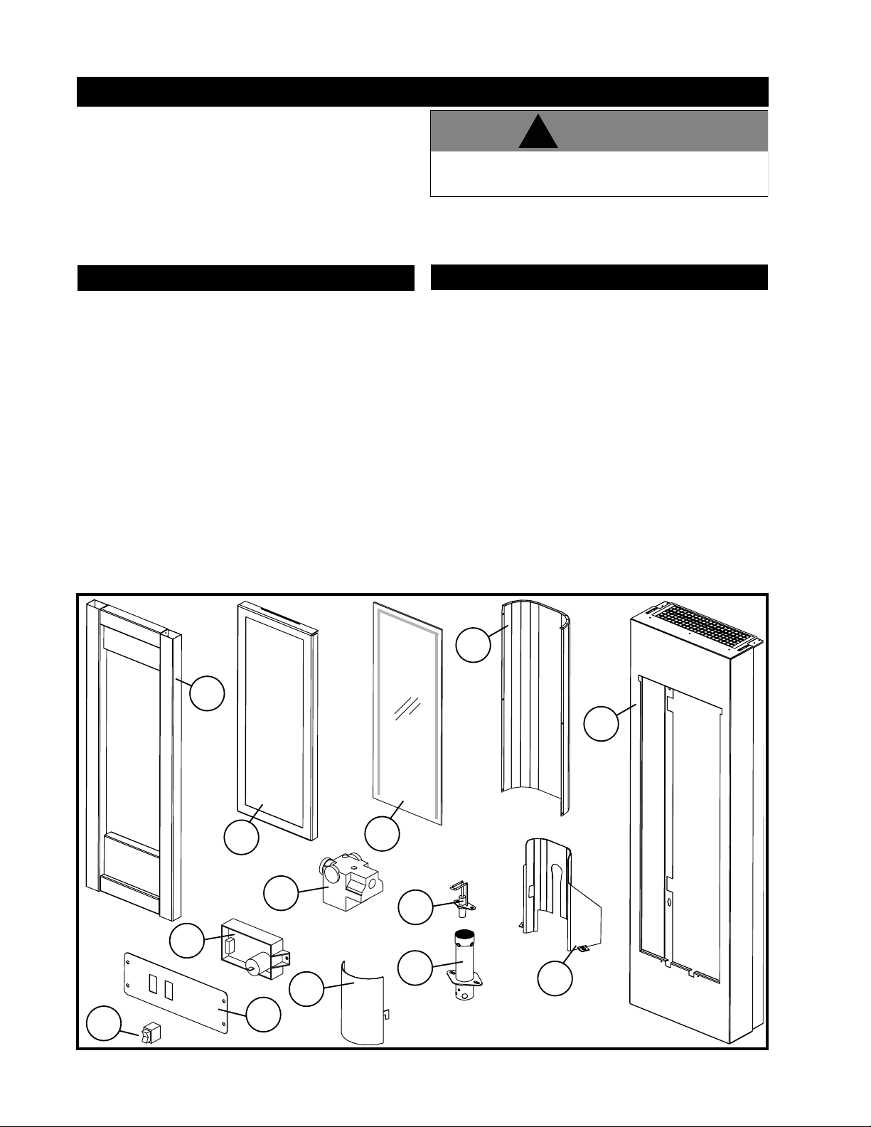
REPLACEMENTS
Contact your dealer for questions concerning prices and
availability of replacement parts. Normally all parts can be
ordered through your authorized dealer or distributor.
When ordering replacement parts always give the following
information:
1. MODEL & SERIAL NUMBER OF APPLIANCE
2. INSTALLATION DATE OF APPLIANCE
3. PART NUMBER
4. DESCRIPTION OF PART
5. FINISH
!
WARNING
Failure to position the parts in accordance with these diagrams or
failure to use only parts specified approved with this appliance may
FOR WARRANTY REPLACEMENT PARTS , A PHOTOCOPY OF THE ORIGINAL
INVOICE WILL BE REQUIRED TO HONOUR THE CLAIM.
*
IDENTIFIES ITEMS WHICH ARE NOT ILLUSTRATED. FOR FURTHER
INFORMATION, CONTACT YOUR AUTHORIZED DEALER.
result in property damage or personal injury.
REPLACEMENT PARTS
#
PART NO. DESCRIPTION
1 W225-0223 DOOR FRAME
2* W562-0008 DOOR GASKET
3 W010-1959 GLASS
4* W300-0110 GLASS
5 W100-0111 BURNER
6 W357-0006 IGNITOR
7 W190-0026 CONTROL, MODULE
8* W750-0202 WIRE HARNESS
9* W750-0184 IGNITION CABLE
10 W200-0263 IGNITOR COVER
11 W200-0262 BURNER COVER
12 W725-0052 NATURAL GAS VALVE - 3.5” W.C.
12 W725-0053 PROPANE GAS VALVE - 10.0” W.C.
13* W455-0085 #56 NATURAL GAS ORIFICE
13* W455-0086 #69 PROPANE GAS ORIFICE
14 W475-0590 BACK PANEL
15* W300-0108 ACCENT GLASS (
16* W385-0334 NAPOLEON® LOGO
17* W562-0046 ROPE GASKET, BACK PANEL
18 W475-0595 CONTROL PANEL
19* W385-0380 CONTROL PANEL LABEL
20 W660-0082 OUTDOOR ON/OFF SWITCH
C/W GASKET
BLACK)
ACCESSORIES
21 TMCSS MOUNTING CABINET
22 TFSSO FRAME KIT
23* LK8 LIGHT KIT
24* W573-0002 HIGH TEMPERATURE SEALANT
25* W573-0007 HIGH TEMPERATURE SEALANT
26* W175-0270 CONVERSION KIT 27* W175-0274 CONVERSION KIT - LP TO NG
NG TO LP
14
20
W415-0689 / 06.25.08
7
21
1
12
18
11
3
6
5
21
10
Items not shown to scale.
Page 15
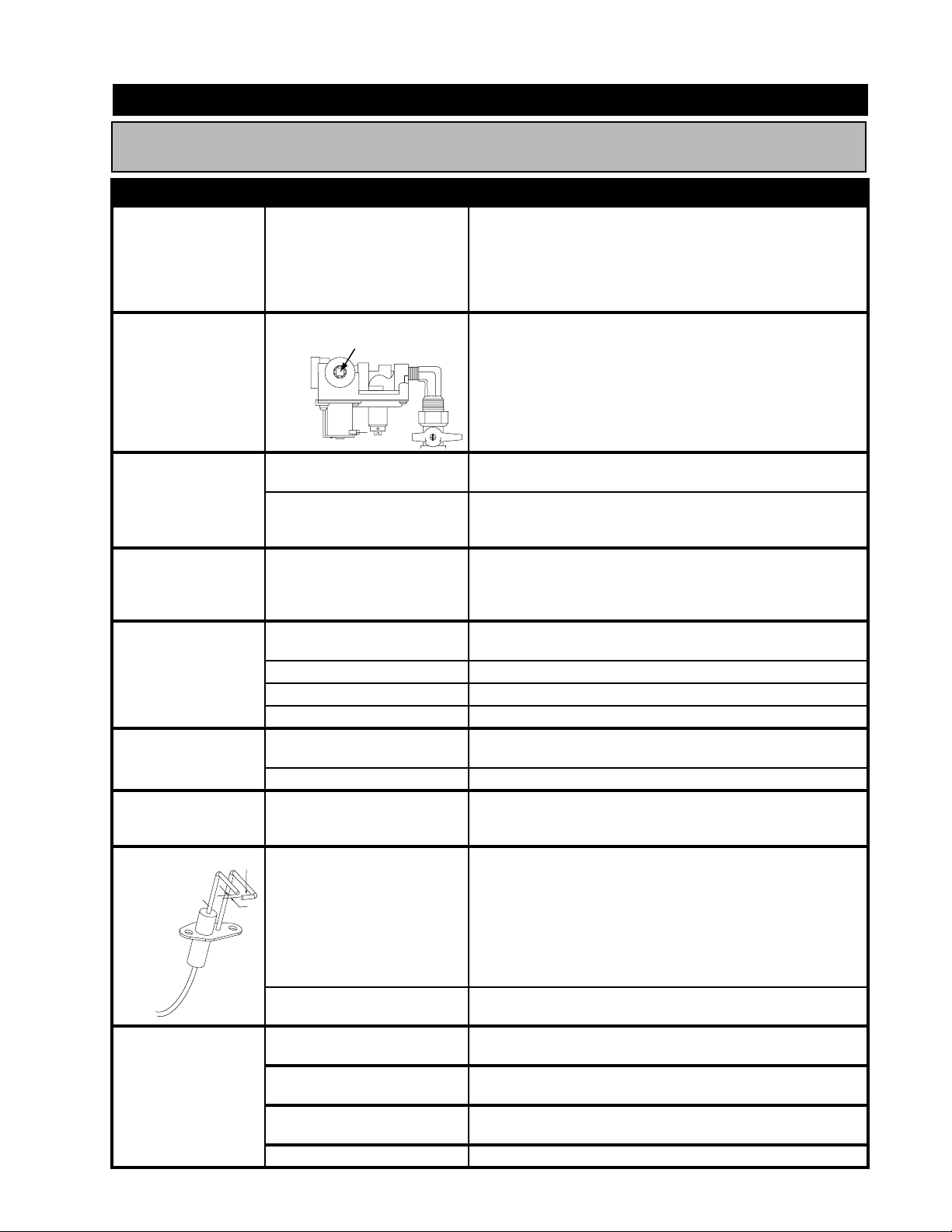
TROUBLE SHOOTING GUIDE
BEFORE ATTEMPTING TO TROUBLESHOOT, PURGE YOUR UNIT AND INITIALLY LIGHT
THE IGNITOR AND THE MAIN BURNER WITH THE GLASS DOOR REMOVED.
SYMPTOM PROBLEM TEST SOLUTION
Electrode sparks,
burner ignites,
electrode continues
to spark for
complete 7 seconds,
burner shuts down.
Flame length
consistently too
large or too small.
Carboning occurs.
Carbon is being
deposited on glass,
and combustion
chamber surfaces.
White / grey fi lm
forms.
No gas to the main
burner; switch is on.
Burner will not light,
ignitor sparks.
Electrode does not
spark. Burner does
not light.
Ignitor
will
not
ELECTRODE
spark.
HIGH
VOLTAGE
IGNITION
CABLE
CERAMIC
BODY
Remote wall switch
is in “OFF” position;
burner comes on.
Hot and neutral wires are
reversed at control module.
Sensor / fl ame not
connecting
Unit is over-fi red or under-
fi red.
A
- Connect the hot wire to the black wire. Connect the neutral
wire to the white wire.
- Raise electrode / sensor up into fl ame 1/4” above the burner.
- Check pressure readings
- Outlet pressure can be checked by removing cap (A) and
replacing it with a 1/8” NPT barb fi tting. Next, place pressure
gauge tubing over the fi tting. Gauge should read 3.5” W.C.
for natural gas or 10.0” W.C. for propane. AFTER TAKING
PRESSURE READINGS, BE SURE TO REPLACE CAP TO
RESEAL. DO NOT OVER-TORQUE.
S
O
Air shutter has become
blocked.
Flame is impinging on the
combustion chamber.
Sulphur from fuel is being
deposited on glass, logs
or combustion chamber
surfaces.
Switch is defective.
- Leak test with a soap and water solution.
- Ensure air shutter opening is free of lint or other obstructions.
- Open air shutter to increase the primary air.
- Check the input rate: check the manifold pressure and orifi ce
size as specifi ed by the rating plate values.
- Clean the glass with a gas appliance glass cleaner. DO NOT
CLEAN GLASS WHEN HOT. If deposits are not cleaned off
regularly, the glass may become permanently marked.
- Connect a jumper wire across the wall switch terminals; if main
burner lights, replace switch.
Burner orifi ce is blocked. - Remove stoppage in orifi ce.
Control valve faulty. - Replace.
Faulty valve. - Replace.
No gas at the burner.
- Check that the manual valve is turned on.
- Replace the valve.
Out of propane gas. - Fill the tank.
GFCI has been tripped. - Push reset button (red) on the face of the GFCI.
SENSOR
1
/8”
GAP
No spark at ignitor.
- Check the power source. (ie. fuse, circuit breaker, GFCI resent
button.)
- Check that the wire is connected to both the ignitor and the
control module.
- Check that the spark is not jumping to ignitor cover.
- Replace the wire if the wire insulation is broken or frayed.
- Replace the electrode if the ceramic insulator is cracked or
broken.
Spark gap is incorrect.
Wall switch is mounted
upside down.
Remote wall switch is
grounding.
Remote wall switch wire is
grounding.
- Spark gap should be 0.125” (1/8” approx.) from the electrode
tip to the sensor tip.
- Reverse.
- Replace.
- Check for ground (short); repair ground or replace wire.
Faulty wire. - Replace.
W415-0689 / 06.25.08
15
Page 16

16
SPECIAL CONCERNS
SERVICE PERFORMANCE
Fireplace Service History
SERVICE TECHNICIAN NAME
This fireplace must be serviced annually depending on usage
DEALER NAME
W415-0689 / 06.25.08
DATE
 Loading...