

Page 1
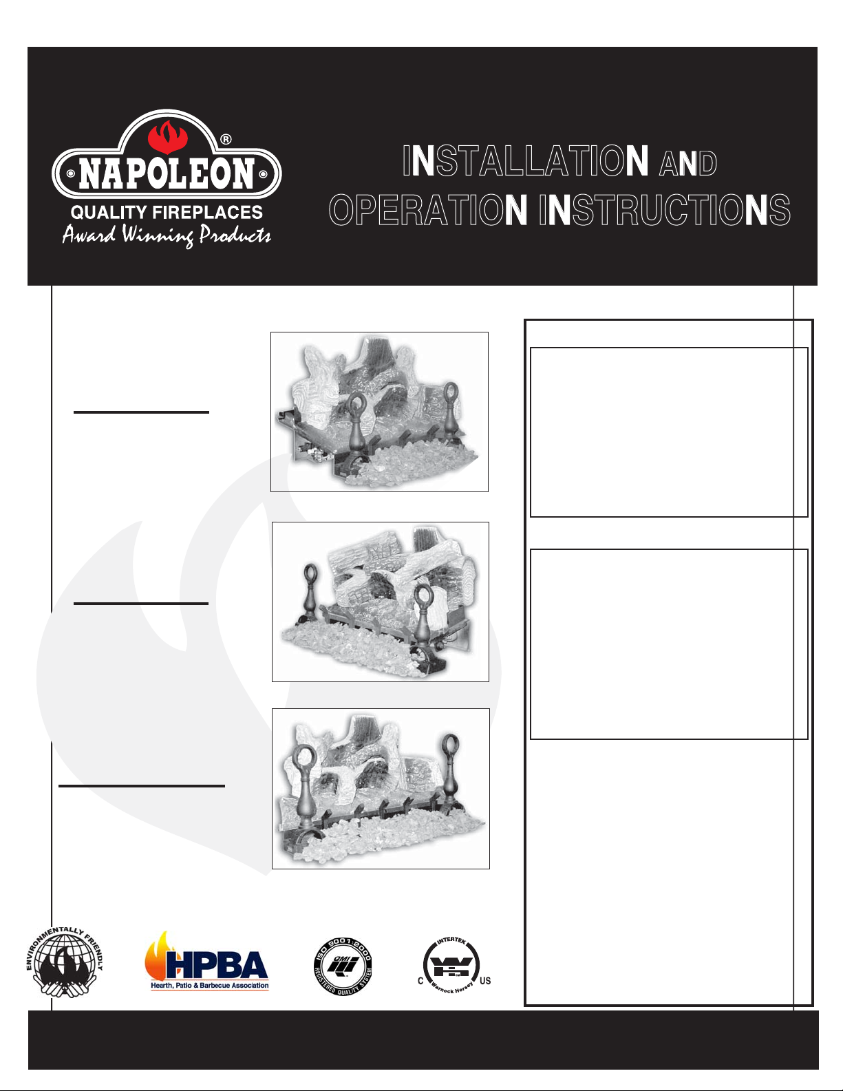
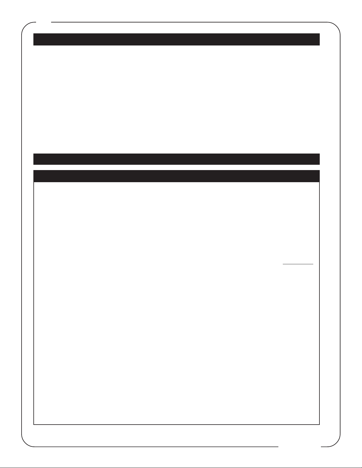
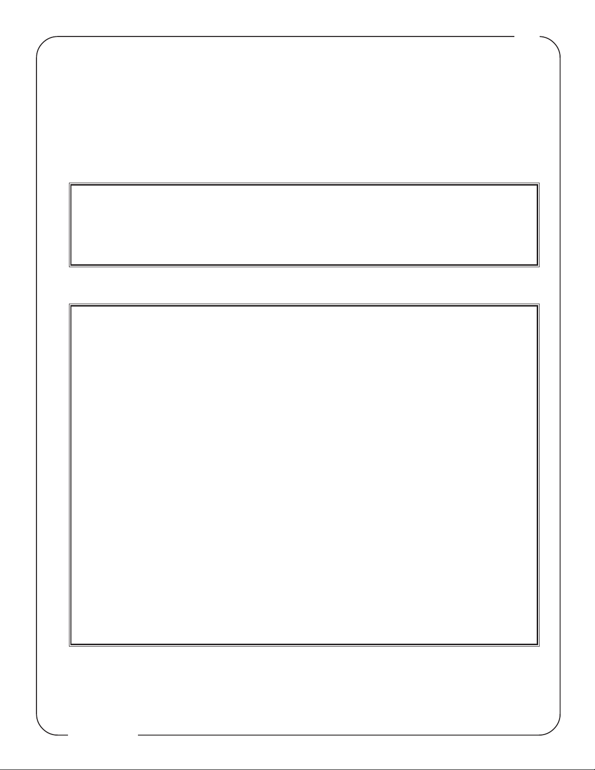
These log sets can be installed in vented or unvented applications. See installation details for the particular application that applies.
INSTALLER: THESE INSTRUCTIONS MUST BE CONVEYED TO AND REMAIN WITH THE HOMEOWNER.
1
INSTALLATION AND
OPERATION INSTRUCTIONS
CERTIFIED UNDER: ANSI Z21.11.2B-2004 GAS FIRED ROOM HEATER : VOLUME II, UNVENTED ROOM HEATERS AND
ANSI Z21.60-2002 / CSA 2.26-2002 DECORATIVE GAS APPLIANCES FOR INSTALLATION IN SOLID-FUEL BURNING APPLIANCES
WARNING
If the information in this manual is
GVFL18N
NATURAL GAS
GVFL18P
PROPANE
not followed exactly, a fire or
explosion may result causing property
damage, personal injury or loss of
life.
Do not store or use gasoline or other
flammable vapors and liquids in the
vicinity of this or any other appliance.
GVFL24N
NATURAL GAS
GVFL24P
PROPANE
GVFL30N
NATURAL GAS
GVFL30P
PROPANE
WHAT TO DO IF YOU SMELL GAS
• Do not try to light any appliance.
• Do not touch any electrical
switch; do not use any phone in
your building.
• Immediately call the gas supplier
from a neighbour's phone. Follow
the gas supplier's instructions.
• If you cannot reach your gas
supplier, call the fire department.
Installation and service must be
performed by a qualified installer,
service agency or the gas supplier.
If this unit is used as an unvented
gas-fired heater, it uses air (oxygen)
from the room in which it is installed.
Provisions for adequate combustion
and ventilation air must be provided.
Refer to "Installing in an unvented
application" section in this manual.
IMPORTANT: Read these instructions
carefully before trying to operate this
vent-free gas heater.
Wolf Steel Ltd., 24 Napoleon Rd., Barrie, ON L4M 4Y8 Canada • (705)721-1212 • fax(705)722-6031
W415-0530 / 12.14.05
www.napoleonfireplaces.com • ask@napoleon.on.ca
Page 2
2
TABLE OF CONTENTS
2 Warnings
3 Warranty
4-5 General Instructions
General Information
Maintenance and Cleaning
Air Shutter
Minimum Fireplace Size
Andiron and Grate Assembly
Gas Piping
6-7 Installing In An Unvented Application
Combustion and Ventilation
Determining Confined or Unconfined
Space
PLEASE RETAIN THIS MANUAL FOR FUTURE REFERENCE
WARNINGS
• Due to high temperatures, the appliance should be
located out of traffic and away from furniture and
draperies.
• Children and adults should be alerted to the
hazard of high surface temperatures and should
stay away to avoid burns or clothing ignition.
• Young children should be carefully supervised when
they are in the same room with the appliance.
• Do not place clothing or other flammable material
on or near the appliance.
• Any safety screen or guard removed for servicing
an appliance must be replaced prior to operating
the heater.
• Installation and repair should be done by a qualified service person. The appliance should be inspected before use and at least annually by a professional service person. More frequent cleaning
may be required due to excessive lint from carpeting, bedding material, etc. It is imperative that control compartments, burners and circulating air passageways of the appliance be kept clean.
• Any change to this heater or it’s controls can be
dangerous.
• The fireplace and gas logs function as a system. If
the fireplace is not drafting properly and spilling into
the room (check with a match or a smoke stick),
reposition the damper clamp until a positive draft
is obtained by opening the damper. If negative
pressure in home prevents having a positive draft,
consult an air quality specialist.
• The gas log heater must be secured to the
fireplace floor to ensure that the position is
not changed while adjusting the controls.
• Sooting and an improper burn may result
from shifting of the gas logs by moving the
unit. A gas leak could be caused by moving
the grate.
7 Installing In A Vented Application
Damper Stop Installation
8-9 Operating / Maintenance
Operating Instructions
Lighting Instructions
ODS Pilot Cleaning
Match Lighting Instructions
10 Log Placement
Logo Placement
11 Finishing
Rating Plate
12 Replacement Parts
Accessories
• If you are installing the unit into a sunken
fireplace, you must raise the fireplace floor
to allow access to the gas log controls.
Raising the floor ensures adequate air flow
and guards against sooting. The fireplace
floor must be raised using noncombustible
materials.
• This appliance is for installation only in a
solid-fuel burning masonary or UL 127
factory-built fireplace or in a listed ventless
firebox enclosure. It has been design
certified for these installations. Exception:
DO NOT install this appliance in a factorybuilt fireplace that includes instructions
stating it has not been tested or should not
be used with unvented gas logs.
• This appliance is only for use with the type
of gas indicated on the rating plate. This
appliance is not convertible for use with
other gases.
• A fireplace screen must be in place when
the appliance is operating and, unless other
provisions for combustion air are provided,
the screen shall have an opening for
introduction of combustion air.
• Any glass doors shall be completely opened
when the appliance is in operation.
• State or local codes may only allow operation
of this appliance in a vented configuration.
Check your state or local codes.
• Do not use a blower insert, heat exchanger
insert or any other accessory not approved
for use with this appliance.
W415-0530 / 12.14.05
Page 3
NAPOLEON products are manufactured under the strict Standard of the world recognized ISO
9001:2000 Quality Assurance Certificate.
NAPOLEON products are designed with superior components and materials, assembled by trained crafts-
men who take great pride in their work. Once assembled the complete log set is thoroughly inspected by a
qualified technician before packaging to ensure that you, the customer, receive the quality product that you
expect from NAPOLEON.
NAPOLEON GAS LOG SET LIMITED WARRANTY
The Phazer™ logs in your new Napoleon gas log set are warranted against defects for as long as you own the
appliance.
Electrical (millivolt) components, burner and wearable parts such as the gas valve, thermal switch, switches,
wiring, remote control, ignitor, gasketing, and pilot assembly are covered and NAPOLEON will provide
replacement parts free of charge during the first year of the limited warranty.
CONDITIONS AND LIMITATIONS
NAPOLEON warrants its products against manufacturing defects to the original purchaser only -- i.e., the individual
or legal entity (registered customer) whose name appears on the warranty registration card filed with NAPOLEON
-- provided that the purchase was made through an authorized NAPOLEON dealer and is subject to the following
conditions and limitations:
This factory warranty is nontransferable and may not be extended whatsoever by any of our representatives.
Installation must be done in accordance with the installation instructions included with the product and all local and
national building and fire codes.
This limited warranty does not cover damages caused by misuse, lack of maintenance, accident, alterations, abuse
or neglect and parts installed from other manufacturers will nullify this warranty.
This limited warranty further does not cover any scratches, dents, corrosion or discolouring caused by excessive
heat, abrasive and chemical cleaners, mechanical breakage of PHAZER™ logs and embers.
In the first year only, this warranty extends to the repair or replacement of warranted parts which are defective in
material or workmanship provided that the product has been operated in accordance with the operation instructions
and under normal conditions.
Napoleon will not be responsible for installation, labour or any other expenses related to the reinstallation of a warranted part and such expenses are not covered by this warranty.
Notwithstanding any provisions contained in this Limited Warranty, NAPOLEON’S responsibility under this warranty
is defined as above and it shall not in any event extend to any incidental, consequential or indirect damages.
This warranty defines the obligations and liability of NAPOLEON with respect to the NAPOLEON gas logs and any
other warranties expressed or implied with respect to this product, its components or accessories are excluded.
Napoleon neither assumes, nor authorizes any third party to assume, on it's behalf, any other liabilities with respect
to the sale of the product.
Any damages to burner and logs or other components due to water, weather damage, long periods of dampness,
condensation, damaging chemicals or cleaners will not be the responsibility of NAPOLEON.
The bill of sale or copy will be required together with a serial number and a model number when making any warranty
claims from your authorized dealer. The warranty registration card must be returned within fourteen days to register
the warranty.
NAPOLEON reserves the right to have its representative inspect any product or part thereof prior to honouring any
warranty claim.
3
ALL SPECIFICATIONS AND DESIGNS ARE SUBJECT TO CHANGE WITHOUT PRIOR NOTICE DUE TO ON-GOING
PRODUCT IMPROVEMENTS. NAPOLEON® IS A REGISTERED TRADEMARK OF WOLF STEEL LTD. PATENTS
U.S. 5.303.693.801 - CAN. 2.073.411, 2.082.915. © WOLF STEEL LTD.
W415-0530 / 12.14.05
Page 4
4
GENERAL INSTRUCTIONS
Do not use this gas log set if any part has been under
water.
Call a qualified service technician to inspect the appliance
before operating.
Thoroughly clean the chimney, flue and fireplace before installing this appliance into it.
Do not burn solid fuels in any fireplace that is equipped with
this gas log set.
The installation of this appliance must conform with local
codes or in the absence of local codes, it must conform to
ANSI Z.223.1 or the CAN/CGA B149.
Do not operate appliance in the presence of gasoline or other
flammable liquids and vapours. Keep area clear of other
combustible materials.
Any guard or safety screen removed for servicing must be
replaced before the appliance is operated.
The appliance and its shut off must be disconnected from
the gas supply piping system before any pressure testing of
the system is done.
Installation practices vary from region to region and it is important to know the specifics that apply to your area,
for example: in Massachusetts State:
• The appliance off valve must be a “T” handle gas cock.
• The flexible connector must not be longer than 36 inches.
• The appliance is not approved for installation in a bedroom or
bathroom unless the unit is a direct vent sealed combustion
product.
• WARNING: This product must be installed by a licensed
plumber or gas fitter when installed within the commonwealth
of Massachusetts.
• Un-vented room heater shall be installed in accordance with
527 CMR 30.00 and 248 CMR 3.00 through 7.00.
• Sellers of un-vented propane or natural gas-fired space/room
heaters shall provide to each purchaser a copy of 527 CMR
30.00 upon the sale of the unit from
http://www.napoleonfireplaces.com/Webshare/i
nstallation_manuals/mass_requirements.pdf
• A carbon monoxide detector is required in all rooms containing
gas fired appliances.
MAINTENANCE & CLEANING
Always shut off the appliance, gas to the appliance and
allow the appliance to cool before servicing it.
Visually inspect the appliance for carbon buildup.
Using a small whisk or brush, brush off the excess carbon
and vacuum up or sweep into the garbage.
Check the appliance for broken logs and corrosion of the
main burner base.
GENERAL INFORMATION
FOR YOUR SATISFACTION, THIS FIREPLACE HAS BEEN
TEST-FIRED TO ASSURE ITS OPERATION AND QUALITY! Maximum input is 40,000 BTU/hr for natural gas and
propane.
Minimum inlet gas supply pressure is 4.5 inches water col-
umn for natural gas and 11 inches water column for propane. Maximum inlet gas pressure is 7 inches water column
for natural gas and 13 inches water column for propane.
Manifold pressure under flow conditions is 3.5 inches water
column for natural gas and 10 inches water column for propane.
No external electricity (110 volts or 24 volts) is required
for the gas system operation.
This heater is equipped with a pilot light safety
system referred to as an
OXYGEN DEPLETION
SENSOR and is designed to turn off the heater
if not enough fresh air is available.
Use only accessories designed for and
listed with your specific fireplace.
Not designed for use with a glass door.
Screen must be closed when appliance is
in operation.
CARBON MONOXIDE POISONING
MAY LEAD TO DEATH
Early signs of carbon monoxide poisoning resemble the flu, with headache, dizziness and/
or nausea. If you have these signs, the heater
may not be working properly. Get fresh air at
once! Have heater serviced.
Some people---pregnant women, persons with
heart or lung disease, anaemia, those under
the influence of alcohol, those at high altitudes-
-- are more affected by carbon monoxide than
others.
W415-0530 / 12.14.05
Page 5

5
AIR SHUTTER
TESGOL RETTUHSRIA
LEUF
81LFVG
42LFVG
03LFVG
The air shutter settings are factory set for most installations.
However, adjustment may be required depending on fuel
type, vent performance and altitude.
Closing the air shutter will cause a more yellow flame, but
can lead to carboning. Opening the air shutter will cause a
more blue flame, but can cause flame lifting from the burner
ports. The flame may not appear yellow immediately; allow
15 to 30 minutes for the final flame colour to be established.
GN PL
9
/23"
9
/23"
9
/23"
5
5
5
/61"
/61"
/61"
MINIMUM FIREPLACE SIZE
Each gas log set must be installed into a fireplace cavity
with a minimum size.
Refer to the table below to determine the appropriate minimum fireplace size.
TESGOL THGIEH HTDIW HTPED
"81
81LFVG
"42
42LFVG
"81"22"41
"02"82"61
GAS PIPING
This appliance must be isolated from the gas supply piping system by closing the individual manual shut off valve
during any pressure testing of the gas supply piping system at test pressure equal to or less than ½ psi (3.5 kPa)
1. Centre the appliance in the fireplace opening, making
sure the appliance has enough room behind it for the gas
line to run behind the log set under the log support.
2. Route the gas line and sizing using piping ½” diameter
or greater to allow the full volume of gas to the appliance.
The routing of the gas line has to be done to local and / or
national codes.
3. When rigid pipe is used an ANSI approved manual shut
off and a union must be installed upstream within the fireplace cavity.
4. To ensure the appliance operates reliably install a sediment trap upstream of the appliance within the structures of
the piping system.
5. When using propane, a regulator must be used between
the tank and the outside wall of the house to ensure the line
pressure does not exceed 14” w.c.
6. Check gas connections with a gas detection device to
test for leaks in the system. Soapy water mixture can also
be used to check for leaks.
7. Once all the gas connections are tested for leaks, start
the appliance. Follow the lighting instructions to ensure
the appliance is working properly before finishing.
"03
03LFVG
"22"43"02
ANDIRON & GRATE ASSEMBLY
1. With the 2 andirons laying face down,
secure the grate overtop using 2x ¼-20
bolts (supplied in the manual baggie).
2. Install the grate/andiron assembly to the
burner base using 4x ¾” self tapping screws
(supplied in the manual baggie).
Use only accesso-
ries designed for and
listed with your
specific log set.
1
2
W415-0530 / 12.14.05
Page 6

6
INSTALLING IN AN UNVENTED APPLICATION
COMBUSTION & VENTILATION
AIR PROVISIONS
This heater shall not be installed in a confined space or
unusually tight construction unless provisions are provided for adequate combustion and ventilation air.
In order to avoid the possibility of exposed insulation or
vapour barrier coming in contact with the fireplace body,
it is recommended that the walls of the fireplace enclosure be 'finished', (i.e. drywall/sheetrock) as would any
other outside wall of the home. This will ensure that
clearance to combustibles is maintained within the cavity.
The National Fuel Gas Code, ANSI Z223.1 defines a con-
fined space as a space whose volume is less than 50 cubic
feet per 1,000 Btu per hour (4.8 m3 per kW) of the aggregate
input rating of all appliances installed in that space and an
unconfined space as a space whose volume is not less than
50 cubic feet per 1,000 Btu per hour (4.8 m
aggregate input rating of all appliances installed in that space.
Rooms communicating directly with the space in which the
appliances are installed, through openings not furnished with
doors are considered a part of the unconfined space.
3
per kW) of the
The GVFL18/24/30 are all rated at 40,000BTUs
per hour and therefore requires a minimum
unconfined space of 2,000 cubic feet.
ROOM 1
DETERMINING CONFINED OR UNCONFINED
SPACE
To determine the volume of the room where the heater is to
be installed, multiply the width x the length x the ceiling height
of that room measured in feet. If any adjoining rooms are
connected by grills or openings such as kitchen passthroughs, etc., the volume of those rooms may be added to
the total.
Multiply the room volume by 1000 and divide this amount by
50 to determine the maximum Btu/hr that the space can support with adequate combustion and ventilation air.
Add the Btu/hr of all fuel burning appliances located within
the space such as gas furnace, gas water heater, etc. Do
not include direct vent gas appliances which draw their input
and output air from and to the outdoors.
WARNING: If the area in which the heater may be oper-
ated is smaller than that defined as an unconfined space or
if the building is of unusually tight construction, provide adequate combustion and ventilation air by one of the methods described in the National Fuel Gas Code ANSI Z223.1,
Section 5.3 or the applicable local code.
ROOM 2
HEIGHT
If for example,
LENGTH
Room Volume = Length x Width x Height
Max BTU/hr = Room Volume x 1000 ÷ 50
EXAMPLE 1
In this example, because there is no door to the adjoining
room, the volume of the adjoining room may be added to the
volume of the room with the heater to get a total unconfined
space.
The total unconfined space: 800 + 1200 = 2000 cubic feet.
Maximum BTU/h:
If there are no more fuel burning appliances within this space
then the 30,000 BTU/h input of the fireplace is suitable to be
installed. This also assumes that the construction of this
space is not unusually tight.
2000 x 1000
50
= 40,000 BTU/h
WIDTH
The volume of Room 1: 10 x 10 x 8 = 800 cubic feet.
The volume of Room 2: 10 x 15 x 8 = 1200 cubic feet.
If in this example a solid door separates Room 1 from Room
2, the volume of Room 2 could not be used. In this case the
maximum BTU/h would be:
Maximum BTU/h:
This would be considered a confined space since it can not
support the 30,000BTU/h input of the heater and it would be
necessary to provide adequate combustion and ventilation
air to Room 1.
the length of the rooms is 10 feet,
the width of Room 1 is 10 feet,
the width of Room 2 is 15 feet
the height of the rooms is 8 feet.
EXAMPLE 2
800 x 1000
= 16,000 BTU/h
50
WARNING
Barriers such as the bottom of a glass door frame placed in front of a gas log set can change the air flow
characteristics of the fireplace which in turn can cause the unit to carbon or overheat and malfunction.
figure 1
W415-0530 / 12.14.05
Page 7

7
Unvented gas heaters are a supplemental zone
heater. They are not intended to be the primary
heating appliance.
Unvented gas heaters emit moisture into the
living area. In most homes of average construction, this does not pose a problem. In houses of
extremely tight construction, additional mechanical ventilation is recommended.
INSTALLING IN A VENTED APPLICATION
DAMPER STOP INSTALLATION
The damper must be permanately locked in position to
prevent full closure and to provide a minimum flue opening.
Various methods for locking the damper may be used but
may be restricted from region to region and it is important
to know the specifics that apply to your area. For your
convenience a damper stop is provided with the unit and
may be used where not prohibited by state or local codes.
Use the 3” adjustable bolt to adjust the damper to the correct
opening, based on the enclosed chart.
During manufacturing, fabricating and shipping
various components of this appliance are
treated with certain oils, films or bonding
agents.
These materials may produce smoke and smells
as they are burned off during the initial
operation of the appliance; possibly causing
headaches or eye or lung irritation. This is a
normal and temporary occurance. Simply open a
window to ventilate the room during the burn off
period.
GNINEPOREPMADMUMINIM
)sehcnierauqs(
yenmihC
thgieH
6
8
01
51
02
52
03
53
yrnosaM
ecalperiF
"8.33
"2.13
"7.82"1.22
"1.62"3.71
"7.32"5.41
"7.22"6.21
"6.12"3.11
tliuByrotcaF
ecalperiF
"8.01
Should the damper stop not fit, or provide the required permanent opening from the Minimum Damper Opening ta-
ble, have the damper cut to provide a minimum permanent
opening or install an alternate stop.
04
Creosote, ashes and loose paint must be cleaned from
the chimney flue and firebox by a qualified chimney
cleaner, before installing in a solid fuel burning fireplace.
Any outside air ducts and/or ash dumps in the fireplace
shall be permanently closed at time of appliance
installation.
1
"2.0
W415-0530 / 12.14.05
Page 8

8
OPERATION / MAINTENANCE
OPERATING INSTRUCTIONS
IF THE FIREPLACE IS EQUIPPED WITH DECORATIVE GLASS
, THEY MUST BE FULL Y OPENED WHEN OPERATING
DOORS
GAS LOG SET.
THIS
LIGHTING INSTRUCTIONS
1. Locate the pilot burner at the rear of the log set on the
right side.
2. Turn the gas control knob to the pilot setting (on the left
side of the appliance closest to the back).
3. With the control knob depressed, push the piezo igniter
continuously until the pilot lights.
Hold the control knob in for 1 minute and release.
If the pilot goes out, repeat steps 2 and 3.
4. Once the pilot stays burning, make certain that the on / off
switch is in the off position. Turn the control knob counterclockwise to the on position.
5. Turn the on / off switch to the on position to ignite the
burner.
1
OXYGEN DEPLETION SENSOR PILOT
CLEANING
This procedure must be performed by a qualified
service person!
Inspect the pilot for any visible contamination or debris (usually lint, pet hair, spider webs, carpet fibre, etc.) and remove.
Disconnect the pilot from the pilot tubing line. Using a
wrench, remove the injector from the pilot housing. Blow out
the housing in the same direction as the gas flow.
Re-install the injector and the pilot tube, turn on the gas and
check for leaks.
If this does not improve the performance, replace the pilot
with
an exact replacement. The device is tamper resistant
with no field serviceable parts.
7
/
16
figures 32
CORRECT PILOT
FLAME
INCORRECT PILOT
FLAME
”
2
3
4
5
If heater shuts off, do not relight until you provide
fresh air. If heater keeps shutting off, have it serviced. Keep burner and control compartment clean.
When lit for the first time, the fireplace will emit a slight
odour for a few hours. This is a normal temporary condition
caused by the curing of the logs and the "burn-off" of internal paints and lubricants used in the manufacturing process and will not occur again. Open a window to ventilate
the room during this burn off period.
MATCH LIGHTING INSTRUCTIONS
1. Remove any items necessary for easy access to the
pilot (for example: logs, screens, etc.).
2. Follow appropriate lighting instructions found previously.
Instead of pushing and releasing the piezo button, light
a match and hold the flame to the end of the pilot and
ignite the pilot.
3. After control knob has been released and pilot stays lit,
reinstall any items that were removed for pilot access.
4. Call a qualified service technician for repair or replacement of the piezo ignitor.
After extended periods of non-operation such as following
a vacation or a warm weather season, the fireplace may
emit a slight odour for a few hours. This is caused by dust
particles burning off. In both cases, open a window to sufficiently ventilate the room.
Purge the gas line with the glass door open. Assure that
a continuous gas flow is at the burner before closing
the door.
W415-0530 / 12.14.05
Page 9

FOR YOUR SAFETY READ BEFORE LIGHTING:
WARNING: IF YOU DO NOT FOLLOW THESE INSTRUCTIONS EXACTLY, A FIRE OR EXPLOSION
MAY RESULT CAUSING PROPERTY DAMAGE, PERSONAL INJURY OR LOSS OF LIFE.
9
A. This fireplace is equipped with a pilot which must be lit
by hand while following these instructions exactly.
B. Before operating smell all around the fireplace area for
gas and next to the floor because some gas is heavier
than air and will settle on the floor.
C. Use only your hand to push in and turn the gas control
knob. Never use tools. If the knob will not push in and
turn by hand, do not try to repair it. Call a qualified service technician. Force or attempted repair may result in a
fire or explosion.
D. Do not use this fireplace if any part has been under water.
Immediately call a qualified service technician to inspect
the fireplace and replace any part of the control system
and any gas control which has been under water.
LIGHTING INSTRUCTIONS
When lighting and re-lighting, the gas knob cannot be
turned from pilot to off unless the knob is depressed.
1. STOP! Read the above safety information on this label.
2. Set the thermostat to lowest setting.
3. Turn off all electric power to the fireplace.
4. Open the control door. Turn the gas knob clockwise
to off.
5. Wait five (5) minutes to clear out any gas. If you smell
gas including near the floor, STOP! Follow "B" in the
above safety information on this label. If you don't smell
gas go to the next step.
6. Find pilot located in front of the back log.
WHAT TO DO IF YOU SMELL GAS:
• Do not try to light any appliance.
• Do not touch any electric switch; do not use any phone
in your building.
• Immediately call your gas supplier from a neighbour's
phone. Follow the gas supplier's instructions.
• If you cannot reach your gas supplier, call the fire department.
oxygen depletion sensor
I
P
F
O
F
gas knob
O
L
T
O
N
7. Turn gas knob counter-clockwise to pilot.
8. Depress and hold gas knob while lighting the pilot
with the push button igniter. Keep knob fully depressed
for one minute, then release. If pilot does not continue
to burn repeat steps 3 through 7.
9. With pilot lit, turn gas knob counter-clockwise to
on. When the pilot has been turned off, ignition of the
main burner may be delayed from 1-2 minutes.
When the pilot has been left burning, ignition of the main
burner should occur almost immediatley.
10. If equipped with remote on-off switch, main burner may
not come on when you turn the valve to on. Remote
switch must be in the on position to ignite burner.
L
O
I
H
N
O
T
P
I
L
O
T
O
GAS KNOB AT OFF
F
O
F
P
L
I
TO TURN OFF GAS
11. Turn on all electric power to the fireplace.
1. Turn off all electric power to the fireplace if service is to
W415-0530 / 12.14.05
be performed.
2. Push in gas control knob slightly and turn clock-
Page 10

10
½"
LOGO
½"
LO
G
O
LOG PLACEMENT
PHAZERTM logs, exclusive to Napoleon Fireplaces, provide
a unique and realistic glowing effect that is different in every
installation. These logs are fuel specific. Do not
interchange. Refer to the replacement parts list.
Failure to follow these log placement instructions may
cause sooting.
1. Place the rear log #1
onto the locating studs
on the rear log support.
2. Position the holes on
the bottom of log #2 onto
the pins shown.
3. Position the holes
on the bottom of log
#3 onto the pins
shown, with the
charred face forward.
5. Position the holes on the
bottom of #5 on the pin on
the left end of log #1 and
the pin on the left end of
log #2.
6. Place the end of log
#6 on the right end
of log #1. The fork in
the log should
straddle the knot on
top of the log
#2. .
Log colours
may vary. During the initial use of the fireplace, the colours will become more uniform
as colour pigments burn in during the heat
activated curing process.
Positioning the logs improperly will cause flame impingement and carboning.
Blocked burner ports can cause an incorrect flame pattern,
carbon deposits and delayed ignition. PHAZER
TM
logs glow
when exposed to direct flame. Use only certified PHAZER
logs available from your Napoleon dealer.
WARNING
Failure to position the parts in accordance with
these diagrams or failure to use only parts specifically approved with this heater may result in property damage or personal injury.
TM
LOGO PLACEMENT
4. Position the
holes on the
bottom of log #4
onto the pins
shown, with the
charred face
inward.
Remove the backing of the
logo supplied. Centre the logo
on the front of the appliance,
½” in from the left side, as
shown.
W415-0530 / 12.14.05
Page 11

11
FINISHING
1. Place lava or ember rock around the base of the appliance, making sure not to block any burner ports or valve
access. Retain a small amount of lava rock for step 3 and if
applicable step 4.
2. Place formed charcoal lumps around the front and sides
of the unit.
3. Use remaining lava or ember rock to blend with the charcoal lumps.
GVFL18
GVFL24
THE RATING PLATE IS
CHAINED TO THE PIEZO
IGNITOR BRACKET AND
SHOULD BE TUCKED UNDER
THE ENTIRE ASSEMBLY.
GVFL30
4. GVFL30 ONLY: Sprinkle remaining lava rock onto the outer
fibre ember beds to hide the seam.
RATING PLATE
W415-0530 / 12.14.05
Page 12

12
REPLACEMENTS
Contact your dealer for questions concerning prices and
availability of replacement parts. Normally all parts can be
ordered through your Napoleon dealer or distributor.
When ordering replacement parts always give the following
information:
FOR WARRANTY REPLACEMENT PART S , A PHOTOCOPY OF
ORIGINAL INVOICE WILL BE REQUIRED TO HONOUR
THE
CLAIM.
THE
REPLACEMENT PARTS
# Part # Description
1 W135-0260 #1 - REAR LOG
2 W135-0261 #2 - MIDDLE LOG
3 W135-0272 #3 - FRONT LOG
4 W135-0263 #4 - RIGHT LOG
5 W135-0242 #5 - LEFT CROSSOVER LOG
6 W135-0243 #6 - RIGHT CROSSOVER LOG
7 GL653 LOG SET
8 W185-0024 GVFL18 GRATE
8 W185-0020 GVFL24 GRATE
8 W185-0023 GVFL30 GRATE
9 W715-0628 GVFL18 / 24 ANDIRONS
9 W715-0629 GVFL30 ANDIRONS
10 W357-0001 PIEZO IGNITOR AND NUT
11 W455-0078 #31 ORIFICE - NG
11 W455-0042 #49 ORIFICE - LP
12 W660-0023 ON / OFF SWITCH
13 W725-0030 VALVE - NG
13 W725-0031 VALVE - LP
1. M
ODEL & SERIAL NUMBER OF FIREPLACE
2. INSTALLATION DATE OF FIREPLACE
3. PART NUMBER
4. DESCRIPTION OF PA RT
5. FINISH
* IDENTIFIES ITEMS WHICH ARE NOT ILLUSTRAT ED. FOR
FURTHER
14* W385-0245 NAPOLEON LOGO
15 W662-0003 NATURAL GAS OXYGEN DEPLETION SENSOR
15 W662-0004 PROPANE GAS OXYGEN DEPLETION SENSOR
16* W010-1321 FIBRE BURNER
17* W550-0006 LAVA ROCK
18* W550-0002 CHARCOAL LUMPS
19 W010-1288 DAMPER STOP
20* W750-0060 IGNITOR CABLE
21* W720-0084 PILOT TUBE
22* W135-0265 GVFL30 RIGHT EXTENSION LOG
22* W135-0266 GVFL30 LEFT EXTENSION LOG
INFORMATION , CONTA C T YOUR NAPOLEON
DEALER
.
ACCESSORIES
# Part # Description
23* GD-660 REMOTE WALL SWITCH W/ 20” WIRE
24* W690-0001 MILLIVOLT WALL THERMOSTAT
25* W660-0011B ADVANTAGE PLUS HAND HELD REMOTE
26* W660-0026 PROGRAMMABLE TIMER
27* W550-0006 ADDITIONAL LAVA ROCK/CINDERS
10
15
7
11
8
1
9
12
2
6
19
5
4
3
13
W415-0530 / 12.14.05
 Loading...