

Page 1
ONLY QUALIFIED SERVICE TECHNICIANS SHOULD SERVICE AND REPAIR THIS APPLIANCE
SERVICE MANUAL
CERTIFIED UNDER CANADIAN AND AMERICAN NATIONAL STANDARDS: CSA C22.2 No-46 / UL 2021
ALLURE / ALLURE PHANTOM
ELECTRIC FIREPLACE
ENGLISH
SAFETY INFORMATION
WARNING
!
If the information in these instructions
are not followed exactly, fi re or electrical
shock may result causing property
damage, personal injury or loss of life.
Do not store or use gasoline or other fl ammable
vapors and liquids in the vicinity of this or any
other appliance.
Wolf Steel Ltd., 24 Napoleon Rd., Barrie, ON, L4M 0G8 Canada / 103 Miller Drive, Crittenden, Kentucky, USA, 41030
Phone (705)721-1212 • Fax (705)722-6031 • www.napoleonfi replaces.com • hearth@napoleonproducts.com
$10.00
ALLURE
NEFL32FH, NEFL42FH, NEFL50FH,
NEFL60FH, NEFL72FH, NEFL100FH
ALLURE PHANTOM
NEFL42FH-MT, NEFL50FH-MT, NEFL60FH-MT
W415-1698 / 12.20.16
Page 2
TABLE OF CONTENTS
1.0 OPERATING INSTRUCTIONS 3
1.1 OPERATING TOUCH DISPLAY PANEL AND REMOTE CONTROL 3
2.0 REPLACEMENT PARTS 4
3.0 WIRING DIAGRAM 6
4.0 TROUBLESHOOTING 9
4.1 FLAME LED TESTING 10
4.1.1 LED TESTING 10
4.1.2 MOTOR TESTING 12
4.2 HEATER/BLOWER TESTING 14
4.2.1 BLOWER TESTING 14
4.2.2 HEATER TESTING 16
4.3 HIGH LIMIT SWITCH TESTING 18
5.0 SERVICE PREPARATION 20
6.0 REPLACING COMPONENTS 24
6.1 MOTOR AND ROTISSERIE REPLACEMENT 24
6.2 CONTROL BOARD REPLACEMENT 24
6.3 CONTROL PANEL REPLACEMENT 25
6.4 LED REPLACEMENT 25
6.5 REMOTE RECEIVER / THERMOSTAT REPLACEMENT 26
6.6 HEATER, BLOWER, AND HIGH LIMIT SWITCH ASSEMBLY REPLACEMENT 27
6.7 WIRE HARNESS REPLACEMENT 28
6.8 REMOTE BATTERY INSTALLATION 28
7.0 NOTES 29
NOTE: Changes, other than editorial, are denoted by a vertical line in the margin.
EN
W415-1698 / 12.20.16
Batteries must be disposed of according to the local laws and regulations. Some batteries may be
recycled, and may be accepted for disposal at your local recycling center. Check with your municipality
for recycling instructions.
2
Page 3
1.0 OPERATING INSTRUCTIONS
!
WARNING
WHILE THE APPLIANCE IS OPERATING DO NOT REMOVE THE GLASS PANEL. THIS WILL CAUSE
THE REMOTE CONTROL AND TOUCH PANEL TO DISFUNCTION.
Once the appliance has been plugged into a grounded electrical outlet, it is ready to operate.
NOTE: Ensure the house circuit breakers for the power supply are turned on. In the event of a power
failure, the appliance will lose its memory function and will reset to factory mode when the power
returns.
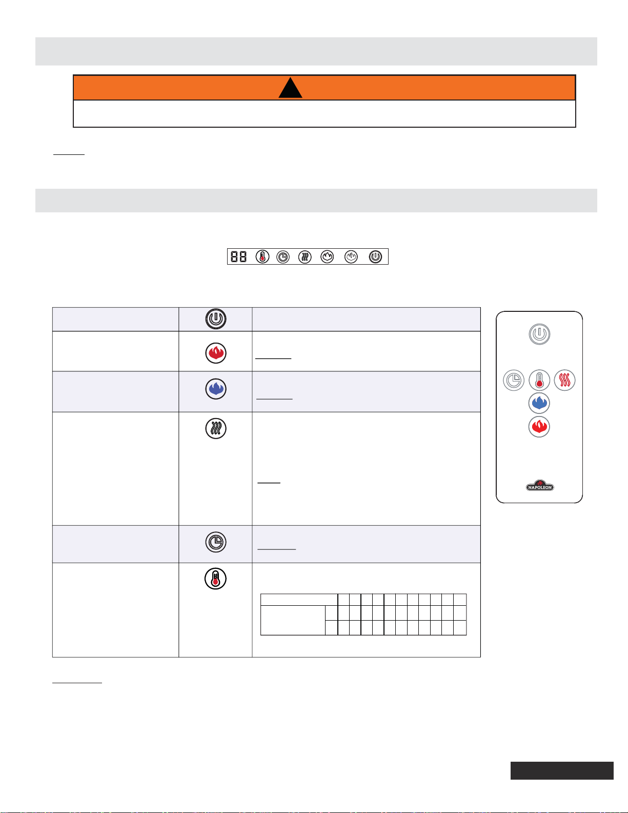
1.1 OPERATING TOUCH DISPLAY PANEL AND REMOTE CONTROL
The main power button is located on the front bottom right side of the appliance.
The touch display panel is shown by LED's on the front bottom right of the appliance. The LED's will
disappear after 10 seconds of no function change. The Main Power button will be dim.
POWER
FLAME - ORANGE
FLAME - BLUE
HEATER
TIMER
TEMPERATURE
Turns the appliance ON/OFF.
Controls Orange Flame brightness.
6 Settings: ( F5-F4-F3-F2-F1-F0 ) Flame dims from F5 to F1.
F5 is the brightest setting and F0 is off.
Controls Blue Flame brightness.
6 Settings: ( F5-F4-F3-F2-F1-F0 ) Flame dims from F5 to F1.
F5 is the brightest setting and F0 is off..
Controls the Heater.
Press button to initiate the heater.
(H0) no heater or blower.
(BL) blower only.
(H1), heater blows warm air (750W)
(H2), heater blows hot air (1500W)
NOTE: Heater functions cycle from H0-BL-H1-H2, Press
and hold the heater button for 5s, the heater and
temperature setting will be locked onto the selected
setting. Hold the button for 5s again, the heater will be
unlocked.
Controls the Timer.
9 Settings: (0.5h, 1h, 2h, 3h, 4h, 5h, 6h, 7h, 8h) Press button
until reach desired setting.
1. Press once: Touch panel indicator becomes active.
2. Press again until desired setting is reached. Digital display
shows setting circles as below.
Display Value
Temperature
NOTE: Press the button for 5 seconds, the temperature
setting will switch from °C to °F. Same way from °F to °C.
0123456789N
°
C
18 19
20 21 22 23 24 25 26 27
64 66
°
F
68 70 72 74 76 78 80 82
ON
ON
WARNING: Do not move or remove the front panel, when the appliance is plugged in and operating.
This will cause the remote control and touch panel to no longer function.
EN
3
W415-1698 / 12.20.16
Page 4
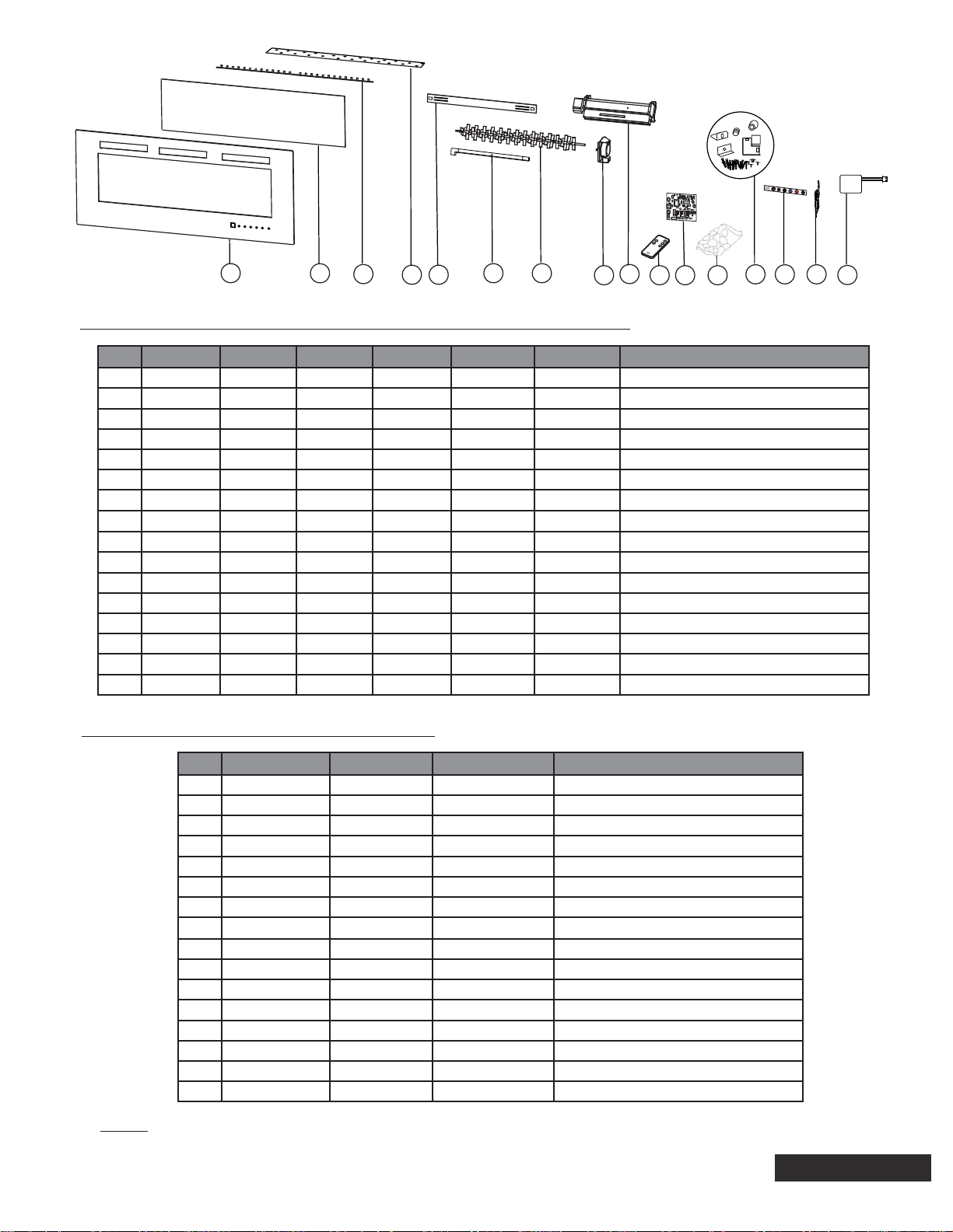
2.0 REPLACEMENT PARTS
!
WARNING
FAILURE TO POSITION THE PARTS IN ACCORDANCE WITH THIS MANUAL OR FAILURE TO USE
ONLY PARTS SPECIFICALLY APPROVED WITH THIS APPLIANCE MAY RESULT IN PROPERTY
DAMAGE OR PERSONAL INJURY.
Contact your dealer for questions concerning prices and policies on replacement parts. Normally, all parts
can be ordered through your Authorized dealer / distributor.
FOR WARRANTY REPLACEMENT PARTS, A PHOTOCOPY OF THE ORIGINAL INVOICE WILL BE
REQUIRED TO HONOUR THE CLAIM.
When ordering replacement parts always give the following information:
• Model & Serial Number of appliance
• Installation date of appliance
• Part number
• Description of part
• Finish
PARTS, PART NUMBERS AND AVAILABILITY ARE SUBJECT TO CHANGE WITHOUT NOTICE.
PARTS IDENTIFIED AS STOCKED WILL BE DELIVERED WITHIN 2 TO 5 BUSINESS DAYS FOR MOST
DELIVERY DESTINATIONS.
PARTS NOT IDENTIFIED AS STOCKED WILL BE DELIVERED WITHIN A 2 TO 4 WEEK PERIOD, FOR
MOST CASES.
PARTS IDENTIFIED AS ‘SO’ ARE SPECIAL ORDER AND CAN TAKE UP TO 90 DAYS FOR DELIVERY.
41.1C
For after sales service, please call 1-888-721-8324
EN
W415-1698 / 12.20.16
4
Page 5
1
2
3
4
5
6
7
9
8 10 12
11
13
14 15
NEFL32FH / NEFL42FH / NEFL50FH / NEFL60FH / NEFL72FH / NEFL100FH
REF. NEFL32FH NEFL42FH NEFL50FH NEFL60FH NEFL72FH NEFL100FH DESCRIPTION
1 W300-0226 W300-0224 W300-0227 W300-0228 W300-0229 W300-0230 FRONT GLASS
2 W475-1192 W475-1185 W475-1193 W475-1194 W475-1195 W475-1196 ACRYLIC PLASTIC PANEL
3 W405-0033 W405-0033 W405-0033 W405-0037 W405-0037 W405-0037 LED LIGHT
4 W497-0014 W497-0013 W497-0015 W497-0016 W497-0017 W497-0018 PLASTIC STRIP
5 W080-1616 W080-1616 W080-1616 W080-1616 W080-1616 W080-1621 WALL MOUNTING BRACKET
6 W200-0571 W200-0572 W200-0572 W200-0572 W200-0572 W200-0572 CORD COVER
7 W527-0009 W527-0008 W527-0010 W527-0011 W527-0012 W527-0013 REFLECTOR SPINDLE
8 W435-0077 W435-0077 W435-0077 W435-0077 W435-0077 W435-0077 SYNCHRONUS MOTOR
9 W010-3728 W010-3728 W010-3728 W010-3728 W010-3728 W010-3728 BLOWER AND HEATER ASSEMBLY
10 W190-0095 W190-0095 W190-0095 W190-0095 W190-0095 W190-0095 REMOTE CONTROL
11 W190-0096 W190-0096 W190-0096 W190-0101 W190-0101 W190-0101 CIRCUIT BOARD
12 W497-0019 W497-0020 W497-0021 W497-0022 W497-0023 W497-0024 CRYSTAL
13 W370-0050 W370-0050 W370-0050 W370-0055 W370-0055 W370-0057 HARDWARE KIT
14 W475-1184 W475-1184 W475-1184 W475-1184 W475-1184 W475-1184 CONTROL PANEL (WITH REMOTE RECEIVER)
15 W750-0370 W750-0371 W750-0372 W750-0373 W750-0374 W750-0375 WIRE HARNESS
16 W690-0021 W690-0021 W690-0021 W690-0021 W690-0021 W690-0021 THERMOSTAT
16
NEFL42FH-MT / NEFL50FH-MT / NEFL60FH-MT
REF. NEFL42FH-MT NEFL50FH-MT NEFL60FH-MT DESCRIPTION
1 W300-0224 W300-0227 W300-0228 FRONT GLASS
2 W475-1185 W475-1193 W475-1194 ACRYLIC PLASTIC PANEL
3 W405-0033 W405-0033 W405-0037 LED LIGHT
4 W497-0013 W497-0015 W497-0016 PLASTIC STRIP
5 W080-1616 W080-1616 W080-1616 WALL MOUNTING BRACKET
6 W200-0572 W200-0572 W200-0572 CORD COVER
7 W527-0008 W527-0010 W527-0011 REFLECTOR SPINDLE
8 W435-0077 W435-0077 W435-0077 SYNCHRONUS MOTOR
9 W010-3728
10 W190-0095 W190-0095 W190-0095 REMOTE CONTROL
11 W190-0096 W190-0096 W190-0101 CIRCUIT BOARD
12 W497-0020 W497-0021 W497-0022 CRYSTAL
13 W370-0050 W370-0050 W370-0055 HARDWARE KIT
14 W475-1184 W475-1184 W475-1184 CONTROL PANEL (WITH REMOTE RECEIVER)
15 W750-0371 W750-0372 W750-0373 WIRE HARNESS
16 W690-0021 W690-0021 W690-0021 THERMOSTAT
W010-3728 W010-3728 BLOWER AND HEATER ASSEMBLY
NOTE: Care must be taken when removing and disposing of any broken glass or damaged
components. Ensure to vacuum up any broken glass from inside the appliance before operation.
5
EN
W415-1698 / 12.20.16
Page 6
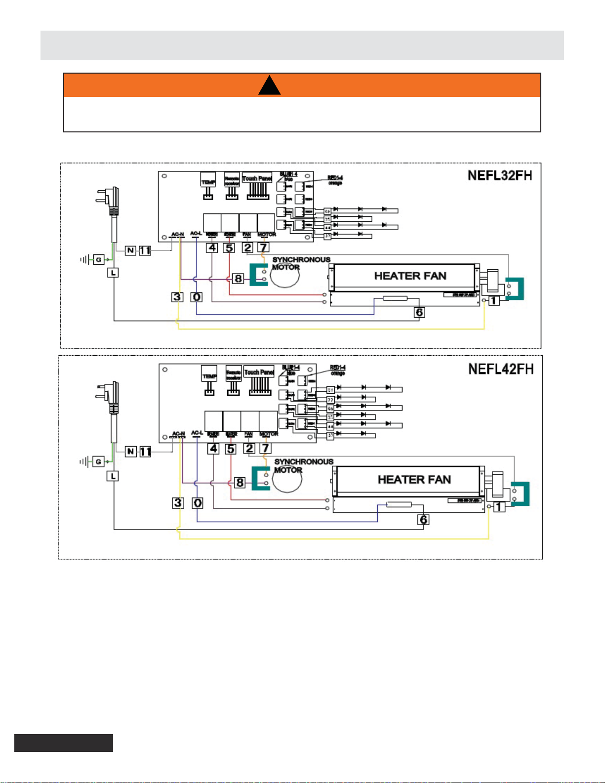
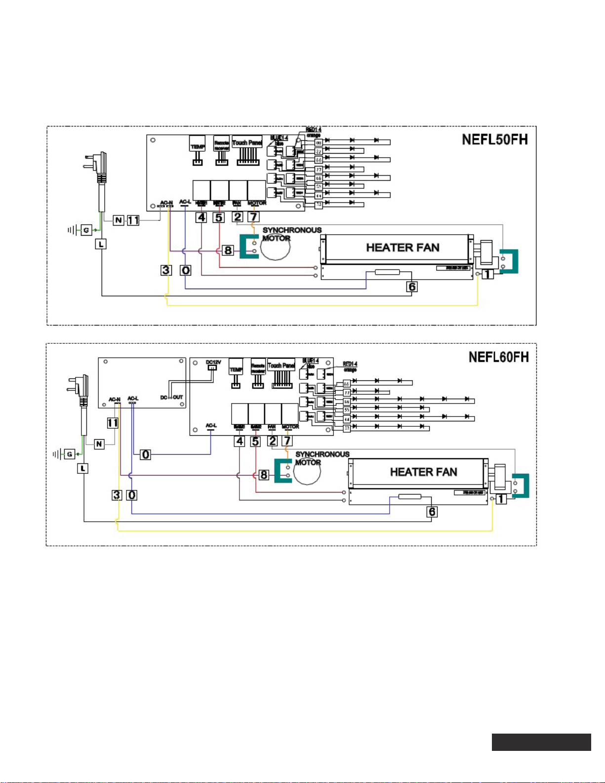
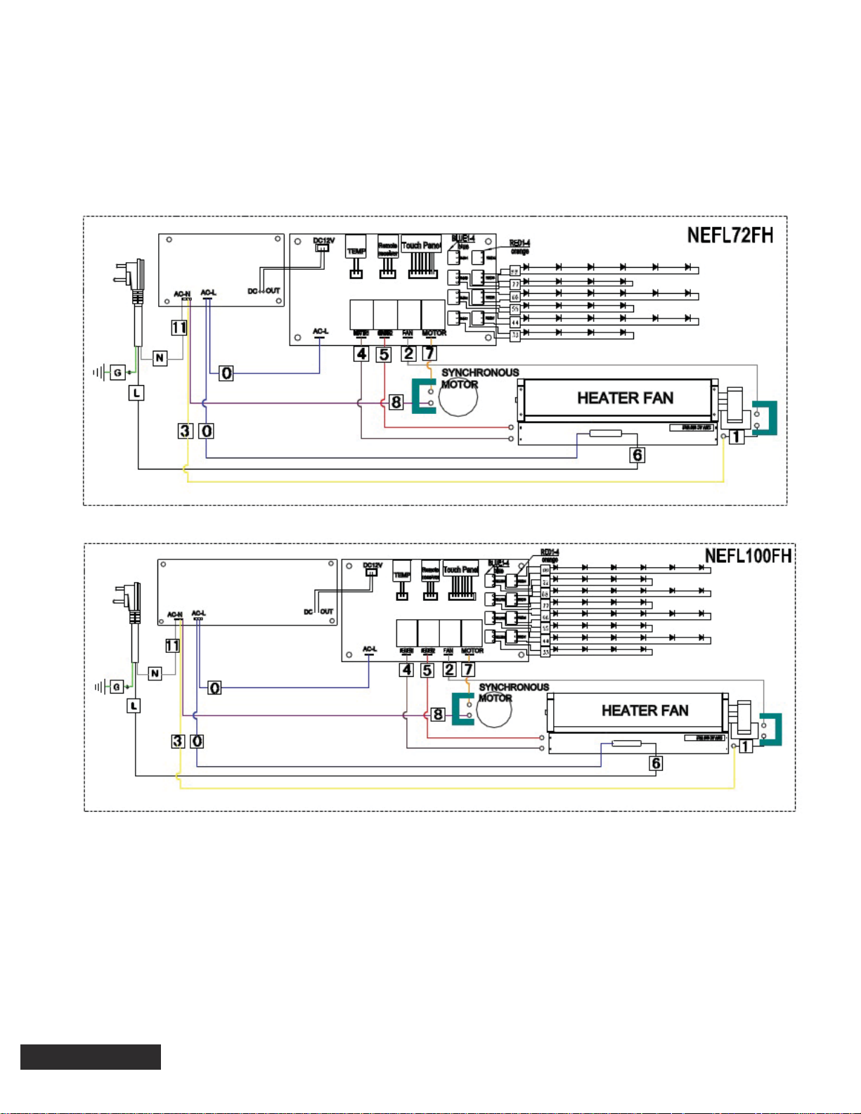
3.0 WIRING DIAGRAM
!
WARNING
TURN OFF THE APPLIANCE COMPLETELY AND LET COOL BEFORE SERVICING. ONLY A QUALIFIED
SERVICE PERSON SHOULD SERVICE AND REPAIR THIS ELECTRIC APPLIANCE.
EN
W415-1698 / 12.20.16
6
Page 7
EN
7
W415-1698 / 12.20.16
Page 8
EN
W415-1698 / 12.20.16
8
Page 9
4.0 TROUBLESHOOTING
!
WARNING
TURN OFF THE APPLIANCE COMPLETELY AND LET THE APPLIANCE COOL DOWN BEFORE SERVICING.
IF YOU ARE EXPERIENCING ANY OF THESE ISSUES, UNPLUG APPLIANCE FROM THE POWER OR TURN OFF
CIRCUIT BREAKER FOR 30 SECONDS TO FACTORY RESET THE APPLIANCE.
FOR ALL HARDWIRED APPLIANCES, DO A VOLTAGE TEST TO ENSURE THAT THERE IS NO POWER RUNNING
THROUGH THE UNIT.
TO ACCESS COMPONENTS OF THE APPLIANCE, REFER TO SECTION 5.0 SERVICE PREPARATION
SYMPTOM PROBLEM TEST SOLUTION
Dim or no fl ame Dim Flame
No moving fl ame (LED light on)
No LED light
Missing a fl ame colour 1. Press corresponding button to turn on colour
1. Press the fl ame buttons on the control panel to cycle through
brightness levels in order check if the light will get brighter.
2. If light is still dim, refer to section 4.1
1. Press the fl ame buttons on the control panel to cycle through
the fl ame settings (from F1, F2, F3, to F0) as this could restart the
refl ector spindle to animate the fl ame.
2. If fl ame is still not moving, refer to section 4.1
1. Press the fl ame buttons on the control panel to cycle through
the brightness levels
2. If the LED light is still off, refer to section 4.1
2. If the desired colour is still not functioning, refer to section 4.1
No warm air is coming
out of the appliance
Appliance fl ashes on
and off
Heater shuts off and
LED fl ashes after 30
seconds
Heater is on but little
to no heat is produced
E1 Error Code
E2 Error Code
Appliance is tripping
circuit breaker
Room temperature is higher than
the set temperature setting
Appliance has overheated
Blower malfunction
One or more heating elements
has malfunctioned
Thermostat failure
Thermostat or PCB is shorting
Current is overloading the
circuit or a short created by an
internal component
1. Set temperature to a higher setting with remote control.
2. If heater does not turn on, proceed with "LED indicator light is
fl ashing" test solution.
1. Unplug the appliance and wait 15-20 minutes for the appliance
to cool down
2. Ensure nothing is blocking the air fl ow from the exhaust of the
appliance
3. Plug in the appliance. If problem persists, refer to section 4.2
1. Refer to section 4.2
1. Ensure wire connections are fi rmly connected at the thermostat
and PCB.
2. If appliance is still showing error code E1, replace thermostat.
Refer to section 6.5
1. Ensure wire connections are fi rmly connected at the thermostat and
PCB.
2. If unit is still showing error code E2, replace thermostat.
Refer to section 6.5
3. If unit is still showing error code E2, replace the PCB.
Refer to section 6.2
1. Inspect connected electrical load (appliance must be connected to
15A, grounded, and a dedicated circuit).
2. Inspect all internal components. Refer to section 4.1 - 4.3
Appliance beeps when
plugged in but will not
turn on
Control panel issue
1. Remove front glass and ensure yellow protective cover is removed
from the control panel buttons
2. If unit still does not work, inspect control panel. If it needs to be
replaced, refer to section 6.3
EN
9
W415-1698 / 12.20.16
Page 10

4.1 FLAME LED TESTING
START HERE
Perform LED testing
(Section 4.1.1)
YES
Is the refl ector spindle
turning?
NO
Perform motor and LED testing
(Section 4.1.1 - 4.1.2)
4.1.1 LED TESTING
Unplug the appliance
(if hardwired, turn off circuit breaker)
Ensure the wires from the fl ame LED
are not pinched, frayed, and are fi rmly
connected on the PCB and fl ame LED
(Figure 1)
Ensure refl ector spindle is free
of any obstructions
Plug in the appliance and press
power button on the control panel
(if hardwired, turn on circuit breaker)
Cycle through the brightness
settings by pushing the fl ame
button on the control panel
NO
Are the LEDs on?
START HERE
Unplug the appliance
(If hardwired, turn off circuit breaker)
Appliance is functioning accordingly.
YES
Is the refl ector spindle
turning?
NO
Perform motor testing
(Section 4.1.2)
YES
Set multimeter to read
DC voltage
Plug the appliance
(If hardwired, turn on circuit breaker)
Ensure to set the brightest
LED setting
Unclip the wire harness from the
corresponding terminal for the LED
strip that you are testing (Figure 2)
Place positive probe on the corresponding
LED on the PCB (Figure 3)
Place negative probe on the corresponding
LED on the PCB (Figure 3)
Is the voltage reading
12V DC?
NO
Replace the wire harness
Refer to section 6.7 (Wire
Harness Replacement)
YES
Replace the fl ame LED strip.
Refer to section 6.4
(LED Replacement)
EN
W415-1698 / 12.20.16
10
Page 11

FIGURES
-
+
Fig. 1
Fig. 2
Fig. 3
FLAME LED TERMINALS
11
EN
W415-1698 / 12.20.16
Page 12

4.1.2 MOTOR TESTING
START HERE
Replace the PCB
Refer to section 6.2 (Control
Board Replacement)
Unplug the appliance
(If hardwired, turn off circuit breaker)
Set multimeter to read
AC voltage
Disconnect the wire on the
MOTOR terminal on the PCB
Plug in the appliance and press power
button on the control panel
(If hardwired, turn on circuit breaker)
Place positive probe on the MOTOR
terminal of the PCB (Figure 4)
Place negative probe on the AC-N / AC-N1
terminal of the PCB (Figure 5)
Is there a voltage reading
NO
approximately 120V AC?
YES
Unplug the appliance
(If hardwired, turn off circuit breaker)
Replace the wire harness
Refer to section 6.7 (Wire
Harness Replacement)
Reconnect the wire into the
MOTOR terminal on the PCB
Follow the wire from the motor until
you reach the plastic connectors and
disconnect them (Figure 6)
Using the female wire connector coming from
the PCB, place positive probe into the terminal
with the orange wire and the negative probe
into the terminal with the purple wire (Figure 7)
Plug in the appliance and press
power button on the control panel
(If hardwired, turn on circuit breaker)
NO
Is the voltage reading
approximately 120V AC?
YES
Replace the motor
Refer to section 6.1
(Motor Replacement)
EN
W415-1698 / 12.20.16
12
Page 13

FIGURES
MOTOR
TERMINAL
+
Fig. 4
Fig. 5
-
AC-N1
Fig. 6
Fig. 7
+
-
13
EN
W415-1698 / 12.20.16
Page 14

4.2 HEATER/BLOWER TESTING
START HERE
Perform heater testing
(Section 4.3.2)
YES
Is the blower on?
NO
Perform blower and heater testing
(Section 4.3.1 - 4.3.2)
4.2.1 BLOWER TESTING
START HERE
Unplug the appliance
(if hardwired, turn off circuit breaker)
Perform a visual check for burns,
sparks, damages, etc. Replace any
damaged parts
Ensure the wires from FAN, HEATER1,
and HEATER 2 terminals are not
pinched, frayed, and are fi rmly
connected on both sides (Figure 8)
Plug in the appliance
(if hardwired, turn on circuit breaker)
Turn on heater by pressing the heater
button on the control panel
YES
Is the heater on?
NO
Appliance is functioning
accordingly.
YES
Is the blower on?
NO
Perform blower testing
(Section 4.3.1)
Unplug the appliance
(if hardwired, turn off circuit breaker)
Does the fan spin with little
or no resistance?
Set multimeter to
read AC voltage
Disconnect the grey wire connector
on the FAN terminal on the PCB
(Figure 9)
Plug the appliance
(if hardwired, turn on circuit breaker)
Place the positive probe on the
FAN terminal of the PCB
(Figure 10)
Place the negative probe on the
AC-N / AC-N1 terminal of the PCB
(Figure 11)
Turn on heater by pressing the heater
button on the control panel
Is the voltage reading
approximately 120V AC?
YES
Unplug the appliance
(if hardwired, turn off circuit breaker)
Follow the wire from the fan
until you reach the plastic
connectors and disconnect it
Identify which side of the
disconnected wire is coming from
the PCB (female connector)
Replace the wire harness
Refer to section 6.7 (Wire
Harness Replacement)
NO
Replace the PCB
Refer to section 6.2 (Control
Board Replacement)
Plug in the appliance and press
power button on the control panel
(if hardwired, turn on circuit breaker)
Place the positive probe into the terminal
with the grey wire (Figure 12)
Place the negative probe into the
terminal with the white wire (Figure 12)
Turn on heater by pressing the heater
button on the control panel
Is the voltage reading
NO
approximately 120V AC?
EN
W415-1698 / 12.20.16
YES
Defective blower
Refer to section 6.6 (Heater, Blower,
and High Limit Switch Replacement)
14
Page 15

FIGURES
FAN
TERMINAL
Fig. 8
Fig. 9
+
Fig. 10 Fig. 11
-
AC-N1
Fig. 12
+
-
15
EN
W415-1698 / 12.20.16
Page 16

4.2.2 HEATER TESTING
START HERE
Turn appliance on
Set heater setting on H2
Set a clamp multimeter to read
amperage and clamp around L1,
wire #0 (Figure 13)
Is the amperage reading
less than 1A?
YES
Set multimeter to
read AC voltage
Check power supply for
120V AC (Figure 18)
NO
!
WARNING
RISK OF ELECTRICAL SHOCK.
Is the amperage reading
approximately 5-6A?
YES
Cycle through the heat settings
Set heater setting on H2
Using a clamp multimeter,
clamp around wire #4 then
wire #5 (Figure 19 & 20)
Did both wires read
approximately 5-6A?
YES
Appliance is functioning
accordingly
NO
Appliance is functioning accordingly
YES
Is the amperage reading
NO
approximately 10-12A?
NO
Unplug the appliance
(if hardwired, turn off circuit breaker)
Ensure wire connections are fi rmly
connected at the heater/blower
assembly and at the PCB.
Refer to the wiring diagram
Set multimeter to
read AC voltage
Place negative probe on
the AC-N / AC-N1 terminal
of the PCB (Figure 14)
Place positive probe on the AC-L
terminal of the PCB (Figure 15)
Is the voltage reading
approximately 120V AC?
Are the connections to
the junction box, heater,
and thermal cutoff fi rmly
secured?
Reconnect any loose
wires
Replace PCB
Refer to section 6.2
(Control Board
Replacement)
(if hardwired, turn off circuit breaker)
Replace wire harness
Refer to section 6.7 (Wire
Harness Replacement)
EN
W415-1698 / 12.20.16
Contact a certifi ed
NO
YES
YES
NO
NO
Did both terminals
read approximately
120V AC?
Unplug the appliance
Check continuity of the heater
wire #4 and #5 to neutral
(Figures 21, 22, and 23)
Is there continuity?
NO
electrician to inspect
YES
16
house wiring
YES
NO
Check power
supply for 120V AC
(Figure 18)
Plug in the appliance and press
power button on the control panel (if
hardwired, turn on circuit breaker)
Place positive probe on the HEATER1
and then HEATER2 terminals of the PCB
Measure the ohm value of HEATER1 and
HEATER2 by placing the probes on each
side of HEATER1 and HEATER2 terminals
on the heating element (Figures 24 & 25)
*Keep the negative probe on AC-N / AC-N1
Is the nominal voltage
reading approximately
120V AC?
YES
Unplug the appliance
(if hardwired, turn off
circuit breaker)
Unplug the wires from
HEATER1 and HEATER2
terminals on the PCB
Set heater setting on H2
(Figures 16 &17)
Did both heating
elements read 19-20 Ω?
NO
Defective heater
Refer to section 6.6
(Heater, Blower, and
High Limit Switch
Replacement)
Page 17

FIGURES
Fig. 13
-
Fig. 14
+
Fig. 15
+
-
Fig. 19
Fig. 21
+
Fig. 18
+
Fig. 20
Fig. 22
+
+
Fig. 16
Fig. 17
+
+
-
Fig. 23
-
Fig. 24
Fig. 25
-
17
EN
W415-1698 / 12.20.16
Page 18

4.3 HIGH LIMIT SWITCH TESTING
START HERE
Unplug the appliance
(if hardwired, turn off circuit breaker)
Leave appliance turned off for 15-20 minutes
for the appliance to cool down
Inspect wires to and from the high limit
switch to ensure there are no damaged
or disconnected wires
If the appliance is shutting off constantly 8-10 sec
after heater button is pushed, the high limit
switch and/or circuit is open
Inspect wires # 2, 4, 5, 6, and 11.
Refer to the wiring diagram
Ensure there are no frayed
or damaged wires
Are there any broken
connectors or wires?
YES
Replace wire harness
Refer to section 6.7 (Wire
Harness Replacement)
NO
NOTE: THIS ENSURES THE HIGH
LIMIT SWITCH HAS COOLED
DOWN AND RESET
Set the multimeter to read AC voltage
Place negative probe on AC-N / AC-N1
terminal of the PCB (Figure 26)
Place the positive probe on the left terminal
of the high limit switch (Figure 27)
Is the voltage reading
approximately 120V AC?
YES
Keep the negative probe on AC-N / AC-
N1 terminal of the PCB and place the
positive probe on the right terminal of the
high limit switch (Figure 28)
Is the voltage reading
approximately 120V AC?
YES
NO
NO
Check power supply
for 120V
Defective high limit
switch. Refer to
section 5.12
(High Limit Switch,
Heater, and Blower
Replacement)
EN
W415-1698 / 12.20.16
Replace wire harness
Refer to section 6.7 (Wire
Harness Replacement)
18
Page 19

FIGURES
-
Fig. 26
Fig. 27
+
+
Fig. 28
19
EN
W415-1698 / 12.20.16
Page 20

5.0 SERVICE PREPARATION
!
WARNING
ALWAYS DISCONNECT THE POWER AND ALLOW THE ELECTRIC APPLIANCE TO COOL BEFORE
PERFORMING ANY CLEANING, MAINTENANCE, OR RELOCATION OF THIS ELECTRIC APPLIANCE.
TURN CONTROLS TO OFF AND REMOVE PLUG FROM OUTLET OR TURN OFF THE HOUSE
CIRCUIT BREAKER TO ELECTRIC APPLIANCE RECEPTACLE.
FRONT REMOVAL
1. Unscrew the top 2 screws that are securing the front bracket.
2. Lift the front glass up to unhook the front brackets from the hooking tabs and pull the front glass
away from the appliance.
1
EN
W415-1698 / 12.20.16
2
20
Page 21

MEDIA TRAY REMOVAL
1. Remove the acrylic crystals from the media tray.
2. Unscrew the media tray. Depending on the model, screws vary in numbers.
3. Remove the media tray from the appliance.
PLASTIC PANEL REMOVAL
1. Unscrew and remove the top plastic panel bracket.
2. unscrew the side plastic panel brackets. Depending on the model, screws will vary in numbers.
3. Pull the plastic panel using the sides on the upper half of the panel.
4. Carefully lift the plastic panel out of the appliance.
1
2
3
21
EN
W415-1698 / 12.20.16
Page 22

CONTROL BOARD COVER REMOVAL
1. Remove the 4 screws on the control board cover plate.
METAL FLAME CUTOUT REMOVAL
1. Remove the screws on the side and bottom tray of the metal cutout. Depeneding on the model, the
number of screws will vary.
EN
W415-1698 / 12.20.16
22
Page 23

CONTROL PANEL PLATE REMOVAL
1. Remove the screws on the control panel plate. Depending on the model, the number of screws will vary.
BLOWER / HEATER TRIM REMOVAL
1. Unscrew and remove middle blower/heater trim.
2. Unscrew and remove the side blower/heater trims to access the heater, blower, and high limit switch
assembly.
1
2
23
EN
W415-1698 / 12.20.16
Page 24

6.0 REPLACING COMPONENTS
!
WARNING
PREPARATION FOR MAINTENANCE
ALWAYS DISCONNECT THE POWER AND ALLOW THE ELECTRIC APPLIANCE TO COOL BEFORE
PERFORMING ANY CLEANING, MAINTENANCE, OR RELOCATION OF THIS ELECTRIC APPLIANCE.
TURN CONTROLS TO OFF AND REMOVE PLUG FROM OUTLET OR TURN OFF THE HOUSE
CIRCUIT BREAKER TO ELECTRIC APPLIANCE RECEPTACLE.
TO ACCESS THE FOLLOWING COMPONENTS, REFER TO THE SERVICE PREPARATION SECTION.
6.1 MOTOR AND REFLECTOR SPINDLE REPLACEMENT
1. Remove 2 screws that hold the motor and disconnect the wire connector.
2. Unplug the quick connect motor wire from the wire harness.
3. Pull the motor out of the unit. For ease of removal, turn the motor
slightly to remove it.
4. To remove the refl ector spindle, pull the refl ector away from the motor for it
to release.
5. Remove the rubber adapter from the motor.
6. Remove two screws holding the motor and take the motor out of the appliance.
7. Install new motor with the refl ector spindle and the rubber adapter.
8. Screw the new motor back into the motor bracket.
REFLECTOR SPINDLE
6.2 CONTROL BOARD REPLACEMENT
1. Unplug all the wires connected to the control board. For ease of wire disconnection, use a pair of
needle-nose pliers.
2. Remove control board from appliance. NOTE: To prevent stripping of the plastic plugs on the back
of the control board, hold the plugs with a pair of needle-noise pliers while removing each of the
screws.
3. Install the new control board into the appliance.
4. Connect all of the wires to the board.
MOTOR
EN
W415-1698 / 12.20.16
24
Page 25

6.3 CONTROL PANEL REPLACEMENT
1. Disconnect the quick connector from the control panel (Figure 1).
2. Push in the holding tabs of the control panel and gently push the control panel out of the plate (Figure 2).
3. Install the new control panel into the plate. Ensure to push the new control panel gently until you hear a
click to confi rm that the holding tabs are secure.
4. Plug the quick connector to the new control panel.
FIG. 1 FIG. 2
6.4 LED REPLACEMENT
1. Find the connector on the PCB for the LED strip you want to replace and follow it to the LED strip.
2. Cut the cable tie and release the wire harness from the LED.
3. Use a pair of needle-nose pliers to pinch the plastic connectors to release the LED.
4. Install the new LED strip and plug in the necessary wire connectors to the new LED strip.
25
EN
W415-1698 / 12.20.16
Page 26

6.5 REMOTE RECEIVER / THERMOSTAT REPLACEMENT
1. Find the connector of the component you need to replace and unplug it on the PCB.
2. Cut the cable ties.
3. Unscrew the component from the appliance.
4. Screw the new compnent and connect the wires to the appropriate connectors.
5. Using a cable tie, secure the wires.
RECEIVER
THERMOSTAT
EN
W415-1698 / 12.20.16
26
Page 27

6.6 HEATER, BLOWER, AND HIGH LIMIT SWITCH ASSEMBLY REPLACEMENT
1. Remove the screws from the holding brackets on each side of the blower.
2. Remove heater, blower, and high limit switch assembly from the appliance.
3. Unplug the wire connectors connected to the assembly.
4. Install the new heater, blower, and high limit switch assembly and secure by fastening the assembly to
the holding brackets.
HOLDING BRACKETS
HEATER, BLOWER, AND HIGH LIMIT SWITCH ASSEMBLY
27
EN
W415-1698 / 12.20.16
Page 28

6.7 WIRE HARNESS REPLACEMENT
1. Remove wire connections from the PCB and heater/blower/high limit switch assembly.
2. Replace wire harness assembly. Refer to wiring diagram.
PCB WITH WIRE CONNECTORS PCB WITHOUT WIRE CONNECTORS
6.8 REMOTE BATTERY INSTALLATION
NOTE: The remote control has a removable plastic tab to prolong the battery life while shipping,
remove the tab for the remote control to function.
1. To replace the existing battery remove the
battery holder.
2. To remove the battery holder turn remote onto
rear side and press the left side leaver towards
the center while pulling the battery holder out
using the slot provided.
3. Replace existing battery, type CR 2025, with a
new battery and reinstall the battery holder into
the remote by sliding it into position, as shown.
BATTERY (CR 2025)
BATTERY HOLDER
NOTE: The remote control must remain within 5 meters or 17 feet of the appliance to be effective, this
range may be reduced when battery power is depleted.
REMOTE
(REAR SIDE)
EN
W415-1698 / 12.20.16
28
Page 29

7.0 NOTES
44.1
29
EN
W415-1698 / 12.20.16
Page 30

Products
®
Other Napoleon
'JSFQMBDF*OTFSUTt$IBSDPBM(SJMMT t(BT'JSFQMBDFTt8BUFSGBMMTt8PPE4UPWFT
)FBUJOH$PPMJOHt&MFDUSJD'JSFQMBDFTt0VUEPPS'JSFQMBDFTt(BT(SJMMT
/BQPMFPO3PBE#BSSJF0OUBSJP$BOBEB-.(
#BZWJFX%SJWF#BSSJF0OUBSJP$BOBEB-/:
.JMMFS%SJWF$SJUUFOEFO,FOUVDLZ64"
5SBOT$BOBEB)JHIXBZ.POUSFBM2VFCFD$BOBEB)5"
'JSFQMBDFT)FBUJOH$PPMJOHDBMMt(SJMMTDBMM
napoleonproducts.com
 Loading...