

Page 1
INSTALLER: LEAVE THIS MANUAL WITH THE APPLIANCE.
CONSUMER: RETAIN THIS MANUAL FOR FUTURE REFERENCE.
NEVER LEAVE CHILDREN OR OTHER AT RISK INDIVIDUALS ALONE WITH THE APPLIANCE.
INSTALLATION AND
EN
OPERATING INSTRUCTIONS
CERTIFIED UNDER CANADIAN AND AMERICAN NATIONAL STANDARDS: CSA C22.2 No.46 / UL 1278 CSA STANDARD
NEFB30GL
ELECTRIC FIREPLACE
FR
PG
27
SAFETY INFORMATION
!
WARNING
If the information in these instructions
are not followed exactly, a fi re may result
causing property damage, personal injury
or loss of life.
- Do not store or use gasoline or other fl ammable
vapors and liquids in the vicinity of this or any
other appliance.
Wolf Steel Ltd., 24 Napoleon Rd., Barrie, ON, L4M 0G8 Canada /
103 Miller Drive, Crittenden, Kentucky, USA, 41030
Phone (705)721-1212 Fax (705)720-9081 www.napoleonfi replaces.com hearth@napoleonproducts.com
$10.00
1.16F
W415-2166 / A / 06.29.16
Page 2

EN
2
TABLE OF CONTENTS
1.0 INTRODUCTION 3
1.1 DIMENSIONS 4
1.2 LISTING APPROVALS 4
1.3 GENERAL INSTRUCTIONS 5
1.4 LABEL LOCATION 6
2.0 LOCATING APPLIANCE 7
2.1 UNPACKING AND TESTING APPLIANCE 7
2.2 GROUNDING APPLIANCE 8
3.0 INSTALLATION 9
3.1 MINIMUM CLEARANCE TO COMBUSTIBLES 10
3.2 MINIMUM MANTEL CLEARANCES 10
3.3 NEW CONSTRUCTION OR RENOVATION 11
3.4 INSTALLING THE APPLIANCE 11
3.5 THERMOSTAT AND THERMAL SENSOR INSTALLATION 11
3.6 HARD-WIRE INSTALLATION 12
3.7 WIRING DIAGRAM 13
4.0 FRAMING 14
5.0 FINISHING 15
5.1 HEARTH 15
5.2 COLD CLIMATE INSTALLATION 15
5.3 FINISHING CHECKLIST 15
6.0 OPERATING INSTRUCTIONS 16
6.1 OPERATING BY REMOTE CONTROL 17
6.2 CRYSTAL EMBER PLACEMENT 18
6.3 LED / REMOTE RECEIVER / THERMOSTAT REPLACEMENT 19
6.4 FUSE REPLACEMENT 19
7.0 REPLACEMENT PARTS 20
7.1 REPLACEMENT PARTS DIAGRAM 21
8.0 TROUBLESHOOTING 22
9.0 WARRANTY 23
10.0 SERVICE HISTORY 24
11.0 NOTES 25
NOTE: Changes, other than editorial, are denoted by a vertical line in the margin.
W415- 2166 / A / 06.29.16
Page 3
1.0 INTRODUCTION
!
WARNING
3
• THIS APPLIANCE IS HOT WHEN OPERATED AND CAN CAUSE SEVERE BURNS IF
CONTACTED.
• Do not operate appliance before reading and understanding operating instructions. Failure to operate
appliance according to operating instructions could cause fi re or injury.
• Risk of burns. Power to the appliance should be turned off and the appliance allowed to cool before
servicing. To disconnect power to the appliance, turn controls to off, then remove plug from outlet.
• Do not install damaged, incomplete or substitute components.
• Do not burn wood or other materials in this appliance.
• Young children should be carefully supervised when they are in the same room as the appliance.
Toddlers, young children and others may be susceptible to accidental contact burns. A physical barrier
is recommended if there are at risk individuals in the house. To restrict access to an appliance or stove,
install an adjustable safety gate to keep toddlers, young children and other at risk individuals out of the
room and away from hot surfaces.
• Clothing or other fl ammable material should not be placed on or near the appliance.
• Due to high temperatures, the appliance should be located out of traffi c and away from furniture and
draperies.
• Ensure you have incorporated adequate safety measure to protect infants/toddlers from touching hot
surfaces.
• Even after the appliance is out, the glass and/or screen will remain hot for an extended period of time.
• Check with your local hearth specialty dealer for safety screens and hearth guards to protect children
from hot surfaces. These screens and guards must be fastened to the fl oor.
• Any safety screen or guard removed for servicing must be replaced prior to operating the appliance.
• It is imperative that the control compartments, circulating blower and its passageway in the appliance
and are kept clean. The appliance should be inspected before use and at least annually by a qualifi ed
service person. More frequent cleaning may be required due to excessive lint from carpeting, bedding
material, etc. The appliance area must be kept clear and free from combustible materials, gasoline and
other fl ammable vapors and liquids.
• Under no circumstances should this appliance be modifi ed.
• Do not use this appliance if any part has been under water. Immediately call a qualifi ed service technician
to inspect the appliance and to replace any part of the control system which has been under water.
• Do not operate the appliance with the glass door removed, cracked or broken. Replacement of the
glass should be done by a licensed or qualifi ed service person.
• Do not strike or slam shut the appliance glass door.
• Keep the packaging material out of reach of children and dispose of the material in a safe manner. As
with all plastic bags, these are not toys and should be kept away from children and infants.
• Servicing should be done only while the appliance is disconnected from the power supply circuit.
• Always unplug appliance when not in use.
• Do not operate this appliance with a damaged cord or plug after the appliance malfunctions, has been
dropped or damaged in any manner. Return appliance to authorized service facility for examination,
electrical or mechanical adjustment, or repair.
• Do not use outdoors.
• Never locate appliance where it may fall into a bathtub or other water container.
• Do not run cord under carpeting. Do not cover cord with throw rugs, runners, or the like. Arrange cord
away from traffi c area and where it will not be tripped over.
• Connect to properly grounded outlets only.
• Do not insert or allow foreign objects to enter any ventilation or exhaust opening as this may cause an
electric shock or fi re, or damage the appliance.
• To prevent a possible fi re, do not block air intakes or exhaust in any manner. Do not use on soft
surfaces, like a carpet, where openings may become blocked.
• Always plug appliances directly into a wall outlet/receptacle. Never use an extension cord or
relocatable power tap (outlet/power strip).
• Ensure clearances to combustibles are maintained when building a mantel or shelves above the
appliance. Elevated temperatures on the wall or in the air above the appliance can cause melting,
discolouration or damage to decorations, a T.V. or other electronic components.
3.7C
EN
W415-2166 / A / 06.29.16
Page 4
4
WARNING
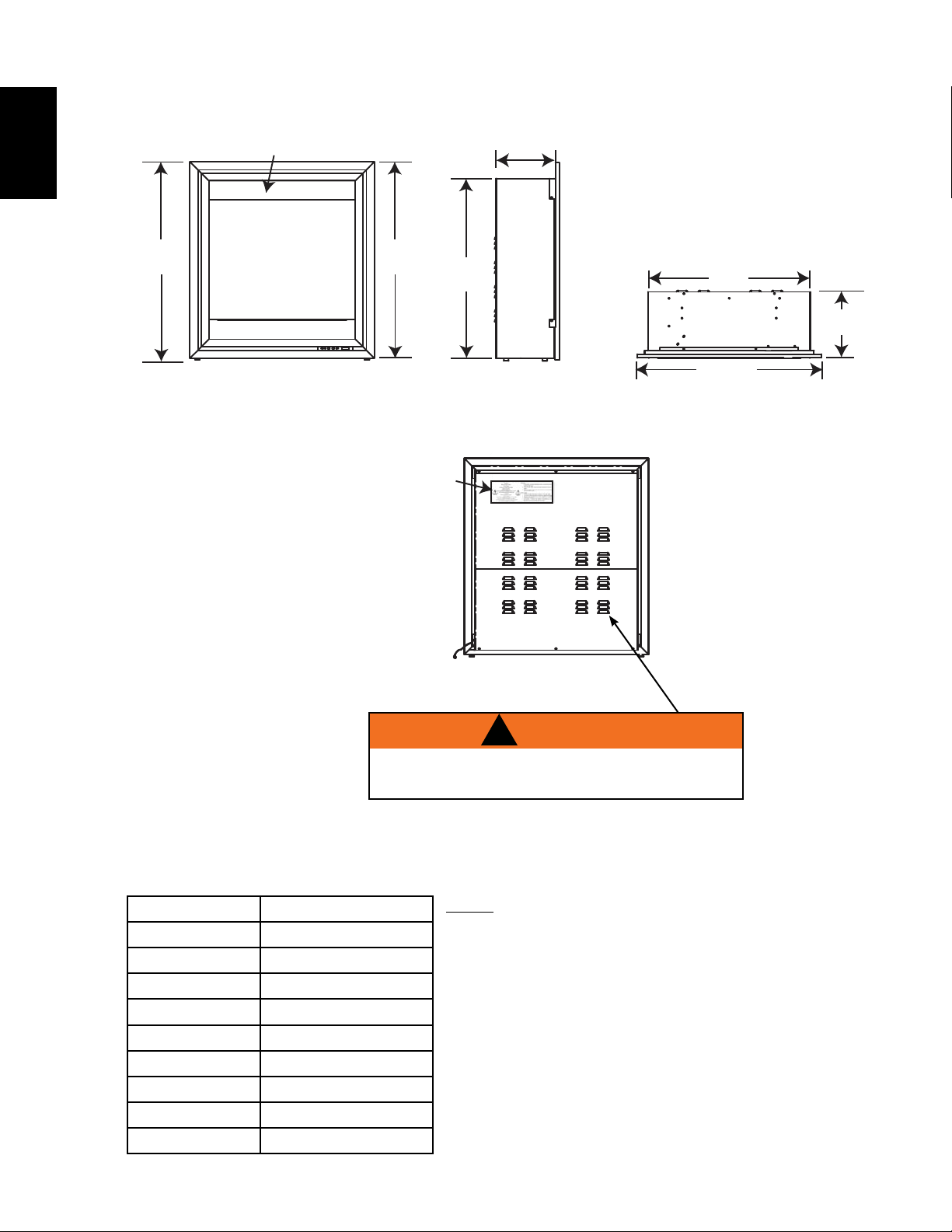
1.1 DIMENSIONS
EN
Heater vents - DO NOT COVER
1
32
/4”
32”
Rating
Plate &
Serial
Number
291/2”
10
”
261/2”
3
10
/4”
30”
1.2 LISTING APPROVALS
This appliance has been tested in accordance with the CSA Standards for fixed and location-dedicated
electric room appliances in the United States and Canada. If you need assistance during installation, please
contact your local dealer.
Model Number NEFB30GL
Description Electric Appliance
Voltage 120V AC
Watts MAX 1500W
Lamp LED
Appliance Width 30" (762mm)
Appliance Height 32 1/4" (820mm)
Appliance Depth 10 3/4" (273mm)
Net Weight 79 lbs (36kg)
Gross Weight 89 lbs (41kg)
Power Cord and Thermostat
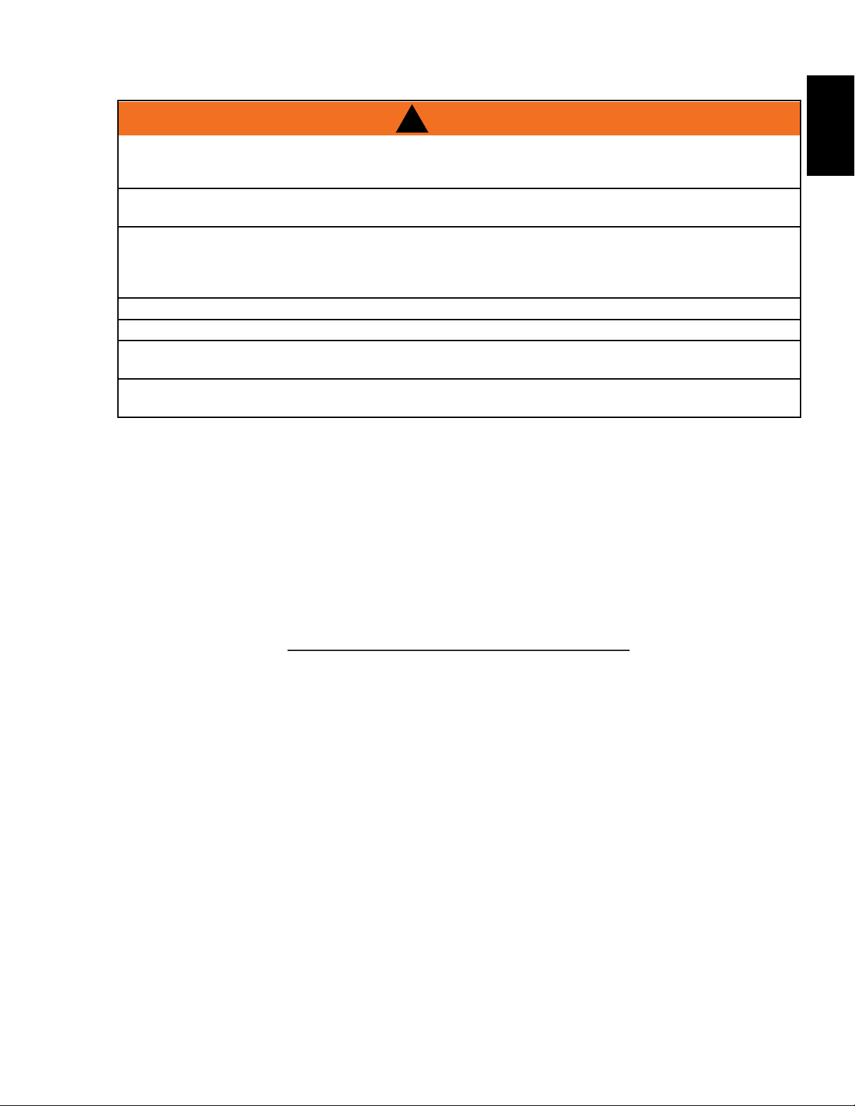
!
HEATER VENTS AND AIR OPENINGS CAN NOT
BE COVERED IN ANY CIRCUMSTANCES.
NOTE: This appliance must be electrically wired and
grounded in accordance with local codes or, in the absence
of local codes, with National Electric Code ANSI/NFPA
70-latest edition or the Canadian Electric Code, CSA C22.1
as appropriate.
W415- 2166 / A / 06.29.16
Page 5
1.3 GENERAL INSTRUCTIONS
A.
B.
C.
D.
E.
This electric appliance meets the construction and safety standards of H.U.D. for application in manufactured
homes when installed according to these instructions.
!
WARNING
READ THESE INSTRUCTIONS COMPLETELY BEFORE BEGINNING INSTALLATION. FAILURE TO
FOLLOW THEM COULD CAUSE AN APPLIANCE MALFUNCTION RESULTING IN SERIOUS INJURY
ALL ELECTRIC APPLIANCES HAVE HOT AND ARCING OR SPARKING PARTS INSIDE. DO NOT USE
IT IN AREAS WHERE GASOLINE, PAINT OR FLAMMABLE LIQUIDS ARE PRESENT.
THIS ELECTRIC APPLIANCE IS TESTED AND LISTED FOR USE ONLY WITH THE OPTIONAL
ACCESSORIES LISTED IN THESE INSTRUCTIONS. USE OF OPTIONAL ACCESSORIES NOT
SPECIFICALLY TESTED FOR THIS ELECTRIC APPLIANCE COULD VOID THE WARRANTY AND/OR
DO NOT OPEN. RISK OF ELECTRIC SHOCK. NO USER-SERVICEABLE PARTS INSIDE.
DO NOT USE DAMAGED ELECTRICAL CORDS.
SERVICING SHOULD BE DONE ONLY WHILE THE APPLIANCE IS DISCONNECTED FROM THE
TO PREVENT ELECTRIC SHOCK MATCH THE WIDE BLADE OF PLUG TO WIDE SLOT OF
Prior to plugging your appliance into an electrical outlet, verify that the house circuit breakers for the
outlet are on.
The appliance may emit a slight, harmless odour when fi rst used. This odour is normal and it is caused
by the initial heating of internal appliance elements and will not occur again.
If your appliance does not emit heat, consult the operation section of this manual for further
information.
Use with a CSA- or UL-certifi ed surge protector.
Do not route the power cord directly underneath the appliance.
5
EN
AND/OR PROPERTY DAMAGE.
RESULT IN A SAFETY HAZARD.
POWER SUPPLY CIRCUIT.
RECEPTACLE AND FULLY INSERT.
4.8B
W415-2166 / A / 06.29.16
Page 6
EN
6
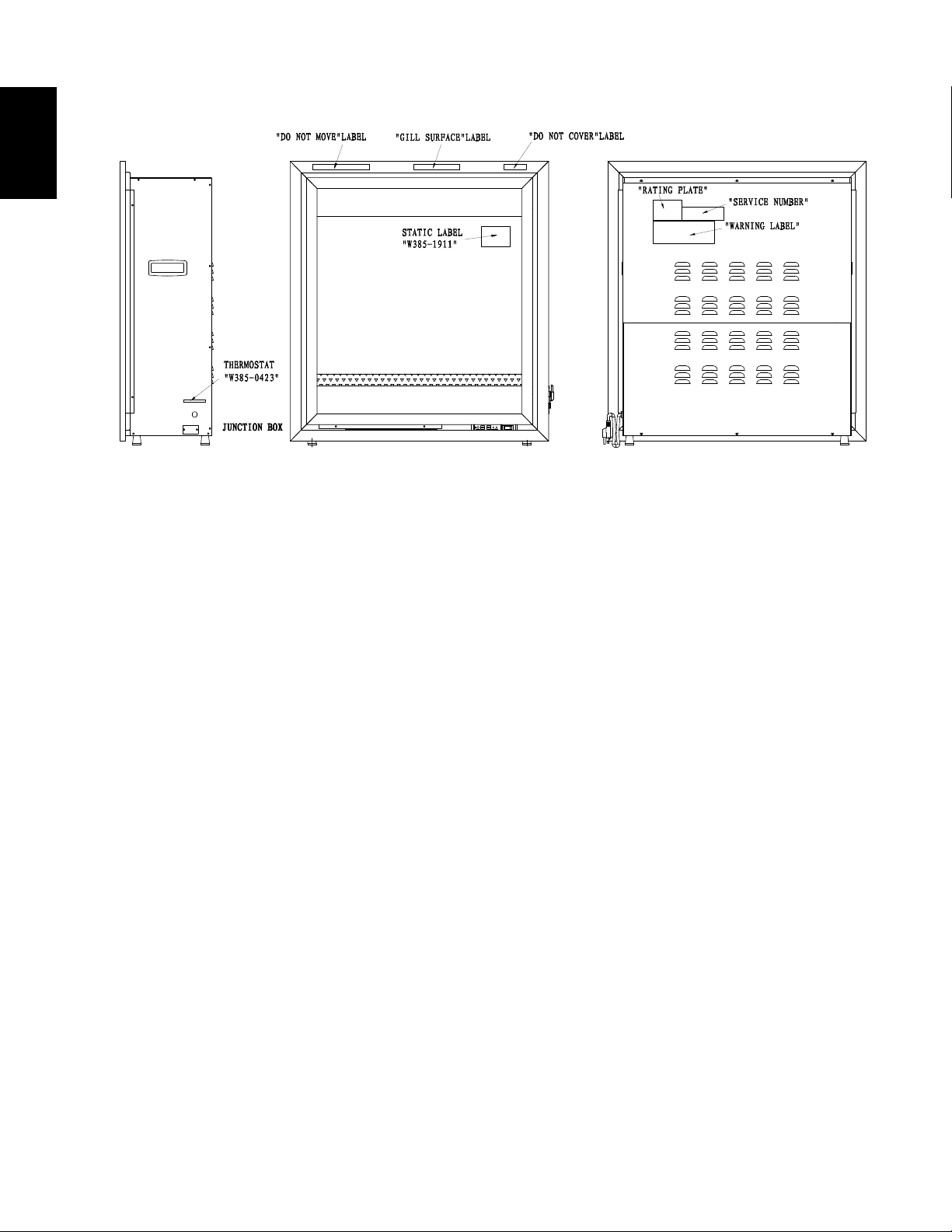
1.4 LABEL LOCATION
W415- 2166 / A / 06.29.16
Page 7
2.0 LOCATING APPLIANCE
WARNING
TO PREVENT CONTACT WITH SAGGING OR LOOSE INSULATION, THE ELECTRIC APPLIANCE MUST
7
!
DUE TO HIGH TEMPERATURES, THIS ELECTRIC APPLIANCE SHOULD BE LOCATED OUT OF
TRAFFIC. KEEP COMBUSTIBLE MATERIALS SUCH AS FURNITURE, PILLOWS, BEDDING, PAPERS,
CLOTHES AND CURTAINS AT LEAST 3 FEET (0.9M) FROM THE FRONT OF THE APPLIANCE.
NEVER LOCATE THIS ELECTRIC APPLIANCE WHERE IT MAY FALL INTO A BATHTUB OR OTHER
WATER CONTAINER.
WEAR SAFETY GLOVES AND SAFETY GLASSES FOR PROTECTION DURING INSTALLATION AND
MAINTENANCE.
NOT BE INSTALLED AGAINST VAPOR BARRIER OR EXPOSED INSULATION. LOCALIZED
OVERHEATING COULD OCCUR AND A FIRE COULD RESULT.
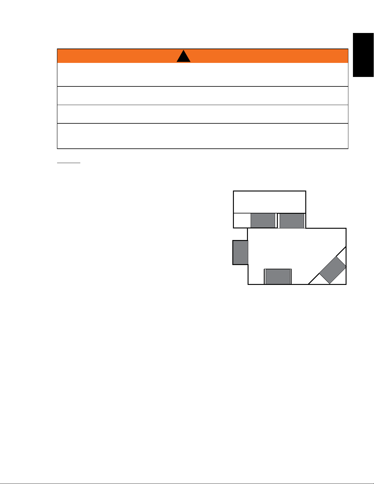
NOTICE
Minimum clearance of 1" on all sides, back and top must
be maintained at all times. Illustrations throughout these
instructions reflect typical installations and are for design
purposes only. Actual installations may vary slightly due to
individual preferences.
Illustrates a variety of ways the appliance may be located
in a room. The appliance may be installed directly on the
floor (uncarpeted), or raised on a hearth.
TOP VIEW SHOWING APPROVED ROOM
LOCATIONS OF APPLIANCE
EN
2.1 UNPACKING AND TESTING APPLIANCE
Carefully remove the appliance from the box. Prior to installing the appliance, test to make sure the appliance
operates properly by plugging the power supply cord into a conveniently located 120 Volt grounded outlet.
W415-2166 / A / 06.29.16
Page 8
8
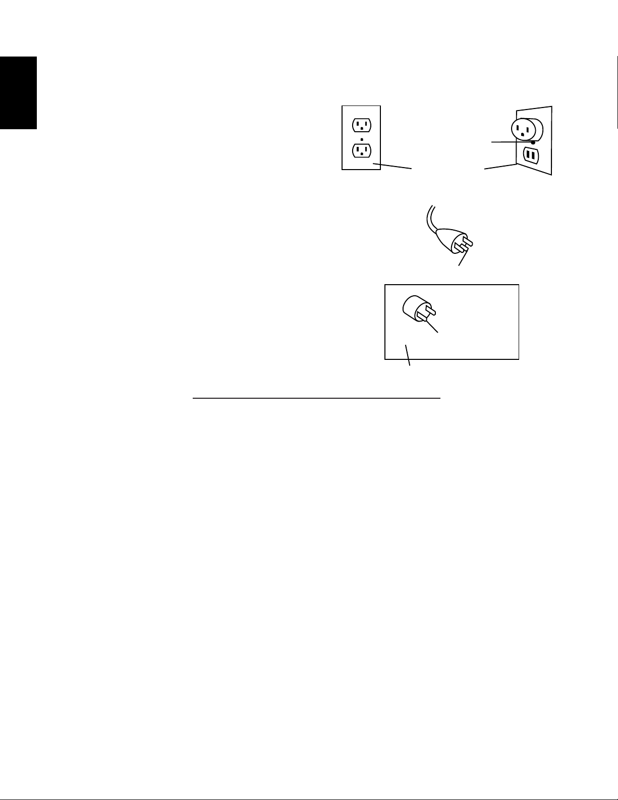
This appliance is for use on 120 volts. The cord has a plug
as shown in (A). An adapter as shown in (C) is available for
connecting three-blade grounding type plugs to two-slot
receptacles. The green grounding plug extending from the
adapter must be connected to a permanent ground such as
a properly grounded outlet box. The adapter should not be
used if a three-slot grounded receptacle is available.
To disconnect appliance, turn controls to off, then remove
plug from outlet.
2.2 GROUNDING APPLIANCE
EN
GROUNDING METHODS
METAL SCREW
(A)
NOT ALLOWED IN CANADA
COVER OF
GROUNDED
OUTLET BOX
GROUNDING PIN
(C)
GROUNDING
(B)
ADAPTER
MEANS
96.1
W415- 2166 / A / 06.29.16
Page 9
3.0 INSTALLATION
WARNING
SION MAY RESULT CAUSING PROPERTY DAMAGE, PERSONAL INJURY OR DEATH. DO NOT STORE
APPLIANCE VENTS LOCATED ON THE FRONT AND BACK OF THIS ELECTRIC APPLIANCE CANNOT,
9
!
RISK OF FIRE! THE POWER CORD MUST NOT BE PINCHED AGAINST A SHARP EDGE. SECURE
CORD TO AVOID TRIPPING OR SNAGGING TO REDUCE THE RISK OF FIRE, ELECTRIC SHOCK OR
PERSONAL INJURY. DO NOT RUN CORD UNDER CARPETING. DO NOT COVER CORD WITH THROW
RUGS, RUNNERS OR THE LIKE. ARRANGE CORD AWAY FROM TRAFFIC AREAS AND WHERE IT
WILL NOT BE TRIPPED OVER.
RISK OF FIRE! TO PREVENT A POSSIBLE FIRE, DO NOT BLOCK AIR INTAKE OR EXHAUST IN ANY
MANNER. DO NOT USE ON SOFT SURFACES WHERE OPENINGS MAY BECOME BLOCKED.
RISK OF FIRE! DO NOT BLOW OR PLACE INSULATION AGAINST THE APPLIANCE.
THIS ELECTRIC APPLIANCE IS TESTED AND LISTED FOR USE ONLY WITH THE APPROVED
OPTIONAL ACCESSORIES. USE OF OPTIONAL ACCESSORIES NOT SPECIFICALLY TESTED FOR
THIS ELECTRIC APPLIANCE COULD VOID THE WARRANTY AND/OR RESULT IN A SAFETY HAZARD.
IF THE INFORMATION IN THESE INSTRUCTIONS IS NOT FOLLOWED EXACTLY, A FIRE OR EXPLO-
OR USE GASOLINE OR OTHER FLAMMABLE VAPORS IN THE VICINITY OF THIS OR ANY OTHER
APPLIANCE.
THIS APPLIANCE MUST REMAIN REMOVABLE FROM THE ENCLOSURE. THE APPLIANCE MAY BE
HARD WIRED, BUT IT IS RECOMMENDED THAT IT BE PLUGGED INTO A STANDARD OUTLET USING
THE SUPPLIED POWER CORD. THIS APPLIANCE MUST NOT BE SEALED AROUND THE FRONT
FACING.
EN
IN ANY WAY, BE COVERED AS IT MAY CREATE A FIRE HAZARD.
BEFORE INSTALLATION
Select a suitable location that is not susceptible to moisture and is away from drapes, furniture and high
traffic areas. NOTE: Follow all national and local electrical codes. This appliance can be installed into
either an existing fireplace opening or as new construction / renovation.
EXISTING APPLIANCE INSTALLATION
Thoroughly clean out the existing fireplace and hearth area.
Plan the power supply. If an existing grounded outlet is near the appliance, the power cord can run behind
the appliance. If the cord is not long enough to reach the outlet, a grounded extension cord minimum AWG
No. 14 and rated to a minimum of 1875 watts may be used. If you plan to cut or drill a hole in the existing
fireplace for wiring, it is best to hire a professional to do this step in order to prevent personal injury. To reduce
the risk of fire, do not run the power cord under rugs, carpets, etc. Arrange the power supply cord away from
high traffic areas where it may pose a tripping hazard.
W415-2166 / A / 06.29.16
Page 10
10
WARNING
3.1 MINIMUM CLEARANCE TO COMBUSTIBLES
EN
THIS APPLIANCE MUST REMAIN REMOVABLE FROM THE ENCLOSURE. THE APPLIANCE MAY BE HARD
WIRED, BUT IT IS RECOMMENDED THAT IT BE PLUGGED INTO A STANDARD OUTLET USING THE
SUPPLIED POWER CORD. THIS APPLIANCE MUST NOT BE SEALED AROUND THE FRONT FACING.
APPLIANCE VENTS LOCATED ON THE FRONT AND BACK OF THIS ELECTRIC APPLIANCE CANNOT,
IN ANY WAY, BE COVERED AS IT MAY CREATE A FIRE HAZARD.
Sides, back, top 1" (25mm)
3.2 MINIMUM MANTEL CLEARANCES
RISK OF FIRE, MAINTAIN ALL SPECIFIED AIR SPACE CLEARANCES TO COMBUSTIBLES. FAILURE
TO COMPLY WITH THESE INSTRUCTIONS MAY CAUSE A FIRE OR CAUSE THE APPLIANCE TO
OVERHEAT. ENSURE ALL CLEARANCES (I.E. BACK, SIDE, TOP, VENT, MANTEL, FRONT, ETC.) ARE
WHEN USING PAINT OR LACQUER TO FINISH THE MANTEL, THE PAINT OR LACQUER MUST BE
HEAT RESISTANT TO PREVENT DISCOLOURATION.
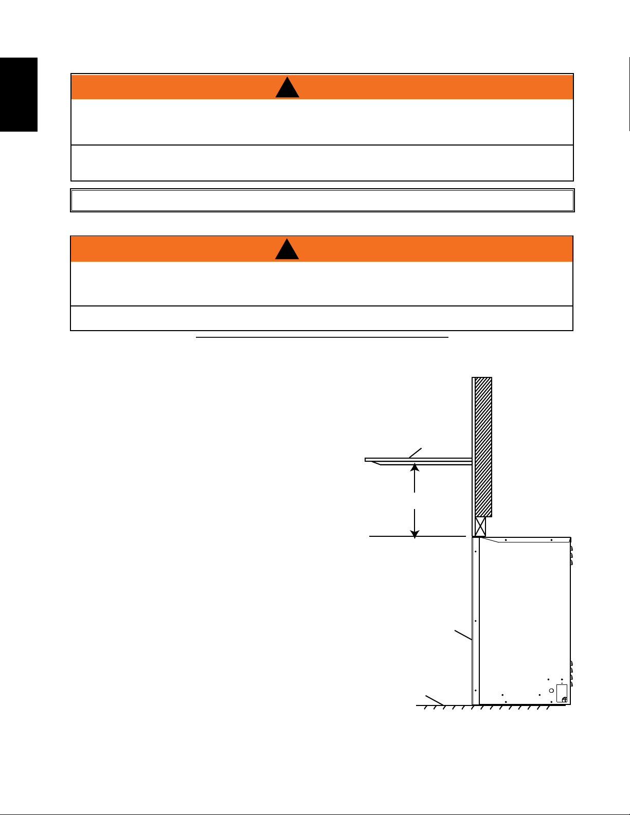
The minimum distance from the top of the appliance that the mantel can be installed is 10" (254mm), at any depth.
!
WARNING
!
CLEARLY MAINTAINED.
73.1
MANTEL
10”
FRONT
GLASS
OPTIONAL
HEARTH
WALL
APPLIANCE
SIDEVIEW
W415- 2166 / A / 06.29.16
Page 11
3.3 NEW CONSTRUCTION OR RENOVATION
A. Select a location that is not prone to moisture and is located at least 0.9 m or 3 feet away from
combustible materials such as curtains or drapes, furniture, bedding, paper, etc.
B. Place the appliance in selected location to see how it will look in the future.
C. Mark the desired location on the floor and store appliance in a safe, dry and dust free location.
D. Frame in an opening leaving at least 1/4" (6 mm) around the edge of the appliance. Any new wiring
must be done in compliance with local and national codes and other applicable regulations in order
to reduce the risk of fire, electric shock or other injuries. Therefore, it is strongly recommended that
you hire a professional to complete any such work.
3.4 INSTALLING THE APPLIANCE
A. Once the site has been prepared, the appliance can be installed.
B. Make sure the main power switch is in the "OFF" position.
C. Plug the appliance into a 15-amp/120 Volt, grounded outlet. Use a CSA or UL approved surge
protector.
D. Push in the appliance so that the trim is against the finished mantel or wall surface.
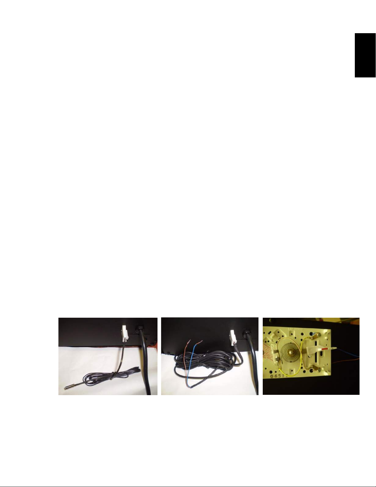
3.5 THERMOSTAT AND THERMAL SENSOR INSTALLATION
This appliance has two options for heat control.
11
EN
First is a thermal controlled sensor, which comes plugged into the appliance beside the main power cord.
This sensor has no user temperature set points, it will turn off the heater when the sensor reaches its pre-set
point, and will only turn the heater back on when it has cooled back down below this set point. On the low
setting (green light) the set point is 16°C/61°F, on medium (orange light) 22°C/72°F and on high (red light)
28°C/82°F. This small sensor can be placed anywhere in the room within the length of the sensor wire, but it
should not be placed near the top or front of the appliance. Placing the sensor too close to the heater area of
the appliance will cause unwanted cycling of the heater.
Second is the option of a wall-mounted thermostat. Napoleon Part # W690-0001, W660-0081, or an equivalent low voltage thermostat.
A wall thermostat can be used in place of the thermal control sensor. You must first remove the sensor by unplugging it from the right side of the appliance beside the main power cord. Replace the sensor with the wire
harness provided in the manual baggie. Plug it into the appliance and connect the other end to the thermostat. The thermostat should be placed as per the thermostat installation instructions.
W680-0022
Thermo-controlled sensor
5M Temperature Probe (included)
W415-2166 / A / 06.29.16
Page 12
12
WARNING
3.6 HARDWIRE INSTALLATION
EN
TURN OFF THE APPLIANCE COMPLETELY AND LET COOL BEFORE SERVICING. ONLY A QUALIFIED
SERVICE PERSON SHOULD SERVICE AND REPAIR THIS ELECTRIC APPLIANCE.
HARDWIRING CONNECTION
If it is necessary to hardwire this appliance, a qualified electrician may remove the cord connection, and wire
the appliance directly to the house hold wiring.
This appliance must be electrically connected and grounded in accordance with local codes, if hardwired. In
the absence of local codes, use the current CSA C22.1 CANADIAN ELECTRICAL CODE in Canada or the current ANSI/NFPA 70 NATIONAL ELECTRICAL CODE in the United States.
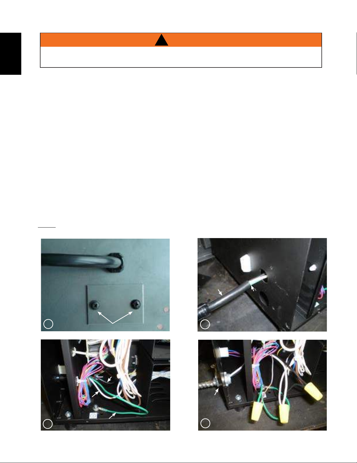
A. Remove cover plate located beside the power cord to reveal the 7/8” wire hole. Discard cover plate,
screws and insert a box connector into the hole.
B. Remove the lower back panel from the appliance to expose wiring.
C. Remove the power cord strain-relief from the side of the appliance and cut the cord where shown
below. This will be the hardwire connection point.
D. Feed the supply wires through the box connector and the grommet.
E. Using wire connectors connect the common (white) wires together, then the hot (black) wires, and
then the ground (green) wires.
F. Ensure the newly connected wires are kept away from the rotating parts and the circuit board, and
re-install the back panel.
!
NOTE: This appliance must be serviced from the back, leave enough wire so that the appliance can be
removed from the enclosure without disconnecting the power supply wires.
Power Cord
Cut
1
Remove 2 screws on cover plate.
Hot Wire
3
Common Wire
2
W415- 2166 / A / 06.29.16
Ground Wire
Box
Connector
4
Final Connection
Page 13
CEILING LIGHT
N
L1
G
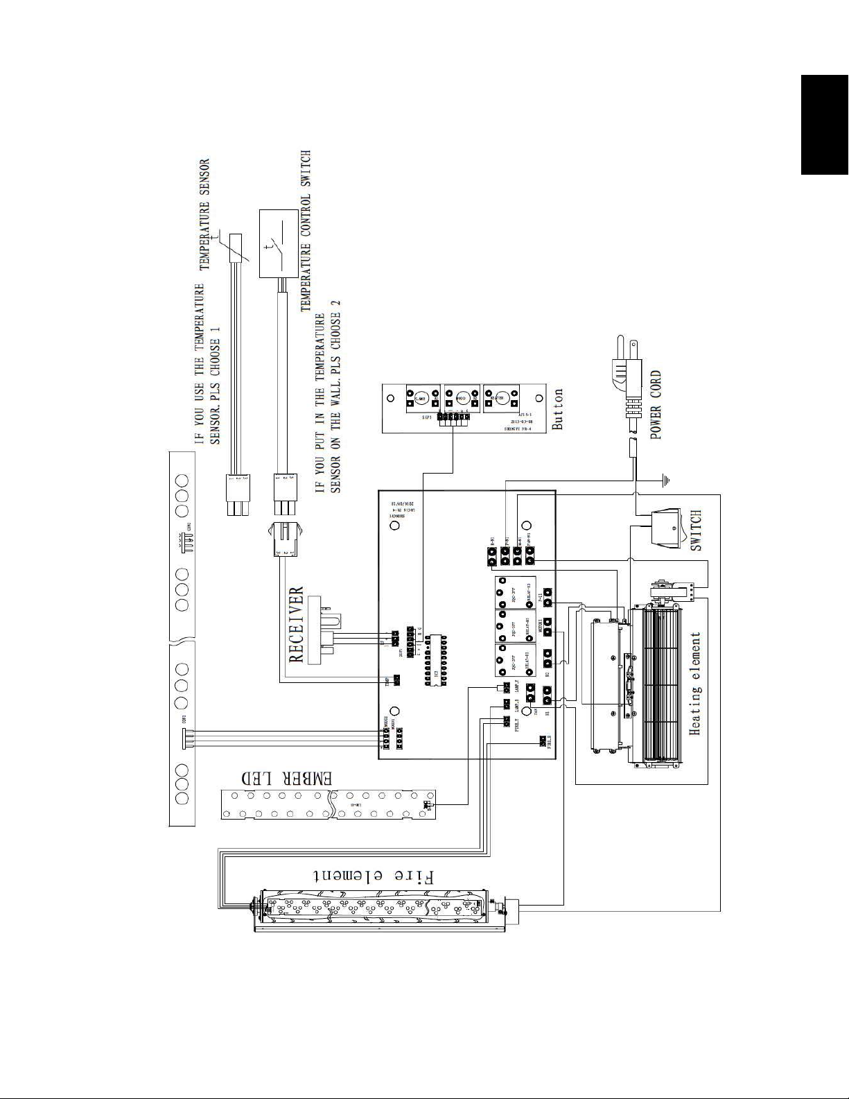
3.7 WIRING DIAGRAM
13
EN
W415-2166 / A / 06.29.16
Page 14
EN
WARNING
14
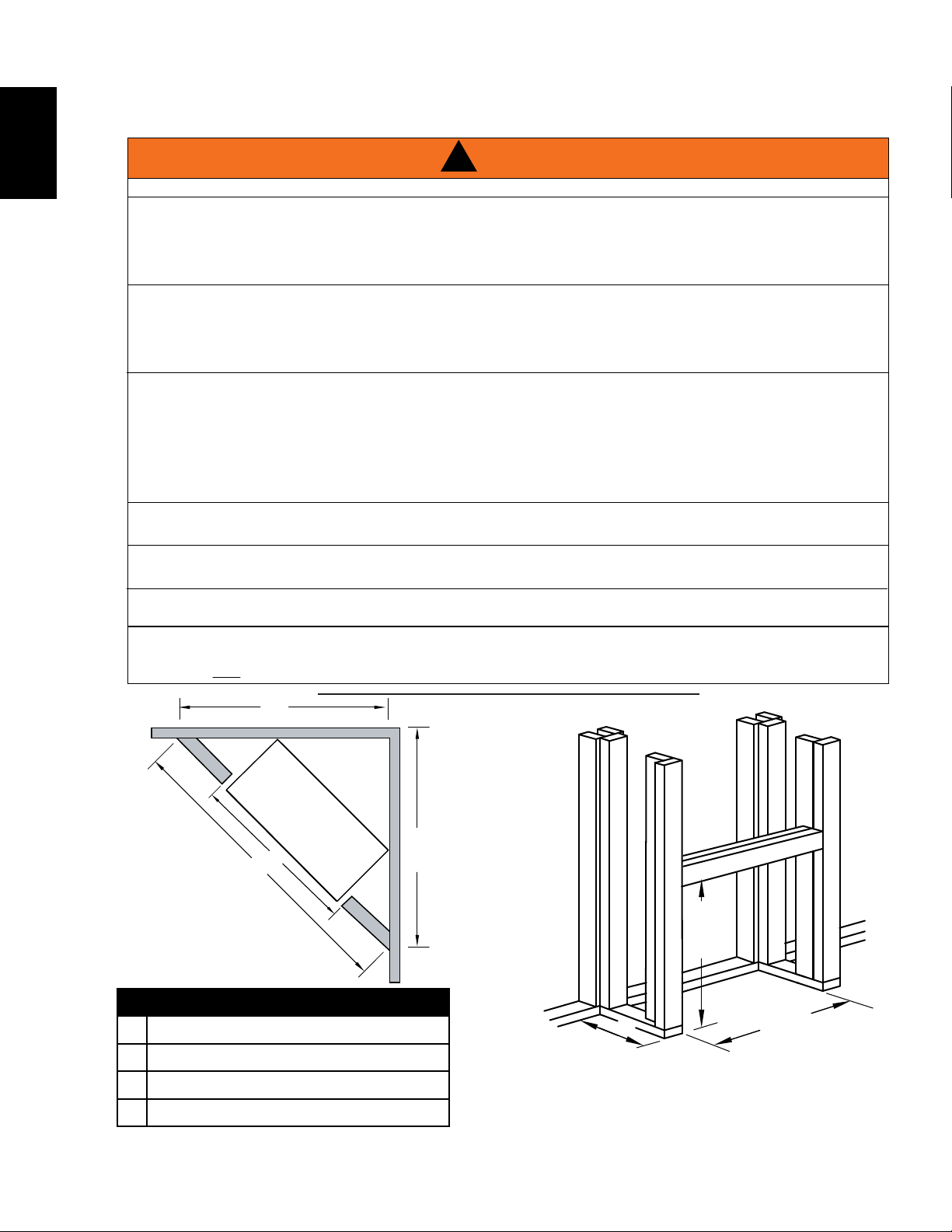
4.0 FRAMING
IN ORDER TO AVOID THE POSSIBILITY OF EXPOSED INSULATION OR VAPOUR BARRIER COMING
IN CONTACT WITH THE APPLIANCE BODY, IT IS RECOMMENDED THAT THE WALLS OF THE
APPLIANCE ENCLOSURE BE “FINISHED” (IE: DRYWALL / SHEETROCK), AS YOU WOULD FINISH
ANY OTHER OUTSIDE WALL OF A HOME. THIS WILL ENSURE THAT CLEARANCE TO
DO NOT NOTCH THE FRAMING AROUND THE APPLIANCE STAND-OFFS. FAILURE TO MAINTAIN
AIR SPACE CLEARANCE MAY CAUSE OVER HEATING AND FIRE. PREVENT CONTACT WITH
SAGGING OR LOOSE INSULATION OR FRAMING AND OTHER COMBUSTIBLE MATERIALS. BLOCK
OPENING INTO THE CHASE TO PREVENT ENTRY OF BLOWN-IN INSULATION. MAKE SURE
WHEN CONSTRUCTING THE ENCLOSURE ALLOW FOR FINISHING MATERIAL THICKNESS TO
MAINTAIN CLEARANCES. FRAMING OR FINISHING MATERIAL CLOSER THAN THE MINIMUMS
LISTED MUST BE CONSTRUCTED ENTIRELY OF NON-COMBUSTIBLE MATERIALS. MATERIALS
CONSISTING ENTIRELY OF STEEL, IRON, BRICK, TILE, CONCRETE, SLATE, GLASS OR PLASTERS,
OR ANY COMBINATION THEREOF ARE SUITABLE. MATERIALS THAT ARE REPORTED AS PASSING
ASTM E 136, STANDARD TEST METHOD FOR BEHAVIOUR OF MATERIALS IN A VERTICAL TUBE
FURNACE AT 1382° F (750°C) AND UL763 SHALL BE CONSIDERED NON-COMBUSTIBLE
MINIMUM CLEARANCE TO COMBUSTIBLES MUST BE MAINTAINED OR A SERIOUS FIRE HAZARD
THE APPLIANCE REQUIRES A MINIMUM ENCLOSURE HEIGHT. MEASURE FROM THE APPLIANCE
IF STEEL STUD FRAMING KITS WITH CEMENT BOARD ARE PROVIDED, OR SPECIFIED IN THE
IF SPECIFIED IN THE INSTALLATION INSTRUCTION FINISHING MUST BE DONE USING A NON-
COMBUSTIBLE MATERIAL SUCH AS NON-COMBUSTIBLE BOARD, CERAMIC TILE, MARBLE, ETC.
DO NOT USE WOOD OR DRYWALL. ANY FIRE RATED DRYWALL IS NOT ACCEPTABLE
!
RISK OF FIRE!
COMBUSTIBLES IS MAINTAINED WITHIN THE CAVITY.
INSULATION AND OTHER MATERIALS ARE SECURED.
MATERIALS.
COULD RESULT.
BASE.
INSTALLATION INSTRUCTIONS, THEY MUST BE INSTALLED.
K
71.1C
B
J
K
L
W415- 2166 / A / 06.29.16
B
J
NEFB30GL
29" (737mm)
50" (1270mm)
35 3/8" (898mm)
35 3/8" (898mm)
L
H
R
E
AD
E
31 1/2"
[800mm]
29"
11 3/4"
[737mm]
[298mm]
Page 15
5.0 FINISHING
15
NEVER OBSTRUCT THE FRONT OPENING OF THE APPLIANCE.
DO NOT STRIKE, SLAM OR SCRATCH GLASS. DO NOT OPERATE APPLIANCE WITH GLASS
REMOVED, CRACKED, BROKEN OR SCRATCHED.
FACING AND/OR FINISHING MATERIAL MUST NEVER OVERHANG INTO THE APPLIANCE OPENING.
5.1 HEARTH
A hearth is NOT necessary but is recommended for aesthetic purposes.
5.2 COLD CLIMATE INSTALLATION
IT IS MANDATORY TO HAVE AN INSULATED WALL BEHIND THE APPLIANCE, WHEN THE
APPLIANCE IS BEING INSTALLED ON AN OUTSIDE WALL OR CHASE.
5.3 FINISHING CHECKLIST
A. Power supply service must be completed prior to finishing to avoid reconstruction.
B. Appliance vents and air openings cannot be covered in any circumstances.
!
WARNING
RISK OF FIRE!
!
WARNING
EN
W415-2166 / A / 06.29.16
Page 16
16
HIGH LOW TEMP OFF
High
Brightness
Medium
Brightness
Low
Brightness
Light off
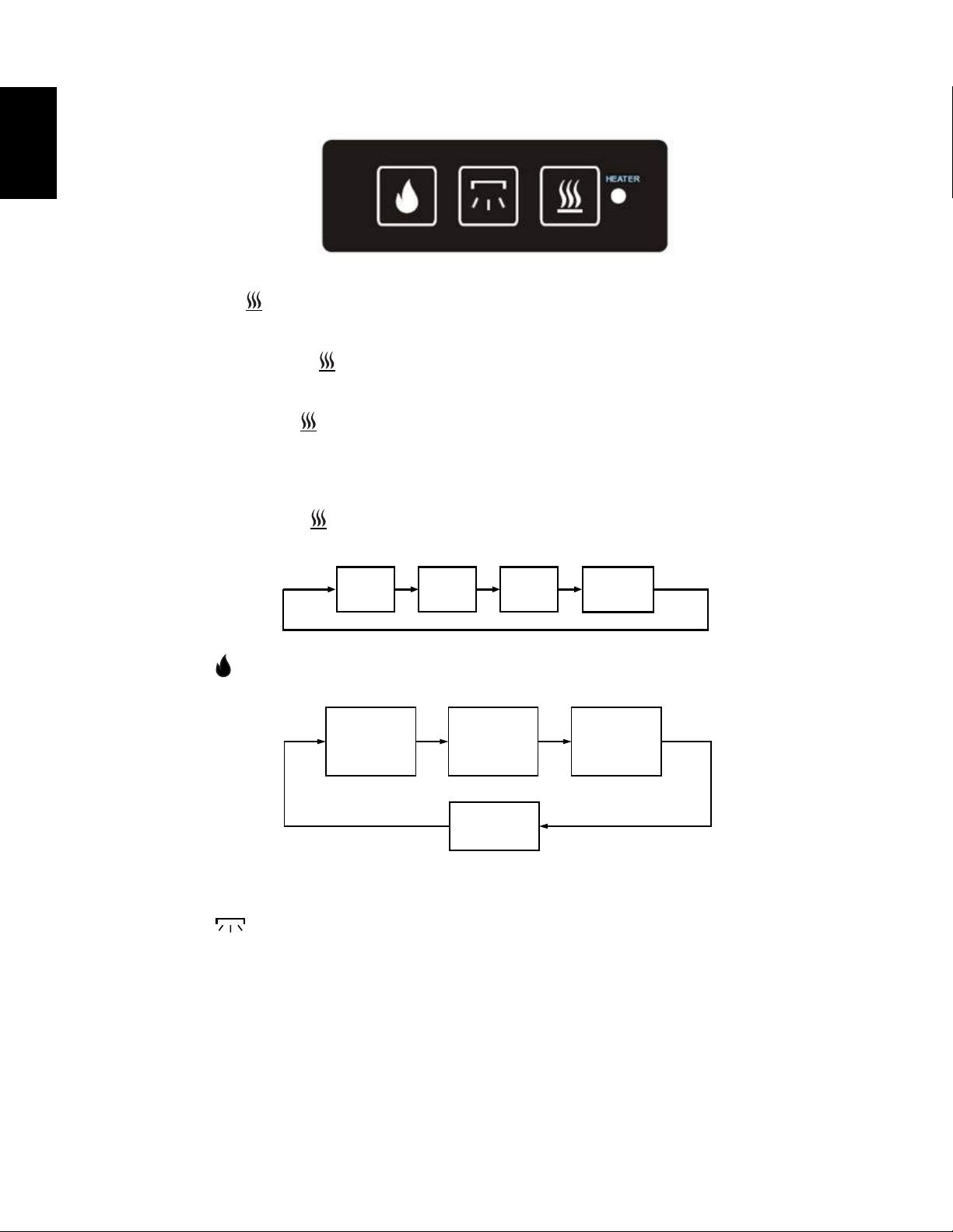
6.0 OPERATING INSTRUCTIONS
EN
After turning the power switch on, the power indicator is red.
First press of the "
simultaneously while the power is 1500W, indicator is red.
Second press of the button "
work while the power is 750W, indicator is blue.
Third press of the button "
appliance automatically sets the room temperature as 25°C. When the room temperature is above 25°C, the
heating element shuts off. When the room temperature is below 22°C, the heating element starts working at
1500W. When the room temperature is between 22-25°C, the heating element starts working at 750W.
Fourth press of the button "
Press button "
" button : the heating element is on "HIGH" mode, two groups of heating elements work
": the heating element is on "LOW" mode, one group of heating elements
": the heating element is on "TEMP" mode. When "TEMP" mode is on, the
": turns off the heating element.
": flame and ember bed work simultaneously in the following sequence:
Press button "
blue light. The second to fourth press switches lights in sequence of blue, amber and yellow. The fifth press
switches the light to a combination of blue, yellow and amber light. The sixth press shuts off the lights.
W415- 2166 / A / 06.29.16
": the ceiling light is switched on. The first press gradually increases the brightness of
Page 17

6.1 OPERATING BY REMOTE CONTROL
Blue Amber Yellow Blinking Switch off
1. Plug in the power cord and turn on the power switch. You will hear the buzzer make
two beep sounds, indicating that the power is turned on. Press the "
up the appliance. Flame and ember bed LEDs will turn on with the brightness level set
to the highest as the default, the heating element will be off and the ceiling light will
turn on the color starting to change gradually from bright blue.
2. The “ ” button is the switch for entire appliance, when the appliance is turned off,
press “
been turned off. When the appliance is turned on, press “
powers off; the ember bed, flame, heating element and background light are turned
off. The other function buttons listed as following can only work under the condition
that the “
level of the flame and ember bed LED are set to highest when “
on the appliance.
”; the appliance is turned on with the same setting as the last time it has
” button, the appliance
” is on. If the flame is off when the appliance is turned off, the brightness
” is pressed to turn
17
" key to start
EN
3. Button "
and the light of the flame and ember bed will turn off. When the flame and ember bed
LEDs are off, press the button to turn on the flame and ember bed LEDs.
4. Yellow button “
the brightness level changes with each press until you turn the light off completely;
press the button again to repeat the cycle.
5. Blue button “
with each press until you turn the light off completely; press the button again to repeat the cycle.
6. Pink button “
with each press until you turn the light off completely; press the button again to repeat the cycle.
7. Ember button “
with each press until you turn the light off completely; press the button again to repeat the cycle.
8. Button “ ”, press this button to turn on the heating element. The heating element starts to work on
“HIGH” mode with the power at 1500W; press the button again to turn off the heating element.
9. Button “
and the heating element starts to work on “HIGH” mode (1500W). Press again to repeat the cycle change.
": When the flame and ember bed LEDs are turned on, press the button,
” controls the six brightness levels of the yellow LED flame lights;
”, controls the six brightness levels of the blue LED flame lights; the brightness level changes
”, controls the six brightness levels of the pink LED flame lights; the brightness level changes
”, controls the six brightness levels of ember bed LED lights; the brightness level changes
”, press this button and the heating element starts to work on “LOW” mode (750W), press again
10. Button “
room temperature at 25°C. When the room temperature is above 25°C, the heating element shuts off. When
the room temperature is below 22°C, the heating element starts working at 1500W. When the room temperature is between 22-25°C, the heating element starts working at 750W.
Caution: “HIGH” “LOW” “TEMP” buttons only work under the condition when “
When the appliance is on “HIGH” or “LOW” mode, the heating element is turned on all the time and the
thermostat will not work.
11. Button “
”, press this to start TEMP mode. When "TEMP mode is on, the appliance automatically sets the
” controls the ceiling light. Below shows the work mode of the ceiling light:
” is in the on position.
NOTE: Make sure your batteries are
fully charged and installed correctly
in your remote control.
W415-2166 / A / 06.29.16
Page 18

18
FRONT PLATE
UNSCREW LOGSET
Front View of Appliance
PLACE CRYSTALS
2 Screws
2 Screws
UNHOOK INNER FRAME
PLACE CRYSTALS
WARNING
6.2 CRYSTAL EMBER PLACEMENT
EN
TURN OFF THE APPLIANCE COMPLETELY AND LET COOL BEFORE SERVICING. ONLY A QUALIFIED
SERVICE PERSON SHOULD SERVICE AND REPAIR THIS ELECTRIC APPLIANCE.
1. Unscrew the two screws at the bottom of the front plate.
2. Unhook and lift off the frame of the inner surface and
place carefully on a safe work surface.
3. Unscrew the two screws on the ember tray with a screwdriver.
4. Remove the logset and put the crystals in.
5. Re-install the frame of the inner surface.
!
W415- 2166 / A / 06.29.16
Page 19

6.3 LED / REMOTE RECEIVER / THERMOSTAT REPLACEMENT
WARNING
19
!
TURN OFF THE APPLIANCE COMPLETELY AND LET COOL BEFORE SERVICING. ONLY A QUALIFIED
SERVICE PERSON SHOULD SERVICE AND REPAIR THIS ELECTRIC APPLIANCE.
1. To replace LED lights in the ember bed, flame and/or decorative lights, disconnect the quick connect plug
from the control board and replace with a new one.
2. To replace the remote receiver and thermostat wires, disconnect the quick connect plug from the control
board and replace with a new one.
L
E
N
A
P
L
O
R
T
N
O
C
R
E
IV
E
C
E
R
E
T
O
M
E
R
T
A
T
S
O
M
R
E
H
T
T
H
IG
L
P
O
T
EN
D
E
L
E
M
A
L
F
E
D
E
L
G
O
/ L
D
E
B
R
E
B
M
6.4 FUSE REPLACEMENT
1. Remove the plastic cover from the fuse. Pull the fuse (2Amp) out from the control board. Install the replacement fuse and plastic cover.
R
E
V
O
C
E
S
U
F
W415-2166 / A / 06.29.16
Page 20

20
Contact your dealer for questions concerning prices and policies on replacement parts. Normally, all parts
can be ordered through your Authorized dealer / distributor.
FOR WARRANTY REPLACEMENT PARTS, A PHOTOCOPY OF THE ORIGINAL INVOICE WILL BE
REQUIRED TO HONOUR THE CLAIM.
When ordering replacement parts always give the following information:
PARTS, PART NUMBERS AND AVAILABILITY ARE SUBJECT TO CHANGE WITHOUT NOTICE.
PARTS IDENTIFIED AS STOCKED WILL BE DELIVERED WITHIN 2 TO 5 BUSINESS DAYS FOR MOST
DELIVERY DESTINATIONS.
PARTS NOT IDENTIFIED AS STOCKED WILL BE DELIVERED WITHIN A 2 TO 4 WEEK PERIOD, FOR
MOST CASES.
PARTS IDENTIFIED AS ‘SO’ ARE SPECIAL ORDER AND CAN TAKE UP TO 90 DAYS FOR DELIVERY.
WARNING
7.0 REPLACEMENT PARTS
EN
FAILURE TO POSITION THE PARTS IN ACCORDANCE WITH THIS MANUAL OR FAILURE TO USE
ONLY PARTS SPECIFICALLY APPROVED WITH THIS APPLIANCE MAY RESULT IN PROPERTY
Model & Serial Number of appliance
Installation date of appliance
Part number
Description of part
Finish
!
DAMAGE OR PERSONAL INJURY.
41.1C
For after sales service, please call 1-866-820-8686
COMPONENTS
REF # PART # DESCRIPTION STOCKED
1
2
3
4
5
6
7
8
9
10
11
12
13
14
15
16
REF # PART # DESCRIPTION
17*
18*
W415- 2166 / A / 06.29.16
W300-0178 (540G) CRYSTAL YES
W300-0246 LARGE DECORATIVE CRYSTAL YES
W190-0109 CIRCUIT BOARD YES
W010-3966 HEATER AND BLOWER ASSEMBLY YES
W660-0128 MAIN POWER SWITCH YES
W190-0110 REMOTE CONTROL YES
W405-0043 EMBER BED LED YES
GBL38-001.02-00 FRONT GLASS PANEL YES
GBL38-000-07 MIRROR GLASS YES
W010-3965 DRUM ASSEMBLY YES
W660-0129 REMOTE RECEIVER YES
W080-1719 MEDIA TRAY SO
W435-0080 DRUM MOTOR YES
W285-0006 FUSE YES
W135-0646 LOG SET YES
W680-0022 THERMO-CONTROLLED SENSOR YES
ACCESSORIES
W660-0081 DIGITAL THERMOSTAT
W690-0001 MILLIVOLT THERMOSTAT
Page 21

4
1
2
3
7
6
8
9
14
13
12
15
16
10
5
11
7.1 REPLACEMENT PARTS DIAGRAM
NOTE: Care must be taken when removing and disposing of any broken glass or damaged components. Be sure to vacuum up any broken glass from inside the appliance before operation.
21
EN
W415-2166 / A / 06.29.16
Page 22

22
WARNING
8.0 TROUBLESHOOTING
EN
!
TURN OFF THE APPLIANCE COMPLETELY AND LET COOL BEFORE SERVICING. ONLY A
QUALIFIED SERVICE PERSON SHOULD SERVICE AND REPAIR THIS ELECTRIC APPLIANCE.
SYMPTOM PROBLEM TEST SOLUTION
Dim or no fl ame Light bulb(s) / LED light(s)
are not lit
Ember bed is not
glowing or dimming
No warm air coming
out of appliance
Appliance turns off
and will not turn on
Appliance will not
come on when
switch is fl ipped to
ON
Remote control
does not work
Heater shuts off
automatically
Light bulb(s) / LED light(s)
are not lit
Room temperature is higher
than the appliance setting (if
it is set to LO or MED)
Appliance has overheated
and safety device has
caused the thermal switch to
disconnect
House circuit breaker has
tripped
Appliance is not plugged
into an electrical outlet
Appliance has overheated
and safety device has
caused the thermal switch to
disconnect
Low batteries Replace batteries in remote control
Room is too warm The heater has a built-in thermostat so it will shut off automati-
Inspect the lights inside the fl ame generation space and replace
them if necessary
Inspect the ember bed lights and replace them if necessary
Set appliance to a higher temperature setting (MED or HI)
Unplug the appliance, allow appliance to cool for 15 minutes,
then plug it back in
Reset house circuit breaker
Check plug and plug it in
Unplug the appliance, allow appliance to cool for 15 minutes,
then plug it back in
cally once the pre-set temperature is reached. It will also turn on
automatically if the room temperature drops below the pre-set
temperature
42.23C
W415- 2166 / A / 06.29.16
Page 23

9.0 WARRANTY
NAPOLEON electric appliances are manufactured under the strict Standard of the world recognized
23
ISO 9001 : 2008 Quality Assurance Certifi cate.
NAPOLEON products are designed with superior components and materials and assembled by trained craftsmen who
take great pride in their work. Once assembled the complete appliance is thoroughly inspected by a qualifi ed technician
before packing to ensure that you, the customer, receive the quality product that you expect from NAPOLEON.
NAPOLEON ELECTRIC APPLIANCE LIMITED WARRANTY
Electrical components and wearable parts are covered and NAPOLEON will provide replacement parts free of charge during
the fi rst year of limited warranty. This covers: fan/heaters, motors, switches, nylon bearing components, remote controls and
LED lights.
Any labour related to warranty repair is not covered.
* Construction of models vary. Warranty applies only to components included with your specifi c appliance.
NAPOLEON warrants its products against manufacturing defects to the original purchaser only. Registering your warranty is not necessary.
Simply provide your proof of purchase along with the model and serial number to make a warranty claim. NAPOLEON reserves the right to have
its representative inspect any product or part thereof prior to honouring any warranty claim. Provided that the purchase was made through an
authorized NAPOLEON dealer, your appliance is subject to the following conditions and limitations:
Warranty coverage begins on the date of original installation.
This factory warranty is non-transferable and may not be extended whatsoever by any of our representatives.
Installation must be done in accordance with the installation instructions included with the product and all local and national building and fi re codes.
This limited warranty does not cover damages caused by misuse, lack of maintenance, accident, alterations, abuse or neglect and parts installed
from other manufacturers will nullify this warranty.
This limited warranty further does not cover any scratches, dents, corrosion or discolouring caused by excessive heat, abrasive and chemical
cleaners nor chipping on porcelain enamel parts, mechanical breakage of PHAZER™ logs.
In the fi rst year only, this warranty extends to the repair or replacement of warranted parts which are defective in material or workmanship,
provided that the product has been operated in accordance with the operation instructions and under normal conditions.
NAPOLEON will not be responsible for installation, labour or any other expenses related to the reinstallation of a warranted part, and such
expenses are not covered by this warranty. Notwithstanding any provisions contained in the Limited Warranty, NAPOLEON’s responsibility under
this warranty is defi ned as above, and it shall not in any event extend to any incidental, consequential or indirect damages.
This warranty defi nes the obligations and liability of NAPOLEON with respect to the NAPOLEON electric appliance and any other warranties
expressed or implied with respect to this product; its components or accessories are excluded.
NAPOLEON neither assumes, nor authorizes any third party to assume, on its behalf, any other liabilities with respect to the sale of this product.
Any damages to appliance, brass trim or other component due to water, weather damage, long periods of dampness, condensation, damaging
chemicals or cleaners will not be the responsibility of NAPOLEON.
The bill of sale or copy will be required together with a serial number and a model number when making any warranty claims from your authorized
dealer. The warranty registration card must be returned within fourteen days to register the warranty.
NAPOLEON reserves the right to have its representative inspect any product or part thereof prior to honouring any warranty claim.
All parts replaced under the Limited Warranty Policy are subject to a single claim.
All parts replaced under the warranty will be covered for a period of 90 days from the date of their installation.
The manufacturer may require that defective parts or products be returned or that digital pictures be provided to support the claim. Returned
products are to be shipped prepaid to the manufacturer for investigation. If a product is found to be defective, the manufacturer will repair or
replace such defect.
Before shipping your appliance or defective components, your dealer must obtain an authorization number. Any merchandise shipped without
authorization will be refused and returned to sender.
Shipping costs are not covered under this warranty.
Additional service fees may apply if you are seeking warranty service from a dealer.
CONDITIONS AND LIMITATIONS
EN
ALL SPECIFICATIONS AND DESIGNS ARE SUBJECT TO CHANGE WITHOUT PRIOR NOTICE DUE TO ON-GOING PRODUCT IMPROVEMENTS.
NAPOLEON IS A REGISTERED TRADEMARK OF WOLF STEEL LTD.
2.5D
W415-2166 / A / 06.29.16
Page 24

24
10.0 SERVICE HISTORY
EN
W415- 2166 / A / 06.29.16
43.1
Page 25

11.0 NOTES
44.1
Page 26

Products
®
Other Napoleon
Fireplace Inserts • Charcoal Grills • Gas Fireplaces • Waterfalls • Wood Stoves
Heating & Cooling • Electric Fireplaces • Outdoor Fireplaces • Gas Grills
24 Napoleon Road, Barrie, Ontario, Canada L4M 0G8
214 Bayview Drive, Barrie, Ontario, Canada L4N 4Y8
103 Miller Drive, Crittenden, Kentucky, USA 41030
7200 Trans Canada Highway, Montreal, Quebec, Canada H4T 1A3
Fireplaces / Heating & Cooling call: 705-721-1212 • Grills call: 705-726-4278
napoleonproducts.com
Page 27

27
INSTALLATEUR : LAISSEZ CE MANUEL AVEC L’APPAREIL.
PROPRIÉTAIRE : CONSERVEZ CE MANUEL POUR CONSULTATION ULTÉRIEURE.
NE LAISSEZ PAS LES ENFANTS OU AUTRES INDIVIDUS À RISQUE SEULS À PROXIMITÉ DE L’APPAREIL
INSTRUCTIONS
D’INSTALLATION ET
D’OPÉRATION
HOMOLOGUÉ SELON LES NORMES NATIONALES CANADIENNES ET AMÉRICAINES CSA C22.2 No-46 / UL 1278.
NEFB30GL
FOYER ÉLECTRIQUE
FR
CONSIGNES DE SÉCURITÉ
!
AVERTISSEMENT
Si ces instructions ne sont pas suivies à
la lettre, un incendie pourraient s’ensuivre
causant des dommages matériels, des
blessures corporelles ou des pertes de vie.
- N’entreposez pas et n’utilisez pas d’essence
ou autres liquides et vapeurs infl ammables à
proximité de cet appareil ou tout autre appareil.
Wolf Steel Ltd., 24 Napoleon Rd., Barrie, ON, L4M 0G8 Canada /
103 Miller Drive, Crittenden, Kentucky , USA, 41030
Téléphone 705-721-1212 • Télécopieur 705-720-9081 • www.napoleonfoyers.com • hearth@napoleonproducts.com
10,00 $
1.16F
W415-2166 / A / 06.29.16
Page 28

FR
EN
28
TABLE DES MATIÈRES
1.0 INTRODUCTION 29
1.1 DIMENSIONS 30
1.2 HOMOLOGATIONS 30
1.3 INSTRUCTIONS GÉNÉRALES 31
1.4 EMPLACEMENT L'ÉTIQUETTE 32
2.0 EMPLACEMENT DE L'APPAREIL 33
2.1 DÉBALLAGE ET VÉRIFICATION DE L'APPAREIL 33
2.2 MISE À LA TERRE DE L'APPAREIL 34
3.0 INSTALLATION 35
3.1 MINIMUM CLEARANCE TO COMBUSTIBLES 36
3.2 DÉGAGEMENTS MINIMAUX DE LA TABLETTE 36
3.3 NOUVELLE MAISON ET RÉNOVATION 37
3.4 INSTALLATION DE L'APPAREIL 37
3.5 INSTALLATION DU THERMOSTAT ET DE LA SONDE THERMIQUE 37
3.6 BRANCHEMENT PAR CÂBLE 38
3.7 SCHÉMA DE CÂBLAGE 39
4.0 OSSATURE 40
5.0 FINITIONS 41
5.1 BASE DE PROTECTION 41
5.2 INSTALLATION DANS DES CLIMATS FROIDS 41
5.3 LISTE DE VÉRIFICATION 41
6.0 OPERATING INSTRUCTIONS 42
6.1 OPERATING BY REMOTE CONTROL 43
6.2 PLACEMENT DE VERRE CONCASSÉ 44
6.3 REMPLACEMENT DE THERMOSTAT / TELECOMMANDE / DEL 45
6.4 REMPLACEMENT DE FUSIBLE 45
7.0 RECHANGES 46
7.1 SCHÉMA DE RECHANGES 47
8.0 GUIDE DE DÉPANNAGE 48
9.0 GARANTIE 49
10.0 HISTORIQUE D'ENTRETIEN 50
11.0 NOTES 51
NOTE : Les changements autres que de nature éditoriale sont dénotés par une ligne verticale dans la
marge.
W415-2166 / A / 06.29.16
Page 29

1.0 INTRODUCTION
!
AVERTISSEMENT
• CET APPAREIL EST CHAUD LORSQU’IL FONCTIONNE ET PEUT CAUSER DE GRAVES BRÛLURES EN CAS DE
CONTACT.
• Ne faites pas fonctionner l’appareil avant d’avoir lu et compris les instructions d’utilisation. Ne pas respecter les
instructions pourrait causer un incendie ou des blessures corporelles.
• Risque de brûlures. L’appareil doit être éteint et refroidi avant d’effectuer l’entretien. Pour débrancher l’appareil, mettez
d’abord les boutons de contrôle à « OFF » puis retirez la fi che de la prise de courant.
• N’installez pas de composants endommagés ou incomplets ni des composants de substitution.
• Ne brûlez pas de bois ou autres matériaux dans cet appareil.
• Les jeunes enfants doivent être supervisés attentivement lorsqu’ils sont dans la même pièce que l’appareil. Les jeunes
enfants et autres personnes sont sujets aux brûlures accidentelles. Une barrière de protection est recommandée s’il
y a dans la maison des individus à risque. Afi n de restreindre l’accès à l’appareil, installez une barrière de protection
ajustable pour garder les jeunes enfants ou autres personnes à risque hors de la pièce et loin des surfaces chaudes.
• Les vêtements et autres matériaux combustibles ne doivent pas être posés sur l’appareil ou à proximité.
• En raison des températures élevées, l’appareil devrait être placé loin des endroits passants et loin des meubles et des
rideaux.
• Assurez-vous de disposer de mesures de sécurité adéquates pour empêcher les jeunes enfants de toucher aux
surfaces chaudes.
• Même lorsque l’appareil est éteint, la porte et l’écran demeureront chauds pendant un bon moment.
• Consultez votre détaillant local de foyer pour connaître les grillages de sécurité et les écrans offerts pour protéger les
enfants des surfaces chaudes. Ces grillages de sécurité et ces écrans doivent être fi xés au plancher.
• Les grillages de sécurité ou écrans enlevés pour faire l’entretien devront être remis en place avant d’utiliser l’appareil.
• Il est primordial de garder propres les compartiments de contrôle, la souffl erie et les bouches d’air de l’appareil.
L’appareil doit être inspecté avant la première utilisation et au moins une fois l’an par un spécialiste en entretien. Un
entretien plus fréquent pourrait être nécessaire en raison des peluches provenant des tapis, literie, etc. L’emplacement
de l’appareil doit être gardé libre de tous matériaux combustibles, essence ou autres liquides et vapeurs infl ammables.
• Cet appareil ne devra être modifi é en aucun cas.
• N’utilisez pas cet appareil si une partie quelconque a été submergée. Contactez immédiatement un technicien
de service qualifi é pour inspecter l’appareil et pour remplacer toute pièce du système de contrôle qui aurait été
submergée.
• Ne pas opérer l’appareil lorsque la porte vitrée est enlevée, fi ssurée ou brisée. Le remplacement de la vitre devra être
effectué par un technicien de service certifi é ou qualifi é.
• Ne frappez pas et ne claquez pas la porte vitrée de l’appareil.
• Les matériaux d’emballage doivent être gardés hors de la portée des enfants et mis au rebut de façon sécuritaire.
Comme tous les emballages de plastique, ceux-ci ne sont pas des jouets et doivent demeurer hors de la portée des
enfants et des bébés.
• L’entretien ne doit être effectué que lorsque l’appareil est débranché du circuit électrique.
• Débranchez toujours l’appareil lorsqu’il n’est pas utilisé.
• N’utilisez pas l’appareil si le cordon d’alimentation ou la fi che sont endommagés, s’il ne fonctionne pas bien, ou s’il a
été échappé ou endommagé d’une quelconque façon. Retournez l’appareil à un centre de service autorisé pour une
inspection, des ajustements électriques ou mécaniques ou une réparation.
• N’utilisez pas cet appareil à l’extérieur.
• Ne placez jamais l’appareil à un endroit où il risque de tomber dans une baignoire ou tout autre réservoir contenant de
l’eau.
• Ne passez pas le cordon d’alimentation sous un tapis. Ne recouvrez pas le cordon avec des carpettes, des tapis de
couloir ou autres revêtements similaires. Évitez de placer le cordon dans un endroit passant ou à un endroit où il risque
de causer des chutes.
• Branchez seulement dans une prise de courant adéquatement mise à la terre.
• N’insérez pas d’objets dans les ouvertures d’entrée d’air ou de sortie d’air puisque cela risque d’endommager l’appareil
ou causer des chocs électriques ou un incendie.
• Pour prévenir les risques d’incendie, ne bloquez pas les entrées d’air et les sorties d’air de quelque manière que ce
soit. Ne placez pas cet appareil sur une surface molle telle qu’un tapis où les ouvertures pourraient se bloquer.
• Branchez toujours les appareils directement dans une prise de courant. N’utilisez jamais de rallonge ou
de prise électrique relogeable (prise/barre d’alimentation).
• Assurez-vous de respecter les dégagements aux matériaux combustibles lorsque vous installez un manteau
ou des tablettes au-dessus de l’appareil. Les téléviseurs et autres composants électroniques soumis à des
températures élevées peuvent fondre, se déformer, se décolorer et entraîner des défaillances prématurées de
ces appareils.
29
FR
3.7C
W415-2166 / A / 06.29.16
Page 30

30
WARNING
1.1 DIMENSIONS
EN
Ouvertures de ventilation NE PAS COUVRIR
Heater vents - DO NOT COVER
10
”
FR
32
1
/4”
32”
291/2”
Plaque
d’homologation
et numéro de
série
Rating
Plate &
Serial
Number
Cordon d’alimentation et thermostat
Power Cord and Thermostat
261/2”
30”
10
3
/4”
1.2 HOMOLOGATIONS
Cet appareil a été testé selon les normes CSA pour appareils électriques installés de façon permanente aux ÉtatsUnis et au Canada. Si vous avez besoin d'assistance durant l'installation, veuillez contacter votre détaillant local.
Numéro de modèle NEFB30GL
Description Appareil électrique
Tension 120 V CA
Puissance MAX 1500 W
Ampères 15 A circuit mis à la terre
Largeur 30" (762 mm)
Hauteur 32 1/4" (820 mm)
Profondeur 10 3/4" (273 mm)
Poids net 79 lb (36 kg)
Poids brute 89 lb (41 kg)
W415-2166 / A / 06.29.16
!
LES ENTRÉES D'AIR ET LES SORTIES D'AIR
NE DOIVENT PAS ÊTRE COUVERTES EN
AUCUN CAS.
NOTE : Cet appareil doit être raccordé électriquement et
mis à la terre selon les codes locaux ou, en l'absence de
codes locaux, selon la dernière édition du National Electric
Code ANSI/NFPA 70 aux États-Unis et selon la norme CSA
C22.1 du Code canadien de l'électricité.
Page 31

!
AVERTISSEMENT
1.3 INSTRUCTIONS GÉNÉRALES
VEUILLEZ LIRE LE MANUEL D’INSTRUCTIONS EN ENTIER AVANT DE COMMENCER
L’INSTALLATION. OMETTRE DE SUIVRE CES INSTRUCTIONS POURRAIT CAUSER UN MAUVAIS
FONCTIONNEMENT DE L’APPAREIL ET ENTRAÎNER DES BLESSURES GRAVES ET/OU DES
TOUS LES APPAREILS ÉLECTRIQUES CONTIENNENT DES COMPOSANTS INTERNES QUI
DEVIENNENT CHAUDS ET QUI PRODUISENT DES ÉTINCELLES. N’UTILISEZ PAS CET APPAREIL
DANS DES ENDROITS OÙ DE L’ ESSENCE, DES PEINTURES OU D’AUTRES LIQUIDES
INFLAMMABLES SONT PRÉSENTS.
CET APPAREIL ÉLECTRIQUE A ÉTÉ TESTÉ ET HOMOLOGUÉ POUR USAGE AVEC LES
ACCESSOIRES OPTIONNELS LISTÉS DANS CE MANUEL UNIQUEMENT. L’UTILISATION
D’ACCESSOIRES OPTIONNELS QUI N’ONT PAS ÉTÉ SPÉCIFIQUEMENT TESTÉS POUR CET
APPAREIL ÉLECTRIQUE ANNULERA LA GARANTIE DE L’APPAREIL ET/OU PRÉSENTERA DES
NE PAS OUVRIR. RISQUE DE CHOC ÉLECTRIQUE. AUCUNE PIÈCE RÉPARABLE PAR
N’UTILISEZ PAS DE CORDONS D’ALIMENTATION ENDOMMAGÉS.
DOMMAGES MATÉRIELS.
RISQUES POUR LA SÉCURITÉ.
L’UTILISATEUR À L’INTÉRIEUR.
31
FR
L’ENTRETIEN NE DOIT ÊTRE EFFECTUÉ QUE LORSQUE L’APPAREIL EST DÉBRANCHÉ DU
CIRCUIT ÉLECTRIQUE.
POUR ÉVITER LES CHOCS ÉLECTRIQUES, INTRODUISEZ LA BRANCHE LA PLUS LARGE DE LA
FICHE DANS LA FENTE CORRESPONDANTE DE LA PRISE ET INSÉREZ JUSQU’AU FOND.
A. Avant de brancher votre appareil dans une prise de courant, vérifi ez si le disjoncteur de la maison
pour ce circuit est allumé.
B. ll est possible que l’appareil dégage une légère odeur inoffensive lors de la première utilisation.
Cela est une condition normale causée par le chauffage initial des éléments de l’appareil. Elle ne se
reproduira plus.
C. Si votre appareil n’émet pas de chaleur, consultez la section « Fonctionnement » de ce manuel pour
de plus amples renseignements.
D. Utilisez avec un limiteur de surtension certifi é CSA ou UL.
E. Ne faites pas passer le cordon d’alimentation directement sous l’appareil.
Cet appareil électrique répond aux normes de construction et de sécurité du H.U.D. pour des applications
dans des maisons préfabriquées lorsque installé selon ces instructions.
4.8B
W415-2166 / A / 06.29.16
Page 32

32
1.4 EMPLACEMENT L'ÉTIQUETTE
EN
FR
THERMOSTAT
"W385-0423"
BOÎTE DE JONCTION
W415-2166 / A / 06.29.16
Page 33

TOP VIEW SHOWING APPROVED ROOM
LOCATIONS OF APPLIANCE
2.0 EMPLACEMENT DE L'APPAREIL
AVERTISSEMENT
!
EN RAISON DES TEMPÉRATURES ÉLEVÉES, L’APPAREIL DEVRAIT ÊTRE PLACÉ LOIN DES ENDROITS
PASSANTS. GARDEZ TOUS LES ARTICLES COMBUSTIBLES TELS QUE LES MEUBLES, LES OREILLERS, LA
LITERIE, LE PAPIER, LES VÊTEMENTS ET LES RIDEAUX À UNE DISTANCE D’AU MOINS 3 PIEDS (0,9 MÈTRE)
DU DEVANT DE L’APPAREIL.
33
NE PLACEZ JAMAIS L’APPAREIL À UN ENDROIT OÙ IL RISQUE DE TOMBER DANS UNE BAIGNOIRE OU TOUT
AUTRE RÉSERVOIR CONTENANT DE L'EAU.
PORTEZ DES GANTS DE PROTECTION ET DES LUNETTES DE SÉCURITÉ LORS DE L'INSTALLATION ET DE
L'ENTRETIEN.
AFIN D'ÉVITER TOUT CONTACT AVEC DE L'ISOLANT QUI S'AFFAISSE, L’APPAREIL NE DOIT PAS ÊTRE
INSTALLÉ CONTRE UN COUPE-VAPEUR OU DE L'ISOLANT À DÉCOUVERT. UNE SURCHAUFFE LOCALISÉE
PEUT SURVENIR ET UN INCENDIE POURRAIT S'ENSUIVRE.
AVIS
Un dégagement minimal de 1" sur les côtés, l'arrière et le
dessus doit être maintenu en tout temps. Les illustrations
dans ce manuel correspondent à des installations typiques
et sont à titre indicatif seulement. Les installations réelles
peuvent différer légèrement en raison des préférences individuelles.
Illustre différents emplacements pour l'appareil dans
une pièce. L'appareil peut être installé directement sur le
plancher (sans tapis) ou surélevé sur une base de protection.
VUE DU DESSUS ILLUSTRANT DES EMPLACEMENTS
APPROUVÉS POUR L’APPAREIL
FR
2.1 DÉBALLAGE ET VÉRIFICATION DE L'APPAREIL
Retirez soigneusement l'appareil de la boîte. Avant d'installer l'appareil, véri ez-le pour vous assurer qu’il
fonctionne bien en branchant le cordon d'alimentation dans une prise de courant mise à la terre de 120 volts.
W415-2166 / A / 06.29.16
Page 34

34
Cet appareil doit être branché sur un circuit de 120 volts. Son cordon
d’alimentation est équipé d’une fi che comme illustré en (A) ci-contre.
Un adaptateur, tel qu’illustré en (C), est disponible pour brancher
des fi ches à trois branches avec mise à la terre dans des prises à
deux fentes. La patte verte de mise à la terre de l’adaptateur doit
être branchée dans une prise de courant mise à la terre de façon
permanente telle qu’un boîtier de prises de courant mis à la terre.
L’adaptateur ne doit pas être utilisé si une prise de courant mise à la
terre à trois fentes est disponible.
Pour débrancher l’appareil, mettez les boutons de contrôle à « OFF »
puis retirez la fi che de la prise de courant.
2.2 MISE À LA TERRE DE L'APPAREIL
FR
EN
MÉTHODES DE MISE À LA TERRE
VIS EN MÉTAL
(A)
BROCHE DE MISE À LA TERRE
COUVERCLE
DU BOÎTIER DE
PRISES DE
COURANT
ADAPTATEUR
(C)
PATTE DE MISE
À LA TERRE
INTERDIT AU CANADA
96.1
(B)
W415-2166 / A / 06.29.16
Page 35

3.0 INSTALLATION
AVERTISSEMENT
RISQUE D'INCENDIE! LE CORDON D'ALIMENTATION NE DOIT PAS ÊTRE COINCÉ CONTRE UNE ARÊTE VIVE. FIXEZ
CHOC ÉLECTRIQUE OU DE BLESSURES CORPORELLES. NE PASSEZ PAS LE CORDON D’ALIMENTATION SOUS UN
RISQUE D'INCENDIE! POUR PRÉVENIR LES RISQUES D’INCENDIE, NE BLOQUEZ PAS LES ENTRÉES D’AIR ET LES
SORTIES D’AIR DE QUELQUE MANIÈRE QUE CE SOIT. NE PLACEZ PAS CET APPAREIL SUR UNE SURFACE MOLLE
OPTIONNELS APPROUVÉS. L'UTILISATION D'ACCESSOIRES OPTIONNELS QUI N'ONT PAS ÉTÉ SPÉCIFIQUEMENT
S’ENSUIVRE, CAUSANT DES DOMMAGES MATÉRIELS, DES BLESSURES CORPORELLES OU DES PERTES DE VIE.
LE CORDON POUR ÉVITER LES CHUTES OU LES ACCROCHAGES AFIN DE RÉDUIRE LE RISQUE D'INCENDIE, DE
TAPIS. NE RECOUVREZ PAS LE CORDON AVEC DES CARPETTES, DES TAPIS DE COULOIR OU AUTRES
REVÊTEMENTS SIMILAIRES. ÉVITEZ DE PLACER LE CORDON DANS UN ENDROIT PASSANT OU À UN ENDROIT
RISQUE D'INCENDIE! NE SOUFFLEZ PAS OU NE PLACEZ PAS D'ISOLANT CONTRE L’APPAREIL.
CET APPAREIL A ÉTÉ TESTÉ ET HOMOLOGUÉ POUR USAGE UNIQUEMENT AVEC LES ACCESSOIRES
TESTÉS POUR CET APPAREIL ANNULERA LA GARANTIE DE L’APPAREIL ET/OU PRÉSENTERA DES RISQUES
SI CES INSTRUCTIONS NE SONT PAS SUIVIES À LA LETTRE, UN INCENDIE OU UNE EXPLOSION POURRAIENT
N’ENTREPOSEZ PAS ET N’UTILISEZ PAS D’ESSENCE OU AUTRES VAPEURS INFLAMMABLES À PROXIMITÉ DE
!
OÙ IL RISQUE DE CAUSER DES CHUTES.
OÙ LES OUVERTURES POURRAIENT SE BLOQUER.
POUR LA SÉCURITÉ.
CET APPAREIL OU TOUT AUTRE APPAREIL.
35
FR
CET APPAREIL DOIT DEMEURER AMOVIBLE DE SON ENCEINTE. CET APPAREIL PEUT ÊTRE CÂBLÉ MAIS NOUS
VOUS CONSEILLONS DE LE BRANCHER DANS UNE PRISE DE COURANT EN UTILISANT LE CORDON
D'ALIMENTATION FOURNI. LA FAÇADE AUTOUR DE L’APPAREIL NE DOIT PAS ÊTRE SCELLÉE.
LES OUVERTURES À L'AVANT ET À L'ARRIÈRE DE CET APPAREIL NE DOIVENT PAS ÊTRE BLOQUÉES DE
QUELQUE FAÇON CAR CELA POURRAIT CRÉER UN RISQUE D'INCENDIE.
AVANT L'INSTALLATION
Choisissez un endroit non sujet à l’humidité et situé à l'écart des rideaux, des meubles et des endroits passants. NOTE: Observez tous les codes électriques locaux et nationaux. Cet appareil peut être installé
dans un appareil existant ou dans une nouvelle maison/rénovation.
INSTALLATION DANS UN APPAREIL EXISTANT
Nettoyez soigneusement l'appareil existant. Plani ez l’alimentation électrique. Si une prise de courant mise à
la terre se trouve près de l'appareil, le cordon d’alimentation peut passer derrière l'appareil. Si le cordon n’est
pas assez long pour se rendre à la prise de courant, une rallonge mise à la terre de calibre 14 AWG minimum
et d’une puissance de 1875 watts minimum peut être utilisée. Si vous projetez de percer un trou dans
l'appareil existant pour l’alimentation électrique, nous vous conseillons fortement de retenir les services d’un
professionnel a n d’éviter de vous blesser. Pour réduire les risques d’incendie, évitez de placer le cordon
d’alimentation sous des tapis, des moquettes, etc. Placez le cordon d’alimentation loin des endroits passants
où il pourrait présenter un risque de chute.
W415-2166 / A / 06.29.16
Page 36

36
AVERTISSEMENT
3.1 MINIMUM CLEARANCE TO COMBUSTIBLES
FR
EN
CET APPAREIL DOIT DEMEURER AMOVIBLE DE SON ENCEINTE. CET APPAREIL PEUT ÊTRE
CÂBLÉ, MAIS NOUS VOUS CONSEILLONS DE LE BRANCHER DANS UNE PRISE DE COURANT EN
UTILISANT LE CORDON D'ALIMENTATION FOURNI. LA FAÇADE AUTOUR DE L'APPAREIL NE DOIT
PAS ÊTRE SCELLÉE.
LES OUVERTURES À L'AVANT ET À L'ARRIÈRE DE CET APPAREIL ÉLECTRIQUE NE DOIVENT PAS
ÊTRE BLOQUÉES DE QUELQUE FAÇON, CAR CELA POURRAIT CRÉER UN RISQUE D'INCENDIE.
Côtés, arrière, dessus 1" (25mm)
3.2 DÉGAGEMENTS MINIMAUX DE LA TABLETTE
!
RISQUE D’INCENDIE. CONSERVEZ TOUS LES DÉGAGEMENTS AUX MATÉRIAUX COMBUSTIBLES
SPÉCIFIÉS. NE PAS RESPECTER CES INSTRUCTIONS PEUT CAUSER UN INCENDIE OU UNE
SURCHAUFFE. ASSUREZ-VOUS QUE TOUS LES DÉGAGEMENTS (ARRIÈRE, CÔTÉS, DESSUS,
ÉVENTS, TABLETTE, FAÇADE, ETC.) SONT RESPECTÉS À LA LETTRE.
LORSQUE VOUS UTILISEZ DE LA PEINTURE OU DU VERNIS COMME FINITION POUR VOTRE
TABLETTE, ASSUREZ-VOUS QU’ILS SOIENT RÉSISTANTS À LA CHALEUR AFIN DE
PRÉVENIR LA DÉCOLORATION.
La distance minimale à laquelle la tablette peut être
installée au-dessus de l’appareil est de 10" (254mm), et
ce, pour n’importe quelle profondeur de tablette.
!
WARNING
73.1
TABLETTE
MANTEL
10”
FAÇADE
FRONT
VITRÉE
GLASS
BASE DE
OPTIONAL
PROTECTION
OPTIONNELLE
HEARTH
WALL
MUR
VUE DE CÔTÉ
APPLIANCE
DE L’APPAREIL
SIDEVIEW
W415-2166 / A / 06.29.16
Page 37

3.3 NOUVELLE MAISON ET RÉNOVATION
A. Choisissez un endroit non sujet à l’humidité et situé à au moins 0,9 m (3 pi) des articles combustibles,
tels que les rideaux, meubles, literie, papier, etc.
B. Placez l’appareil à l’endroit choisi pour voir quel sera l’effet dans la pièce.
C. Marquez le plancher à l’endroit choisi et rangez l’appareil dans un endroit sécuritaire et sec, loin de la
poussière.
D. Construisez une charpente en laissant un espace minimal de 1/4" (6 mm) autour de la bordure de
l'appareil. Tout câblage électrique doit être fait selon les exigences des codes et règlements locaux et
nationaux applicables a n de réduire les risques d’incendie, de choc électrique et de blessures. Nous
vous conseillons fortement de retenir les services d’un professionnel quali é pour ces travaux.
3.4 INSTALLATION DE L'APPAREIL
A. Une fois l'emplacement préparé, vous pouvez installer l'appareil.
B. Assurez-vous que l'interrupteur d'alimentation est à « OFF ».
C. Branchez l'appareil dans une prise de courant mise à la terre de 15 A/120 V. Utilisez un limiteur de
surtension certi é CSA ou UL.
D. Mettez l'appareil en place de manière à ce que le contour soit installé contre le cabinet ou la surface
du mur fini.
3.5 INSTALLATION DU THERMOSTAT ET DE LA SONDE THERMIQUE
Cet appareil a deux options pour contrôler la chaleur.
37
FR
La première option consiste en une sonde thermique branchée à l’appareil, à côté du cordon d'alimentation.
Cette sonde ne possède pas de réglage de température. Lorsqu'elle atteint la température programmée, elle
éteint l'appareil et le rallume lorsque la température ambiante est inférieure à la température programmée.
Au réglage bas (voyant vert), la température programmée est de 16 °C/ 61 °F, au réglage moyen (voyant
orange) à 22 °C / 72 °F et au réglage élevé (voyant rouge) à 28 °C / 82 °F. Cette petite sonde peut être placée
n'importe où dans la pièce selon la longueur du l de la sonde, mais elle ne doit pas être placée près du dessus ou de l'avant de l'appareil. Placer la sonde trop près de l'appareil causera des mises en marche et des
arrêts indésirables.
La deuxième option est d'installer un thermostat mural Napoléon® n° W690-0001, W660-0081 ou un thermostat à basse tension équivalent.
Un thermostat mural peut être utilisé à la place de la sonde thermique. Vous devez d'abord retirer la sonde en
la débranchant du côté droit de l'appareil, à côté du cordon d'alimentation. Remplacez la sonde par le harnais de fils fourni dans le sac du manuel. Branchez le harnais de ls à l'appareil et raccordez l'autre extrémité
au thermostat. Ce dernier doit être installé selon les instructions d'installation incluses avec le thermostat.
W680-0022
Thermo-controlled sensor
5M Temperature Probe (included)
W415-2166 / A / 06.29.16
Page 38

38
WARNING
3.6 BRANCHEMENT PAR CÂBLE
EN
TURN OFF THE APPLIANCE COMPLETELY AND LET COOL BEFORE SERVICING. ONLY A QUALIFIED
SERVICE PERSON SHOULD SERVICE AND REPAIR THIS ELECTRIC APPLIANCE.
BRANCHEMENT PAR CÂBLE
!
FR
S’il s’avère nécessaire de faire un branchement par câble, un électricien quali é peut retirer le cordon
d’alimentation de l'appareil et brancher l’appareil directement au câblage de la maison.
Si vous effectuez un branchement par câble, cet appareil doit être raccordé électriquement et mis à la terre
conformément aux codes locaux. En l’absence de codes locaux, utilisez la version courante du CODE CANADIEN DE L'ÉLECTRICITÉ CSA C22.1 au Canada ou du NATIONAL ELECTRICAL CODE ANSI/NFPA 70-1996
aux États-Unis.
A. Retirez la plaque de recouvrement située à côté du cordon d'alimentation pour exposer l'ouverture
électrique de 7/8”. Jetez la plaque de recouvrement et les vis et insérez un connecteur de boîte dans
l'ouverture.
B. Retirez le panneau arrière inférieur de l'appareil pour exposer le filage.
C. Retirez le serre-câble du cordon d'alimentation du côté de l'appareil et coupez le cordon à l'endroit
illustré ci-dessous. Ceci sera le point de connexion pour le branchement par câble.
D. Passez les fils d'alimentation à travers le connecteur de boîte et le passe-câble.
E. À l'aide de marettes, branchez les ls neutres (blancs) ensemble, puis les ls chargés (noirs), et les fils
de terre (verts).
F. Assurez-vous que les ls nouvellement branchés demeurent à l'écart des pièces tournantes et de la
carte de circuits imprimés, puis réinstallez le panneau arrière.
NOTE: L'entretien de l'appareil se fait à partir de l'arrière, donc laissez suffisamment de filage pour
permettre de retirer l'appareil de son enceinte sans avoir à débrancher les fils d'alimentation.
1
Retirer les 2 vis sur la plaque.
2
W415-2166 / A / 06.29.16
Fil chargé
Fil neutre
Fil de terre
Cordon
d'alimentation
3
Connecteur
de boîte
4
Couper
Branchement final
Page 39

CEILING LIGHT
N
L1
G
3.7 SCHÉMA DE CÂBLAGE
CAPTEUR DE TEMPÉRATURE
39
FR
INTERRUPTEUR DU CONTRÔLE DE
SI VOUS UTILISEZ LE CAPTEUR
LUMIÈRE DU PLAFOND
DE TEMPÉRATURE, CHOISISSEZ
1
RÉCEPTEUR
SI VOUS METTEZ LE CAPTEUR
DE TEMPÉRATURE SUR LA
MUR, CHOISISSEZ 2
LUMIÈRE DEL DE BRAISES
BOUTON
CORDON D'ALIMENTATION
INTERRUPTEUR
ÉLÉMENT CHAUFFANT
ÉLÉMENT FEU
W415-2166 / A / 06.29.16
Page 40

FR
!
AVERTISSEMENT
RISQUE D’INCENDIE!
AFIN D’ÉVITER LA POSSIBILITÉ QUE DE L’ISOLATION OU UN COUPE-VAPEUR ENTRENT EN CON-
TACT AVEC L’EXTÉRIEUR DU CAISSON, IL EST CONSEILLÉ D’INSTALLER L’APPAREIL CONTRE DES
MURS FINIS (C.-À-D. PANNEAU DE GYPSE) COMME TOUT AUTRE MUR DE LA MAISON. CECI
ASSURERA QUE LE DÉGAGEMENT AUX MATÉRIAUX COMBUSTIBLES EST MAINTENU.
NE FAITES PAS D’ENTAILLES À L’OSSATURE AUTOUR DES ESPACEURS. NE PAS MAINTENIR LES
DÉGAGEMENTS PEUT CAUSER UNE SURCHAUFFE ET UN INCENDIE. EMPÊCHEZ TOUT CONTACT
AVEC DE L'ISOLANT QUI S'AFFAISSE, AVEC L’OSSATURE OU AVEC TOUT AUTRE MATÉRIAU COM-
BUSTIBLE. BLOQUEZ L’ENTRÉE DE L’ENCEINTE POUR EMPÊCHER L'INFILTRATION D'ISOLANT
SOUFFLÉ. ASSUREZ-VOUS QUE L’ISOLATION ET LES AUTRES MATÉRIAUX SONT BIEN FIXÉS.
LORSQUE VOUS CONSTRUISEZ L’ENCEINTE, PRÉVOYEZ L’ÉPAISSEUR DES MATÉRIAUX DE
FINITION POUR MAINTENIR LES DÉGAGEMENTS. SI L’OSSATURE OU LES MATÉRIAUX DE FINITION
SE TROUVENT À UNE DISTANCE INFÉRIEURE À CELLE INDIQUÉE, ILS DOIVENT ÊTRE FAITS
ENTIÈREMENT DE MATÉRIAUX NON COMBUSTIBLES. LES MATÉRIAUX FAITS ENTIÈREMENT
D’ACIER, DE FER, DE BRIQUE, DE TUILE, DE BÉTON, D’ARDOISE, DE VERRE OU DE PLÂTRE, OU
D’UNE COMBINAISON DE CES MATÉRIAUX, SONT APPROPRIÉS. LES MATÉRIAUX RÉPONDANT À LA
NORME ASTM E 136, MÉTHODE DE TEST STANDARD DU COMPORTEMENT DES MATÉRIAUX DANS
UNE FOURNAISE AVEC TUBE VERTICAL À 1382° F (750°C), ET À LA NORME UL763 SONT
CONSIDÉRÉS COMME ÉTANT DES MATÉRIAUX NON COMBUSTIBLES.
AFIN D'ÉVITER UN RISQUE D'INCENDIE, LES DÉGAGEMENTS MINIMAUX AUX MATÉRIAUX
COMBUSTIBLES DOIVENT ÊTRE MAINTENUS.
L’ENCEINTE DE L’APPAREIL DOIT RESPECTER LA HAUTEUR MINIMALE REQUISE. MESUREZ À
PARTIR DE LA BASE DE L’APPAREIL.
SI DES ENSEMBLES DE MONTANTS EN ACIER AVEC PANNEAU DE CIMENT SONT FOURNIS, OU
SPÉCIFIÉ DANS LES INSTRUCTIONS D’INSTALLATION, ILS DOIVENT ÊTRE INSTALLÉS.
SI SPÉCIFIÉ DANS LES INSTRUCTIONS D’INSTALLATION, LES MATÉRIAUX DE FINITION DOIVENT
ÊTRE NON-COMBUSTIBLES PLACER ÉCLAT AVEC LE FACE DE L’APPAREIL ÉTENDUE DU SOMMET
DE L’APPAREIL COMME LE CONSEIL DE CIMENT, LE CARREAU EN CERAMIQUE, LE MARBRE, ETC.
NE PAS UTILISÉ DES BÛCHES OU LE CLOISON SECHE. N’IMPORTE QUEL FEU A ÉVALUÉ DU
COLISON SÈCHE N’EST PAS ACCEPTABLE.
71.1C
40
4.0 OSSATURE
EN
K
W415-2166 / A / 06.29.16
B
J
K
L
B
J
NEFB30GL
29" (737mm)
50" (1270mm)
35 3/8" (898mm)
35 3/8" (898mm)
L
AD
E
H
LINTEAU
31 1/2"
[800mm]
11 3/4"
[298mm]
R
E
29"
[737mm]
Page 41

5.0 FINITIONS
N’OBSTRUEZ JAMAIS L'OUVERTURE SUR LE DEVANT DE L’APPAREIL.
!
WARNING
RISQUE D'INCENDIE!
41
NE FRAPPEZ PAS, NE CLAQUEZ PAS ET N’ÉGRATIGNEZ PAS LA PORTE VITRÉE. NE FAITES PAS
FONCTIONNER L’APPAREIL LORSQUE LA PORTE VITRÉE EST ENLEVÉE, FISSURÉE,
BRISÉE OU ÉGRATIGNÉE.
LES MATÉRIAUX DE FAÇADE OU DE FINITION NE DOIVENT JAMAIS EMPIÉTER SUR
L’OUVERTURE DE L’APPAREIL.
5.1 BASE DE PROTECTION
L’installation d’une base de protection n’est PAS nécessaire mais est recommandée pour des raisons esthétiques.
5.2 INSTALLATION DANS DES CLIMATS FROIDS
!
WARNING
IL FAUT OBLIGATOIREMENT QUE LE MUR DERRIÈRE L’APPAREIL SOIT ISOLÉ LORSQUE
L’APPAREIL EST INSTALLÉ DANS UNE ENCEINTE EXTÉRIEURE OU CONTRE UN MUR EXTÉRIEUR.
5.3 LISTE DE VÉRIFICATION
A. Le raccordement par câble doit être complété avant la finition afin d'éviter toute reconstruction.
B. Les entrées d'air et les sorties d'air de l'appareil ne doivent jamais être couvertes.
FR
W415-2166 / A / 06.29.16
Page 42

42
HIGH LOW TEMP OFF
6.0 INSTRUCTIONS DE FONCTIONNEMENT
EN
FR
Après avoir allumé la puissance, le voyant d’alimentation est rouge.
Premièrement appuyer sur le bouton «
d'élements de chaleur fonctionne simultanément tandis que la puissance est 1500W, le voyant
d’alimentation est rouge.
Deuxièmement appuyer sur le bouton «
d'élements de chaleur fonctionne simultanément tandis que la puissance est 750W, le voyant d’alimentation
est bleu.
Troisièment appuyer sur le bouton «
chauffant est en mode « TEMP », l'appareil règle automatiquement la température ambiante à 25°C.
Lorsque la température ambiante est au-dessus 25°C, l'élément chauffant éteint. Lorsque la température
ambiante est inférieure à 22°C, l'élément chauffant met à fonctionner à 1500 watts. Lorsque la température
ambiante se situe entre 22-25°C, l'élément chauffant met à fonctionner à 750 watts.
Quatrième appuyer sur le bouton «
Appuyer sur le bouton «
» la flamme et le lit des braises fonctionne simultanément dans cette séquence:
» l'élément chauffant est en mode « HAUTE », deux groups
» l'élément chauffant est en mode « BAS », une groupe
» : l'élément chauffant est en mode «TEMP ». Quand l'élément
» l'élément chauffant est éteint.
Luminosité
Haute
Appuyer sur le bouton «
de la lumière bleu. Les deuxième à quatrième pousses changera les lumières en sèquence de bleu, ambre
et jaune. La cinquième pousse changera la lumière à un combination de bleu, jaune et ambre. La sixième
pousse s'éteindra les lumières.
» la lumière du plafond est allumée. La première pousse augmentera l'intensité
Luminosité
Moyenne
Lumière
Éteint
Luminosité
Bas
W415-2166 / A / 06.29.16
Page 43

6.1 UTILISATION DE LA TÉLÉCOMMANDE
Blue Amber Yellow Blinking Switch off
1. Brancher le cordon d'alimentation et appuyer sur l'interrupteur d'alimentation villez
ce qu'il est au position « MARCHE ». Vous entendrez le buzzer faire deux sonne bip,
indiquer que l'alimentation est allumé. Appuyer sur le bouton «
l'appareil. La flamme et le lit des braises DEL se met en marche fixé au niveau de
luminosité plus haute par défaut, l'élément chauffant serrait éteint et le lumière du
plafond serrait allumée avec les couleurs qui change graduellement de brillants bleu.
» pour démarrer
43
2. Le bouton «
sur le «
que la dernière fois qu'ils soit éteint. Après que l'appareil est mis en marche, appuyer
sure le bouton «
chauffant et les lumières secondaires. Les autre boutons de fonctionnement ne
fonctionnera que le bouton «
soit éteint pendant que l'appareil est étient, le niveau du luminosité du flamme et du
lit des braises DEL sont mis à la niveau la plus haute appuyer sur le bouton «
éteindre l'appareil.
3. Le bouton «
bouton, la lumière du flamme et le lit des braises éteindra. Quand la flamme et le lit
des braises sont éteints, appuyer sur le bouton pour allumé la flamme et le lit des
braises DEL.
4. Le bouton jaune «
lumières DEL; les niveaux change chaque fois que le bouton soit appuyer jusqu'a la
lumière est éteint; appuyer le bouton encore pour répéter cette cycle.
5. Le bouton bleu «
change chaque fois que le bouton soit appuyer jusqu'a la lumière est éteint; appuyer le bouton encore pour
répéter cette cycle.
6. Le bouton rose «
change chaque fois que le bouton soit appuyer jusqu'a la lumière est éteint; appuyer le bouton encore pour
répéter cette cycle.
» est l'alimentation pour l'appareil, lorsque l'appareil est étient, appuyer
»; quand l'appareil est mis en marche il commence avec les même réglages
» , l'appareil s'éteint; le lit des braises, la flamme, l'élément
» soit dans la position de « MARCHE ». Si la flamme
» pour
» Si la flamme et le lit des braises DEL sont allumé, appuyer sur le
» contrôle les six niveaux de luminosité du flamme jaune des
» contrôle les six niveaux de luminosité du flamme bleu des lumières DEL; les niveaux
» contrôle les six niveaux de luminosité du flamme rose des lumières DEL; les niveaux
FR
7. Le bouton de braises«
chaque fois que le bouton soit appuyer jusqu'a la lumière est éteint; appuyer le bouton encore pour répéter
cette cycle.
8. Le bouton « » appuyer cette bouton pour fonctionner l'élément chauffant. L'élément chauffant est en
mode « HAUTE » la puissance est 1500W; appuyer le bouton encore pour l'éteindre.
9. Le bouton «
750W, appuyer encore et l'élément de chauffant serrait en mode « HAUTE » la puissance est 1500W. Appuyer
le bouton encore pour répéter cette cycle.
10. Le bouton «
l'appareil règle automatiquement la température ambiante à 25°C. Lorsque la température ambiante est
au-dessus 25°C, l'élément chauffant éteint. Lorsque la température ambiante est inférieure à 22°C, l'élément
chauffant commence à marcher à 1500 watts. Lorsque la température ambiante se situe entre 22-25°C,
l'élément chauffant met à fonctionner à 750 watts.
Attention: Les boutons de « HAUTE » « BAS » « TEMP » fonctionne seulement quand le bouton
d'alimentation «
l'élément de chauffant soit toujours allumée et le thermostat ne fonctionne pas.
11. Le bouton «
Bleu
» appuyer cette bouton pour fonctionner l'élément chauffant en mode « BAS » la puissance est
» , appuyer ce bouton pour commencer le mode « TEMP. Lorsque le mode « TEMP » marche,
» est au position de « MARCHE ». Quand l'appareil est en mode « HAUTE » ou « BAS »,
» contrôle les lumières du plafond. Voir l'illustration ci-dessous pour le mode des lumières:
» contrôle les six niveaux de luminosité des lumières DEL; les niveaux change
REMARQUE: Assurez-vous que les
piles sont complètement chargées et
installées correctement dans votre
télécommande.
W415-2166 / A / 06.29.16
Page 44

44
FRONT PLATE
UNSCREW LOGSET
Front View of Appliance
PLACE CRYSTALS
2 Screws
2 Screws
UNHOOK INNER FRAME
PLACE CRYSTALS
AVERTISSEMENT
6.2 PLACEMENT DE VERRE CONCASSÉ
EN
COUPEZ L’ALIMENTATION ÉLECTRIQUE À L’APPAREIL ET LAISSEZ-LE REFROIDIR AVANT
D’EFFECTUER UN ENTRETIEN. SEUL UN TECHNICIEN DE SERVICE QUALIFIÉ PEUT EFFECTUER
L’ENTRETIEN OU LA RÉPARATION DE CET APPAREIL ÉLECTRIQUE.
!
1. Retirez les deux vis en bas du plaque frontale.
FR
2. Décrocher et soulevez de la cadre de la surface intérieure
et la déposer délicatement sur une surface de travail
sécuritaire.
3. Dévissez les deux vis sur le plateau avec un tournevis.
4. Enlevez l'ensemble de bûches et placez le verre concassé.
5. Réinstallez la cadre de la surface intérieur.
PLAQUE FRONTALE
VUE DE FACE DE L'APPAREIL
2 VIS
DÉCROCHEZ CADRE INTÉRIEUR
DÉVISSEZ ENSEMBLE DE BÛCHES
2 VIS
PLACEZ VERRE CONCASSÉ
W415-2166 / A / 06.29.16
Page 45

6.3 REMPLACEMENT DE THERMOSTAT / TELECOMMANDE / DEL
AVERTISSEMENT
!
COUPEZ L’ALIMENTATION ÉLECTRIQUE À L’APPAREIL ET LAISSEZ-LE REFROIDIR AVANT
D’EFFECTUER UN ENTRETIEN. SEUL UN TECHNICIEN DE SERVICE QUALIFIÉ PEUT EFFECTUER
L’ENTRETIEN OU LA RÉPARATION DE CET APPAREIL ÉLECTRIQUE.
1. Pour remplacer les ampoules DEL décoratives ou celles du lit de braises ou du jeu de flammes, débranchez le raccord rapide du panneau de contrôle et remplacez-les par de nouvelles.
2. Pour remplacer les fi ls du récepteur et du thermostat, retirez la fi che à connexion rapide du panneau de
contrôle et remplacez-les par de nouveaux.
T
S
O
M
R
E
H
T
T
H
IG
L
P
O
LUMIÈRE SUPÉRIEUR
T
TELECOMMANDETHERMOSTAT
R
T
A
R
E
T
O
M
E
E
IV
E
C
E
C
R
PANNEAU DE
A
P
L
O
R
T
N
O
CONTRÔLE
L
E
N
45
FR
DEL FLAMME
L
F
D
E
L
E
M
A
/ L
D
E
B
R
E
B
M
E
DEL DU LIT DE BRAISES / BÛCHES
D
E
L
G
O
6.4 REMPLACEMENT DE FUSIBLE
1. Enlever la couverture du fusible pour gagner l'accès au fusible (2 Amp), remplacer le fusible en existance
avec le nouveau fusible.
LA COUVERTURE DU FUSIBLE
R
E
V
O
C
E
S
U
F
W415-2166 / A / 06.29.16
Page 46

46
Contactez votre détaillant pour les questions concernant les prix et la disponibilité des pièces de
rechange. Normalement, toutes les pièces peuvent être commandées chez votre détaillant autorisé.
POUR UN REMPLACEMENT DE PIÈCE SOUS GARANTIE, UNE PHOTOCOPIE DE LA
FACTURE ORIGINALE SERA REQUISE AFIN DE POUVOIR HONORER LA DEMANDE.
Lorsque vous commandez des pièces, donnez toujours l’information suivante :
•
•
•
•
•
PIÈCES, NUMÉRO DES PIÈCES ET SI’IL SOIT DISPONIBILITÉ PEUT CHANGER SANS PRÉAVIS.
PARTIES IDENTIFIÉES COMME GARNIE SERONT LIVRÉS DANS 2 À 5 JOURS POUR LA
PLUPART DES DESTINATIONS DE LIVRAISON.
PIÈCES NON IDENTIFIÉES QUE STOCKÉS SERONT LIVRÉS DANS UN DÉLAI DE 2 À 4
SEMAINES POUR LA PLUPART DES CAS.
PIÈCES IDENTIFIÉES COMME « SO » SONT COMMANDE SPÉCIALE ET PEUVENT PRENDRE
JUSQU’À 90 JOURS POUR LA LIVRAISON.
OMETTRE DE POSITIONNER LES PIÈCES CONFORMÉMENT À CE MANUEL OU D’UTILISER UNIQUEMENT DES
PIÈCES SPÉCIFIQUEMENT APPROUVÉES POUR CET APPAREIL PEUT CAUSER DES DOMMAGES MATÉRIELS
OU DES BLESSURES CORPORELLES.
!
AVERTISSEMENT
7.0 RECHANGES
EN
FR
Modèle et numéro de série de l’appareil
Date d’installation de l’appareil
Numéro de la pièce
Description de la pièce
Fini
41.1C
Pour le service après-vente, veuillez composer le 1-866-592-6667
COMPONENTS
RÉF # NO. DE PIÈCE DESCRIPTION EN STOCK
1
2
3
4
5
6
7
8
9
10
11
12
13
14
15
16
W415-2166 / A / 06.29.16
RÉF # NO. DE PIÈCE DESCRIPTION
17*
18*
W300-0178 (540G) VERRE CONCASSÉ OUI
W300-0246 VERRE CONCASSÉ DÉCORATIF (GRAND) OUI
W190-0109 CARTE DE CIRCUIT OUI
W010-3966 ASSEMBLAGE DE SOUFFLERIE ET DE CHAUFFERETTE OUI
W660-0128 INTERRUPTEUR OUI
W190-0110 TÉLÉCOMMANDE OUI
W405-0043 DEL LIT DE BRAISES OUI
GBL38-001.02-00 FAÇADE VITRÉE OUI
GBL38-000-07 VERRE MIROIR OUI
W010-3965 L'ASSEMBLER CYLINDRE OUI
W660-0129 RÉCEPTEUR DE LA TÉLÉCOMMANDE OUI
W080-1719 PLATEAU SO
W435-0080 MOTEUR OUI
W285-0006 FUSIBLE OUI
W135-0646 ENSEMBLE DE BÛCHES OUI
W680-0022 CAPTEUR THERMO-CONTROLLÉ OUI
ACCESSOIRES
W660-0081 THERMOSTAT NUMÉRIQUE
W690-0001 THERMOSTAT MILLIVOLT
Page 47

4
1
2
3
7
6
8
9
14
13
12
15
16
10
5
11
7.1 SCHÉMA DE RECHANGES
NOTE: Usez de prudence lorsque vous enlevez et jetez des débris de verre ou des composants endommagés. Assurez-vous d’aspirer tous les débris de verre à l’intérieur de l'appareil avant de le fairefonctionner.
47
FR
W415-2166 / A / 06.29.16
Page 48

48
AVERTISSEMENT
8.0 GUIDE DE DÉPANNAGE
FR
EN
!
COUPEZ L’ALIMENTATION ÉLECTRIQUE À L’APPAREIL ET LAISSEZ-LE REFROIDIR AVANT
D’EFFECTUER UN ENTRETIEN. SEUL UN TECHNICIEN DE SERVICE QUALIFIÉ PEUT
EFFECTUER L’ENTRETIEN OU LA RÉPARATION DE CET APPAREIL.
SYMPTÔME PROBLÈME SOLUTIONS
La luminosité du
jeu de fl ammes
est faible ou
inexistante.
Le lit de braises ne
s’illumine pas ou
ne diminue pas en
luminosité.
L’appareil n’émet
aucune chaleur.
L’appareil s’éteint et
ne se rallume pas.
L'appareil
ne s'allume
pas lorsque
l'interrupteur est
mis à
« ON ».
La/les ampoule(s)/lumière(s)
DEL sont pas allumés.
La/les ampoule(s)/lumière(s)
DEL sont pas allumés.
La température ambiante est
plus élevée que le réglage
de l’appareil (si réglée à BAS
ou MOYEN).
L'appareil a surchauffé et
le dispositif de sécurité a
entraîné le déclenchement
de l'interrupteur thermique.
Le disjoncteur de
la maison s’est déclenché.
Le fusible de l’appareil a
sauté.
L'appareil n'est pas branché
dans une prise de courant.
L'appareil a surchauffé et
le dispositif de sécurité a
entraîné le déclenchement
de l'interrupteur thermique.
Vérifi ez les lumières à l’intérieur de l’espace de création du jeu de
fl ammes et remplacez-les au besoin.
Vérifi ez les lumières du lit de braises et remplacez-les au
besoin.
Réglez l’appareil à une température plus élevée (MOYEN ou
ÉLEVÉ).
Débranchez l'appareil, laissez-le refroidir pendant 10 minutes,
puis rebranchez-le.
Réinitialisez le disjoncteur.
Remplacez le fusible.
Vérifi ez la fi che puis rebranchez-la.
Débranchez l'appareil, laissez-le refroidir pendant 10 minutes,
puis rebranchez-le.
La télécommande
ne fonctionne pas.
La chaufferette
s'éteint automatiquement.
W415-2166 / A / 06.29.16
Les piles sont faibles. Remplacez les piles AA de la télécommande.
La température
ambiante est trop élevée.
L'appareil est équipé d’un thermostat intégré et s’éteindra
automatiquement lorsque la température programmée sera
atteinte. Il s’allumera automatiquement lorsque la température de
la pièce descendra en dessous de la température programmée. La
température programmée dépend des réglages sélectionnés pour
la chaufferette.
42.23C
Page 49

9.0 GARANTIE
Les foyers électriques NAPOLÉON sont fabriqués conformément aux normes strictes du Certifi cat d’assurance de qualité
des artisans qualifi és qui sont fi ers de leur travail. Une fois assemblé, chaque foyer est soigneusement inspecté par un
TOUTES LES SPÉCIFICATIONS ET LES CONCEPTIONS SONT SUJETTES À MODIFICATIONS SANS PRÉAVIS EN RAISON DES AMÉLIORATIONS
mondialement reconnu ISO 9001 : 2008.
Les produits NAPOLÉON sont conçus avec des composants et des matériaux de qualité supérieure, assemblés par
technicien qualifi é avant d’être emballé pour garantir que vous, le client, recevez le produit de qualité dont vous vous
GARANTIE LIMITÉE DES APPAREILS ÉLECTRIQUES NAPOLÉON
Les composants électriques et les pièces soumises à l’usure sont couverts et NAPOLÉON fournira gratuitement les
pièces de rechange durant la première année de la garantie limitée. Cela couvert: le ventilateur/l’appareil de chauffage,
les moteurs, les interrupteurs, les roulements à billes en nylon, les télécommandes et les lumières de DEL.
Les coûts de main-d’oeuvre relatifs aux réparations garanties ne sont pas couverts.
*La fabrication de chaque modèle varie. La garantie s’applique uniquement aux composants disponibles avec votre appareil.
NAPOLÉON garantit ses produits contre les défauts de fabrication à l’acheteur d’origine seulement. L’enregistrement de
la garantie n’est pas nécessaire. Fournissez simplement une preuve d’achat ainsi que le modèle et le numéro de série afi n
d’effectuer une réclamation de garantie. NAPOLÉON se réserve le droit de demander à son représentant d’inspecter tous
produits ou pièces avant d’honorer toute réclamation. L’achat doit avoir été fait par l’entremise d’un détaillant NAPOLÉON
autorisé et sous réserve des conditions et limitations suivantes :
La couverture de la garantie débute à partir de la date d’installation originale.
Cette garantie du fabricant n’est pas transférable et ne peut être prolongée ou étendue par aucun de nos représentants quelle
qu’en soit la raison.
L’installation doit être faite conformément aux instructions d’installation incluses avec le produit et à tous les codes d’incendie
et de construction locaux et nationaux.
Cette garantie limitée ne couvre pas les dommages causés par un mauvais usage, un manque d’entretien, un accident, des
altérations, des abus ou de la négligence, et l’installation de pièces d’autres fabricants annulera cette garantie.
Cette garantie limitée ne couvre pas non plus les égratignures, les bossellements, la corrosion ou la décoloration causée par
une chaleur excessive, des produits d’entretien chimiques et abrasifs ou l’écaillage de pièces en porcelaine émaillée, le bris
par manipulation des bûches Phazer®.
Au cours de la première année seulement, cette garantie s’étend à la réparation ou au remplacement des pièces garanties
dont les matériaux ou la fabrication sont défectueux à la condition que le produit ait été utilisé conformément aux instructions
de fonctionnement et dans des conditions normales.
NAPOLÉON ne sera pas responsable de l’installation, de la main d’œuvre ou autres coûts ou dépenses relatives à la
réinstallation d’une pièce garantie, et de telles dépenses ne sont pas couvertes par cette garantie. Nonobstant toutes les
dispositions contenues dans cette garantie limitée, la responsabilité de NAPOLÉON sous cette garantie est défi nie comme
ci-dessus et elle ne s’étendra à aucun dommage accidentel, consécutif ou indirect.
Cette garantie défi nit l’obligation et la responsabilité de NAPOLÉON en ce qui concerne l’appareil électrique NAPOLÉON.
Toute autre garantie énoncée ou implicite en ce qui concerne ce produit, ses composants ou accessoires est exclue.
NAPOLÉON n’endosse, ni n’autorise aucun tiers à assumer en son nom, toutes autres responsabilités concernant la vente de ce produit.
Tous dommages causés à l’appareil, aux garnitures en laiton ou autres composants par l’eau, les dommages causés par les
intempéries, de longues périodes d’humidité, la condensation, des produits chimiques ou produits d’entretien nuisibles ne
seront pas la responsabilité de NAPOLÉON.
La facture ou sa copie sera requise ainsi que le numéro de série et le numéro de modèle lors d’une réclamation auprès de votre
détaillant autorisé. La carte d’enregistrement de garantie doit être retournée dans les quatorze jours pour enregistrer la garantie.
NAPOLÉON se réserve le droit de demander à son représentant d’inspecter tout produit ou pièce avant d’honorer toute réclamation.
Toutes les pièces remplacées en vertu de la politique de la garantie limitée ne peuvent faire l’objet que d’une seule réclamation.
Toutes les pièces remplacées au titre de la garantie seront couvertes pour une période de 90 jours à partir de leur date d’installation.
Le fabricant peut exiger que les pièces défectueuses ou les produits soient retournés ou que des photos numériques soient
fournies pour valider la réclamation. Les produits retournés doivent être expédiés port payé au fabricant pour une inspection
en usine. Si un produit est déclaré défectueux, le fabricant le réparera ou le remplacera.
Avant d’expédier votre appareil ou les pièces défectueuses, votre détaillant doit obtenir un numéro d’autorisation. Toute
marchandise expédiée à notre usine sans autorisation sera refusée et retournée à l’expéditeur.
Les coûts d’expédition ne sont pas couverts par cette garantie.
Des frais de service supplémentaires peuvent être appliqués si vous cherchez à obtenir des services au titre de la garantie
auprès d’un détaillant.
attendez de NAPOLÉON.
CONDITIONS ET LIMITATIONS
49
FR
CONSTANTES APPORTÉES AUX PRODUITS. NAPOLÉON EST UNE MARQUE DE COMMERCE DÉPOSÉE DE WOLF STEEL LTÉE.
2.5D
W415-2166 / A / 06.29.16
Page 50

50
43.1
Historique d’entretien Wolf Steel
10.0 HISTORIQUE D'ENTRETIEN
EN
FR
Problèmes particuliersTravail effectuéNom du technicienDétaillant
W415-2166 / A / 06.29.16
Cet appareil doit être entretenu annuellement selon son usage.
Date
Page 51

11.0 NOTES
44.1
Page 52

®
Autres produits Napoléon
Foyers encastrés • Grils au charbon de bois • Foyers au gaz • Cascades d’eau
Poêles à bois • Produits HVAC • Foyers électriques • Foyers extérieurs • Grils à gaz de qualité
7200, Route Transcanadienne, Montréal, Québec H4T 1A3
24 Napoleon Road, Barrie, Ontario, Canada L4M 0G8
214 Bayview Drive, Barrie, Ontario, Canada L4N 4Y8
103 Miller Drive, Crittenden, Kentucky, USA 41030
Foyers / Chauffage et Climatisation / Grils composez : 514-737-6294
napoleonproducts.com
 Loading...