

Page 1

1
W415-0469 / C / 11.16.05
W415-0469 / C / 11.16.05
Page 2
2
TABLE of CONTENTS
PG 2-4 INTRODUCTION
Warranty
Important Instructions
Locating Your Fireplace
Dimensions
5 OPERATION
Flame Effect
Maintenance
5-7 FINISHING
Mantel Installation
Clearance to Combustibles
Framing and Finishing
Hearth
Cold Climate Installation
Glass Removal
Log Installation
Optional screen installation
PLEASE RETAIN THIS MANUAL FOR FUTURE REFERENCE
PLEASE RETAIN THIS MANUAL FOR FUTURE REFERENCE
7-8 ELECTRICAL CONNECTION
Hard Wiring Connections
Electric Diagram
Hard Wiring the EF31
Connecting a Wall Thermostat
Wall Switch Main Power Wiring
9 LIGHT REPLACEMENT
10 REPLACEMENTS
Ordering Replacement Parts
Replacement Parts
Accessories
11 TROUBLE SHOOTING GUIDE
12 RATING PLATE LOCATION
WARNING
• Do not burn wood or other materials in this fireplace.
• Adults and especially children should be alerted to the hazards of high surface temperatures and should
stay away to avoid burns or clothing ignition. Keep young children and animals away when the fireplace is
hot.
• Due to high temperatures, the fireplace should be located out of traffic and away from combustible material; such as furniture and draperies.
• Clothing or other flammable material should not be placed on or near the fireplace.
• Any safety screen or guard removed for servicing must be replaced prior to operating the fireplace.
• It is imperative that the control compartments, circulating blower and its passageway in the fireplace are
kept clean. More frequent cleaning may be required due to excessive lint from carpeting, bedding material,
etc. The fireplace area must be kept clear and free from combustible materials, gasoline and other flammable vapours and liquids.
• Under no circumstances should this fireplace be modified.
• Do not use this fireplace if any part has been under water. Immediately call a qualified service technician to
inspect the fireplace and to replace any part of the control system which has been under water.
• Do not operate the fireplace with the glass door removed, cracked or broken. Use only with a glass door
certified with the fireplace.
• Do not strike the fireplace glass door.
NOTE: Changes, other than editorial, are denoted by a vertical line in the margin.
W415-0469 / C / 11.16.05
Page 3

3
NAPOLEON electric fireplaces are manufactured under the strict Standard of the world recognized
ISO 9001:2000 Quality Assurance Certificate.
NAPOLEON products are designed with superior components and materials, assembled by trained craftsmen
who take great pride in their work. Once assembled the complete fireplace is thoroughly inspected by a qualified
technician before packaging to ensure that you, the customer, receive the quality product that you expect from
NAPOLEON.
NAPOLEON ELECTRIC FIREPLACE LIMITED WARRANTY
Electrical components and wearable parts such as fan/heater, motors, switches, nylon bear-Electrical components and wearable parts such as fan/heater, motors, switches, nylon bear-
Electrical components and wearable parts such as fan/heater, motors, switches, nylon bear-
Electrical components and wearable parts such as fan/heater, motors, switches, nylon bear-Electrical components and wearable parts such as fan/heater, motors, switches, nylon bear-
ing components and remote controls are covered and Napoleon will provide replacement partsing components and remote controls are covered and Napoleon will provide replacement parts
ing components and remote controls are covered and Napoleon will provide replacement parts
ing components and remote controls are covered and Napoleon will provide replacement partsing components and remote controls are covered and Napoleon will provide replacement parts
free of charge during the first year of the limited warranty.free of charge during the first year of the limited warranty.
free of charge during the first year of the limited warranty.
free of charge during the first year of the limited warranty.free of charge during the first year of the limited warranty.
Light bulbs are NOT covered by the warranty.Light bulbs are NOT covered by the warranty.
Light bulbs are NOT covered by the warranty.
Light bulbs are NOT covered by the warranty.Light bulbs are NOT covered by the warranty.
Any labour related to warranty repair is not covered.Any labour related to warranty repair is not covered.
Any labour related to warranty repair is not covered.
Any labour related to warranty repair is not covered.Any labour related to warranty repair is not covered.
CONDITIONS AND LIMITATIONS
NAPOLEON warrants its products against manufacturing defects to the original purchaser only -- i.e., the individual or legal entity (registered customer) whose name appears on the
warranty registration card filed with NAPOLEON -- provided that the purchase was made through an authorized NAPOLEON dealer and is subject to the following conditions and limitations:
This factory warranty is nontransferable and may not be extended whatsoever by any of our representatives.
Installation must be done in accordance with the installation instructions included with the product and all local and national building and fire codes.
This limited warranty does not cover damages caused by misuse, lack of maintenance, accident, alterations, abuse or neglect and parts installed from other manufacturers will nullify this
warranty.
This limited warranty further does not cover any scratches, dents, corrosion or discolouring caused by excessive heat, abrasive and chemical cleaners nor chipping on porcelain enamel
parts, mechanical breakage of PHAZER™ logs and embers.
In the first year only, this warranty extends to the repair or replacement of warranted parts which are defective in material or workmanship provided that the product has been operated in
accordance with the operation instructions and under normal conditions.
Napoleon will not be responsible for installation, labour or any other expenses related to the reinstallation of a warranted part and such expenses are not covered by this warranty.
Notwithstanding any provisions contained in this Limited Warranty, NAPOLEON’S responsibility under this warranty is defined as above and it shall not in any event extend to any incidental,
consequential or indirect damages.
This warranty defines the obligations and liability of NAPOLEON with respect to the NAPOLEON electric fireplace and any other warranties expressed or implied with respect to this
product, its components or accessories are excluded.
Napoleon neither assumes, nor authorizes any third party to assume, on it's behalf, any other liabilities with respect to the sale of the product.
Any damages to fireplace, brass trim or other component due to water, weather damage, long periods of dampness, condensation, damaging chemicals or cleaners will not be the
responsibility of NAPOLEON.
The bill of sale or copy will be required together with a serial number and a model number when making any warranty claims from your authorized dealer. The warranty registration card
must be returned within fourteen days to register the warranty.
NAPOLEON reserves the right to have its representative inspect any product or part thereof prior to honouring any warranty claim.
ALL SPECIFICATIONS AND DESIGNS ARE SUBJECT TO CHANGE WITHOUT PRIOR NOTICE DUE TO ON-GOING PRODUCT IMPROVEMENTS. NAPOLEON® IS A REGISTERED
TRADEMARK OF WOLF STEEL LTD. PATENTS U.S. 5.303.693.801 - CAN. 2.073.411, 2.082.915. © WOLF STEEL LTD.
W415-0469 / C / 11.16.05
Page 4
4
IMPORTANT INSTRUCTIONS LOCATING YOUR ELECTRIC FIREPLACE
1. READ ALL INSTRUCTIONS BEFORE USING THIS APPLI-
ANCE. THIS APPLIANCE IS HOT WHEN USED.
2. To avoid burns, DO NOT let bare skin touch hot surfaces.
The trim around the heat outlet becomes hot during fireplace operation. Keep combustible material; such as furniture, pillows, bedding, paper, clothes and draperies at
least 3 feet from the front of the unit.
CAUTION: Extreme caution is necessary when any fire-
3.
place is used by or near children or invalids, also whenever the heater is left operating and unattended.
4. Do not operate if the power cord or fireplace is damaged, or if the unit is dropped or damaged in any manner.
5. Under no circumstances should this fireplace be modified. Use it only as described in the manual. Any repairs to
the fireplace should be carried out by a qualified service
person.
6. Do not use outdoors.
7. Do not insert or allow foreign objects to enter any venti-
lation or exhaust openings as this may cause an electrical
short or fire. This could also damage the fireplace.
8. To prevent a possible fire, DO NOT block air intakes or
exhaust in any manner. DO NOT use on soft surfaces where
openings may become blocked.
9. This heater has hot and arcing or sparking parts inside.
DO NOT use in areas where gasoline, paint or flammable
liquids are used or stored. This fireplace SHOULD NOT be
used as a drying rack.
10. This fireplace is NOT intended for wood or other flam-
mable material to be burned inside of it.
11. Make sure the fireplace is unplugged before any cleaning or maintenance is performed on the heater.
12. Avoid the use of extension cords. The extension cord
may overheat and cause a fire.
13. Do not strike the glass on the fireplace.
14. Always unplug heater when not in use.
15. This heater is not intended for use in bathrooms, laun-
dry areas and similar indoor locations. Never locate heater
where it may fall into a bathtub or other water container.
16. Do not run cord under carpeting. Do not cover cord with
throw rugs, runners or similar coverings. Arrange cord away
from traffic area and where it will not be tripped over.
17. To disconnect heater, turn controls to off, then remove
the plug from the outlet.
18. Use this heater only as described in this manual. Any
other use not recommended by the manufacturer may
cause fire, electric shock or injury to persons.
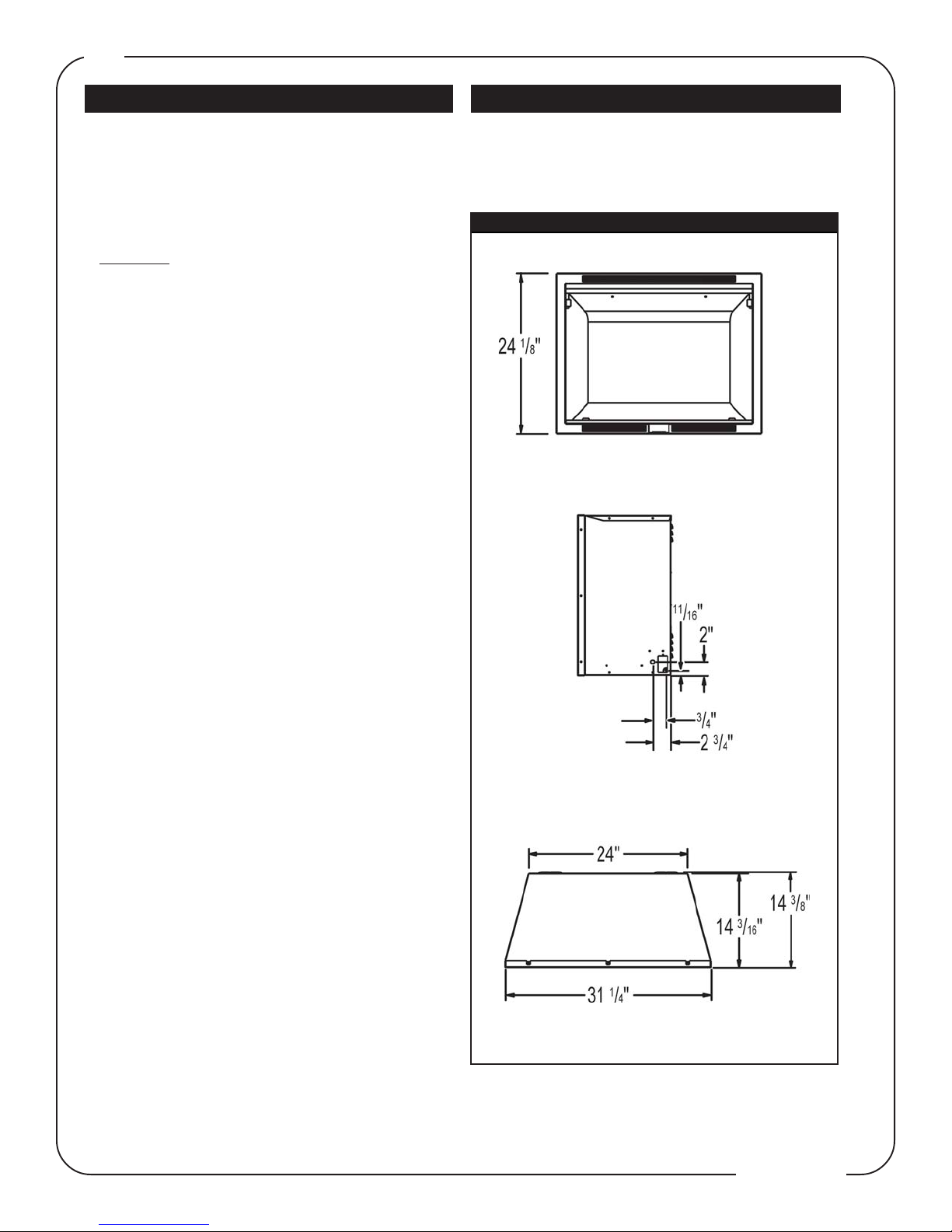
Your new fireplace may be installed into an existing masonry or zero clearance fireplace. It may also be installed
using a prefabricated cabinet available from your dealer or
may be built into a wall. For the best effect, install the fireplace out of direct sunlight.
EF31 DIMENSIONS
SAVE THESE INSTRUCTIONS.
19.
W415-0469 / C / 11.16.05
Page 5

OPERATION
There are two operation controls for the EF31.
1 - Controls the heater. 2 - Controls the flame effect.
Control Door
To access the controls,
slide the control door to
the right.
5
1. Heater
To set the heater at the maximum setting - roll the switch
up to the uppermost setting.
To turn the heater off - roll the switch down to the lower
most setting.
Flame effect
2.
The rocker switch is used to turn the flame effect on and
off. Depress the left side of the switch to turn the flame
effect on and the right side to turn off.
FLAME EFFECT
The flame generator has a random modulating control
which causes the flame effect to speed up and slow down
sporadically. This action creates the realistic flame appearance and can not be modified.
MAINTENANCE
Bulb Replacement : If the flame appears darker on one
side of the fireplace, check the light bulbs to ensure that
one has not burned out.
Bulb must be replaced with a MAX 75 watt Quartz 78mm
light bulb. See Light Replacement section.
FINISHING
MANTEL
The minimum distance from the top of the unit that the
mantel can be installed is 0", at any depth.
When using paint or lacquer to finish the
mantel, such paint or lacquer must be heat
resistant to prevent discolouration.
CLEARANCE TO COMBUSTIBLES
Sides......................... 0 inches
Sides................. 0 mm / 0 inches
Back..........................0 inches
Sides................. 0 mm / 0 inches
Floor..........................0 inches
Floor................. 0 mm / 0 inches
Top............................0 inches
Top 0 mm / 0 inches
FRAMING AND FINISHING
Nailing
Tab
Installation
Sheet
Metal
Screw
1. Choose fireplace location.
2. Place fireplace in position.
3. Frame in fireplace with header across the top. It is im-
portant to allow for the finished facing materials when setting the depth of the unit.
4. Remove the two screws from the sides of the fireplace
and attach the nailing tabs with the screws.
5. To determine the final location of the nailing tab, you
must first determine the thickness of your finishing material (i.e. sheetrock/drywall) This will determine the dimension from the front edge to the nailing tab. Secure with a
sheet metal screw supplied.
6. Attach the nailing tabs to the frame.
W415-0469 / C / 11.16.05
Page 6

6
EF31
Corner Installation
Top View
HEARTH
A hearth is NOT necessary but is recommended for aesthetic purposes.
COLD CLIMATE INSTALLATION
WARNING: It is MANDATORY to have an insulated wall behind the fireplace, when the fireplace is being installed
on an outside wall or chase.
GLASS REMOVAL
Front View
Note: In order to avoid the possibility of exposed insulation
or vapour barrier coming in contact with the fireplace
body, it is recommended that the walls of the fireplace enclosure be “finished” (ie: drywall/sheetrock), as you would
finish any other outside wall of a home. This will ensure that
clearance to combustibles is maintained within the cavity.
Remove the two screws holding the glass retainer and
pull the glass and retainer forward until the glass is past
the fireplace bottom. Lower and remove.
Place the glass and retainer in a safe spot.
LOG INSTALLATION
1. Position logs #1 and #2 as shown.
The diffuser base has been moulded to cradle the logs.
Vertical Groove
Be sure not to block the vertical groove running down the
centre of the dif fuser.
W415-0469 / C / 11.16.05
Page 7

OPTIONAL SCREEN INSTALLATION
1. Bunch the curtain mesh in the middle of the rod.
2. Insert one end of the rod through the hole indicated in the side
of the firebox frame.
3. The rod will need to be bowed in the middle in order to insert the
other end of the rod into the opposite hole.
4. Tuck the bottom of the curtain mesh behind the front lip of the
retainer.
ELECTRICAL CONNECTION
This fireplace requires a 15 amp, 120 volt and 60 hz
circuit. The fireplace should be on its own circuit. If
there are other appliances on the same circuit, this may
cause the circuit breaker or fuse to blow when the fireplace heater is in operation.
The unit comes with a 6' electrical cord, exiting the bottom right side. Plan your installation to avoid the use of
an extension cord. If you require an extension cord, it
must be at least 16 awg wire and be rated for 2025
watts.
Electrical outlet wires must comply with local building
codes to reduce the risk of fire, electrical shock and
injury.
Do NOT use the fireplace if any part has been under
water.
Call a qualified service technician IMMEDIATELY to have
the fireplace inspected for damage to the electrical circuit.
7
HARD WIRING CONNECTION
If it is necessary to hard wire this fireplace, a qualified
electrician may remove the cord connection, and wire
this unit directly to the house hold wiring.
Permanently framing the fireplace with an enclosure, requires the fireplace to be hardwired.
This fireplace must be electrically connected and grounded
in accordance with local codes, if hard wired. In the absence of local codes, use the current CSA C22.1 CANADIAN
ELECTRICAL CODE in Canada or the ANSI/NFPA 70-1996
NATIONAL ELECTRICAL CODE in the United States.
ELECTRICAL DIAGRAM LEGEND
1. Power (Rocker Switch) W660-0023
2. Thermostat Switch W660-0040
3. Fan / Heater Assembly W062-0019
4. Main Circuit Board W707-0003
5. DC Motor (flame effect) W435-0006
6. Main Power Cord W750-0143
7. Strain Relief W105-0002
8. Flame Effect Light W750-0126
(two light sockets-75quartz watts max)
9. Nylon Cable Tie
Electric Diagram
W415-0469 / C / 11.16.05
Page 8

8
HARD WIRING THE EF31
1. Remove the securing screw from the electrical cover
plate, located on the right hand side of the fireplace.
2. Feed the supply wires through the 7/8" knock out and
attach the ground wire to the ground screw on the
coverplate.
3. Pull the black and white wires out that have the marrets
on them.
4. Remove the marrets and secure the black wire (hot) to
the black (hot) lead of the power supply.
5. Connect the white wire from the unit to the white (common) wire from the power supply.
6. Replace and resecure the coverplate.
CLOSED END
SPLICE FOR
TO POWER
SUPPLY
WALL MOUNT
THERMOSTAT
CONNECTION
CONNECTING A
WALL THERMOSTAT
Thermostat must be rated for 120 vac
minimum 15 amps.
This function only operates the heater.
The thermostat knob on the unit must be turned to the
full position for the wall thermostat to work.
1. Remove the electrical box cover plate from the right side
of the fireplace.
2. Feed the thermostate wires through the 7/8" knock out
and attach the ground wire to the ground screw on the
coverplate.
3 a) Pull out the closed end splices from the electrical box
and cut the closed end splice off.
b) connect two wires to the newly exposed wires and run to
the thermostat location.
c) connect to the thermostat.
4. Replace and resecure the coverplate.
Closed End Splice
W415-0469 / C / 11.16.05
Page 9

WALL SWITCH MAIN POWER
WIRING
Use a single pole on/off switch rated for maximum
15 amps.
1. Remove the electrical box cover plate.
2. Feed the supply wires through the 7/8" knock out and
attach the ground wire to the ground screw on the
coverplate.
3. Connect one black wire to the black wire coming from
the electrical box, connect the other end to the wall switch.
4. Run a wire from the wall switch to the power supply.
5. Connect the white wire (common) from the power sup-
ply to the white (common) wire coming from the electrical
box on the fireplace.
9
WALL
SWITCH
POWER
SUPPLY
W415-0469 / C / 11.16.05
Page 10

10
LIGHT REPLACEMENT / RATING PLATE LOCATION
There are two methods to replace the light:
In either method, the electrical circuit breaker must be shut
off until the replacement procedure has been completed at
which time it can be turned back on.
Rating Plate these proceedure must be followed.
The Rating Plate is located on the inside of the panel.
To access the
2. Remove the five screws holding the defuser screen. Pull the
top two corners in towards the center and remove from the unit.
Light Bulb Replacement Method 1:
1. If the unit is not secured to the floor, turn the unit around to view
the access panel.
2. Remove the three screws securing the access panel. The
Rating Plate is located on the inside of the panel.
3. Remove the light bulb by holding one of the wires and moving
the light bulb to the opposite side of the wire that you are holding.
4. Replace using the new light bulb by following the removal
instructions in reverse.
5. Replace the access panel and put the fireplace back into position.
Light Bulb Replacement Method 2:
1. Remove the two screws holding the glass retainer and pull
forward to remove the glass. Place the glass and retainer in a
safe spot.
3. Remove the two screws that hold the flame divider in place and
remove.
4. Remove the light bulbs by holding one wire from one side of the
socket and slide the light bulb to the opposite side of the wire that
you are holding.
5. Repeat steps 4 through 1 to re-assemble the unit.
The Rating Plate is behind the lightbulbs.
W415-0469 / C / 11.16.05
Page 11

REPLACEMENTS
Contact your dealer for questions concerning prices and
availability of replacement parts. Normally all parts can be
ordered through your Napoleon dealer or distributor.
When ordering replacement parts always give the following information:
FOR WARRANTY REPLACEMENT PA RT S , A PHOTOCOPY OF
ORIGINAL INVOICE WILL BE REQUIRED TO HONOUR THE
THE
.
CLAIM
REPLACEMENT PARTS EF31 ACCESSORIES
# PART NO. DESCRIPTION
1 W497-0002 PLASTIC DIFFUSER
2 W062-0019 FAN / HEATER ASSEMBLY
3 W380-0016 THERMOSTAT KNOB
4 W387-0005 75 WATT QUARTZ LIGHT BULB
5 W435-0006 FLAME EFFECT MOTOR
6 W660-0040 THERMOSTAT SWITCH
7 W660-0023 MAIN POWER SWITCH
8 W010-1266 FLAME EFFECT ASSEMBLY
9 GL-648 LOG SET
10 W135-0227 LOG #1 - RIGHT LOG
11 W135-0228 LOG #2 - LEFT LOG
12 W200-0162 SCREEN COVER
13 W215-0077 FLAME EFFECT
14 W300-0078 GLASS
11
1. MODEL & SERIAL NUMBER OF FIREPLACE
2. INSTALLATION DATE OF FIREPLACE
3. PART NUMBER
4. DESCRIPTION OF PART
5. FINISH
* IDENTIFIES ITEMS WHICH ARE NO T ILLUSTRATED. FOR
FURTHER
Use only accessories designed for and listed with the
EF31 model.
# PART NO. DESCRIPTION
15 E31S SCREEN KIT
INFORMATION, CONTACT YOUR NAPOLEON
DEALER
.
W415-0469 / C / 11.16.05
Page 12

12
TROUBLE SHOOTING GUIDE
SYMPTOM PROBLEM TEST SOLUTION
No Flame Light but - Light bulbs have burned out. - Remove access panel and change
everything else is light bulbs.
working properly.
Flame light, but no - Flame generator motor has burned out. - Consult your local dealer.
movement in the flame - Flame generator has come loose. - Remove the access panel and check to make
sure the flame generator is in the flame
generator bracket, and is secured to the
motor with the rubber tube.
Heater works but - Fan on heater is not working. - Consult your local dealer.
there is no air flow.
Fan works but there is - Heater is not working. - Consult your local dealer.
no heat.
Fireplace will not - Breaker or fuse has blown. - Check main power switch is turned on.
turn on. - Fireplace cord is unplugged. - Consult your local dealer.
- Check fuse or breaker in house hold electric
panel.
- Plug cord back into receptacle.
Heater does not turn off. - Thermostat is set to high. - Turn thermostat control down.
- Thermostat may be faulty. - Consult your local dealer.
Excessive noise coming - Dirt build up on fan bearing. - Vacuum the top control compartment.
from the top of the unit. - Defective blower. - Consult your local dealer.
Odour - Dust has settled on the - Run heater until odour ceases
heater element. (approx. 1/2 hr)
- Consult your local dealer.
Heater cycling on - Air intlets blocked. - Check to make sure there is nothing blocking
and off the air inlets on the bottom of the unit.
- Should not be on high pile carpet that can
block air inlets.
W415-0469 / C / 11.16.05
Page 13

NOTES
13
W415-0469 / C / 11.16.05
Page 14

14
NOTES
W415-0469 / C / 11.16.05
 Loading...