

Page 1

SERIAL #______________________
BUILT-IN UNIT INSTRUCTION GUIDE
Please use this manual in conjuction with your main manual to properly assemble your built-in grill. Refer to the
main manual for operating, cleaning, and maintenance instructions. This grill is designed for non-combustible
enclosures only , and must be installed and serviced by a qualified installer to local codes.
BUILT IN PROPANE GAS HOOK-UP: The piping up to the gas grill is the responsibility of the installer and piping should be located as
shown in the built-in instructions. Do not use hose to connect the unit. It must be connected with either rigid pipe, copper tube or an
approved flexible metal connector. The installation must comply with CAN B149.1 Natural Gas and Propane installation code in
Canada, or to the National Fuel Gas code, ANSI Z223.1 in the United States. The minimum recommended piping size is NPS 1/2"
for rigid pipe, and 1/2" OD for copper tubing (based on a 20 ft run). Longer runs may require larger sizes to conform with CAN
B149.1. Propane Gas Installation Code in Canada or to the National Fuel Gas Code, ANSI Z223.1 in the United States. The gas
supply must be connected to the 3/8” flare elbow fitting located under the right hand side of the control panel. If installing a side
burner, a separate line must be branched off to the side burner unit and enter the side burner opening at the specified location. If the
enclosure is to house a propane cylinder, the tank portion of the enclosure must be ventilated according to local codes, and must not
have communication with the cavity used to enclose the gas grill. The tank can not be stored below the gas grill.
BUILT IN NATURAL GAS HOOK-UP: The piping up to the gas grill is the responsibility of the installer and piping should be located as
shown in the built-in instructions. Do not use hose to connect the unit. It must be connected with either rigid pipe, copper tube or an
approved flexible metal connector. The installation must comply with CAN B149.1 Natural Gas and Propane Installation Code in
Canada, or to the National Fuel Gas Code, ANSI Z223.1 in the United States. The minimum recommended piping size is NPS 1/2"
for rigid pipe, and 5/8" OD for copper tubing (based on a 20 ft run). Longer runs may require larger sizes to conform with CAN
B149.1. Natural Gas Installation Code in Canada or to the National Fuel Gas Code, ANSI Z223.1 in the United States.
Built in units are supplied with a drip pan which holds only a minimal amount of grease. T oprevent grease fires, the panmust
be cleaned after each use.
N415-0107/APR28/06
Page 2
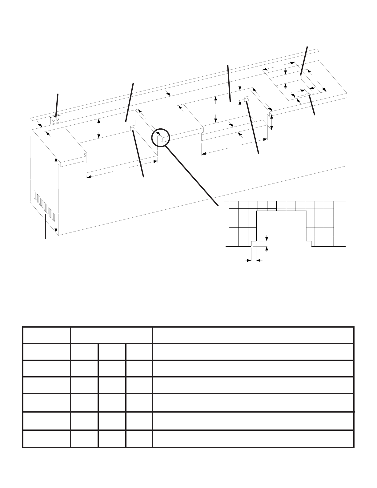
BUILT-IN UNITOPENING DIMENSIONS
OUTDOOR GFIOUTLET
RECOMMENDED -LOCATE
ON LEFT SIDE OF GRILL
FOR ROTISSERIE USE.
BIPT450 / BIPT600 / BIPT750
BUILT-INGRILLHEADS
3”MIN.
BIU405 BUILT-IN
GRILL HEADS
6”
H
BUILT-IN
SIDEBURNER
W
H
D
1¾”
D
1¾”
2”
34”
RECOMMENDED
MINIMUM10SQINOF
VENTILATIONREQUIRED
ON EACH END OF CABINET
D
H
W
GASINLET
OPENING
4”
W
GASINLET
OPENING
WIDE 1 ¼”
OVERHANG NOTCHREQUIREDIF
USING SUPPLIEDTRIMKIT.
7”
DEPTH OF
COUNTERTOP
OVERHANG
GASINLET
OPENING
MODEL OPENINGDIMENSIONS
WDH
BIPT450 29 ½”20e”8f”
BIPT600 37 ¾”20e”8f”
BIPT750 49 ¾”20e”9e”
BIU405 27 ½”16¾” 12”
SIDEBURNER 13 ½”17½”4”
NOTES
Access must be provided for drip tray removal and cleaning.
Opening of at least 5 sq in must be provided for combustion air for side burner.
Page 3
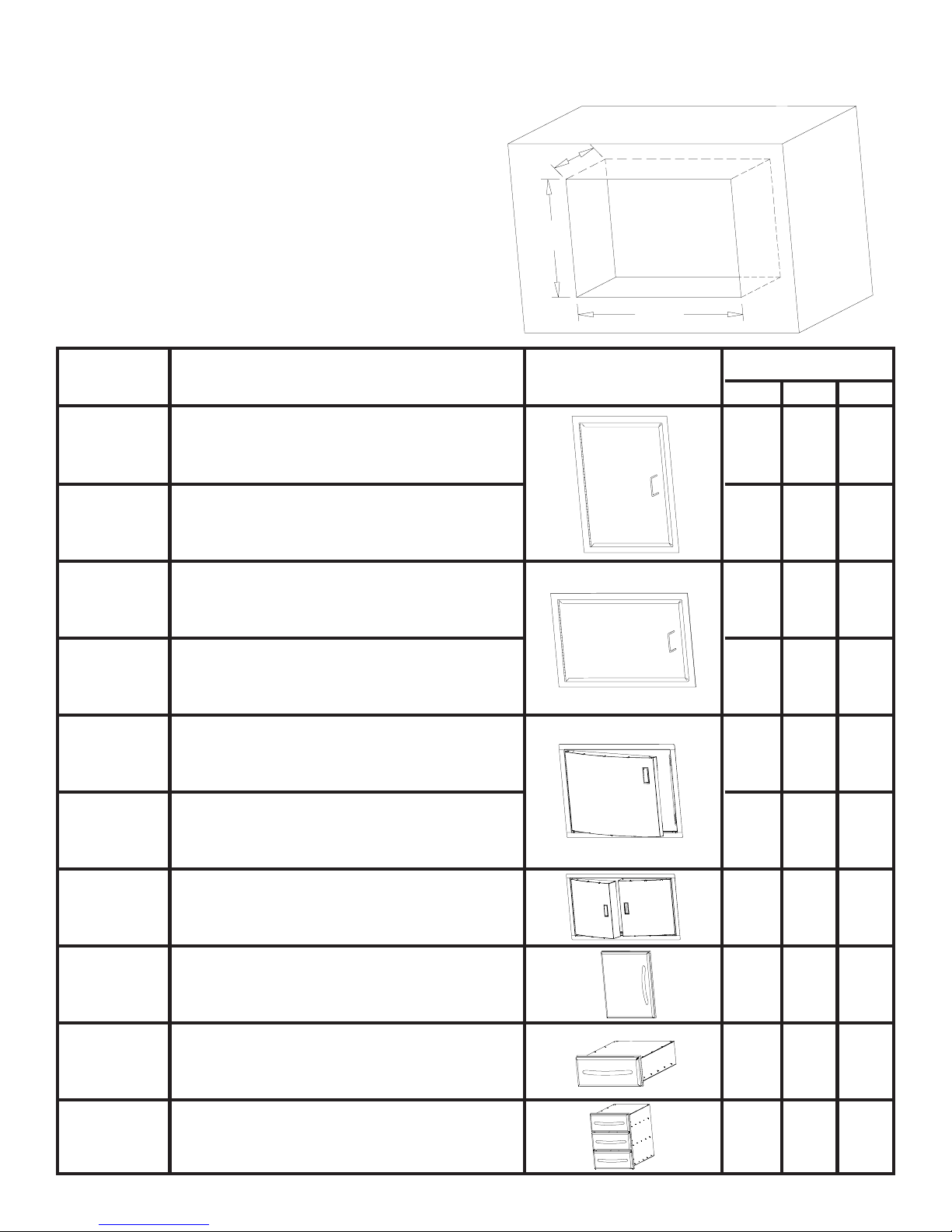
BUILT-INACCESSORYOPENING DIMENSIONS
NOTE:ACCESSORYFRAMES OVERLAP
OPENINGBY 1½” ONALL4SIDES
D
H
W
Part #
N370-0069 Flat vertical painted door
N370-0071
N370-0070
N370-0072
N370-0356SS Curved stainless steel door - 308 size
Flat vertical stainless steel door
Flat horizontal painted door
Flat horizontal stainless steel door
Description
Picture
OPENINGDIMENSION
WH
13¼”
18¼”
D
13¼” 18¼”
18¼” 13 ¼”
18¼” 13 ¼”
22½” 19 ¾”
N370-0357SS
N370-0358SS
N370-0361 PF style stainless steel door
N370-0359 PF style stainless steel single drawer
N370-0360 PF style stainless steel triple drawer
Curved stainless steel door - 450 size
Curved stainless steel double door - 600/750 size
27” 19 ¾”
35¼” 19”
17”
23¼”
17¼” 6 ¾”
17¼” 22 ¾”
23”
23”
Page 4

1. BIPT450 BUILT-IN INSTRUCTIONS
N080-0142
N570-0026
N715-0062
N080-0142
N715-0060
N715-0059
N710-0027
N715-0061
This grill is designed for masonry, non-combustible enclosures only, and must be installed and serviced by a qualified installer to
local codes.
1. Attach side mounting brackets and side trim pieces to each side of the grill using #14 x 1/2" screws (n570-0026).
2. Mount the lower front trim to the bottom front edge of the opening (fasteners not included).
3. Lay the rear trim piece across the back of the opening. To keep it in place, a dab of silicone may be applied to each wing of the
rear trim.
4. Lower the unit in place, and connect the gas supply line to the fitting at the end of the manifold.
5. The unit must be secured in place (fasteners not included). This can be accomplished by mounting the left and right trim pieces
to the sides of the opening, or by another means.
6.The entire installation must be leak tested before operating the unit.
Page 5

2. BIPT600 BUILT-IN INSTRUCTIONS
N080-0066
N715-0059
N380-0009
N051-0001
N715-0072
N080-0142
N710-0044
N570-0026
N715-0060
This grill is designed for masonry, non-combustible enclosures only, and must be installed and serviced by a qualified installer to
local codes.
1. Attach side mounting brackets and side trim pieces to each side of the grill using 1/4-20 x 1/2" screws (n570-0026).
2. Mount the lower front trim to the bottom front edge of the opening (fasteners not included).
3. Lay the rear trim piece across the back of the opening. To keep it in place, a dab of silicone may be applied to each wing of the
rear trim.
4. Lower the unit in place, and connect the gas supply line to the fitting at the end of the manifold.
5. The unit must be secured in place (fasteners not included). This can be accomplished by mounting the left and right trim pieces
to the sides of the opening to the sides of the cabinet.
6.The entire installation must be leak tested before operating the unit.
Page 6

2. BIPT750 BUILT-IN INSTRUCTIONS
N715-0076
N715-0059
N380-0009
N051-0001
N715-0077
N080-0142
N710-0044
N570-0026
N715-0060
This grill is designed for masonry, non-combustible enclosures only, and must be installed and serviced by a qualified installer to
local codes.
1. Attach side mounting brackets and side trim pieces to each side of the grill using 1/4-20 x 1/2" screws (n570-0026).
2. Mount the lower front trim to the bottom front edge of the opening (fasteners not included).
3. Lay the rear trim piece across the back of the opening. To keep it in place, a dab of silicone may be applied to each wing of the
rear trim.
4. Lower the unit in place, and connect the gas supply line to the fitting at the end of the manifold.
5. The unit must be secured in place (fasteners not included). This can be accomplished by mounting the left and right trim pieces
to the sides of the opening to the sides of the cabinet.
6.The entire installation must be leak tested before operating the unit.
Page 7

3. BIU405 BUILT-IN INSTRUCTIONS
N080-0152
N570-0026
N570-0026
N080-0152
N715-0063
N570-0026
23 e c-c
N080-0155
N080-0155
This grill is designed for masonry, non-combustible enclosures only, and must be installed and serviced by a qualified installer to
local codes. Access must be provided in the enclosure for drip tray removal and cleaning.
1. Attach the side mounting brackets and the rear trim to the unit using #14 x 1/2” screws (n570-0026). The wings on the rear trim
should be under the side mounting brackets.
2. Attach the supplied brackets flush with the front of the opening as per the dimensions in the above drawing (fasteners not included).
3. Lower the unit in place ensuring the brackets installed in the previous step engage between the control panel and the base
bracket. Connect the supply line to the fitting at the end of the manifold.
4. The entire installation must be leak tested before operating the unit.
Page 8

4. BUILT-IN SIDE BURNER INSTRUCTIONS
N280-0003P (BLACK)
N280-0004 (STN STL)
1. Fit the side burner frame into the opening. The frame should be attached to the opening to prevent any future movement (fasteners not included).
2. Ensure that there is at least 5 sq in of opening in the bottom of the cut out, for combustion air.
3. Set the side burner into the frame.
4. Connect the gas supply to the side burner valve. Leak test the entire installation before operating the unit.
Page 9

5. BUILT-IN ACCESSORY DRAWER INSTRUCTIONS
1.Unpackthedrawerframeassembly.
2.Remove the drawers from the enclosure by fully extending them and then liftinguptoremovethemfrom the slides.
3. Shim the opening to ensure that the enclosure fits snuggly into the opening. Ensure that the side shims are located at
the same height as the enclosure mounting holes. The bottom of the opening mayneed to be shimmed as well to ensure
that the front of the enclosure is plumb.
4. Once the enclosure islevel and square, fasten into place. (Fasteners not included).
5. Re-install the drawers by tipping the back of the drawer down into the slide. Once the wheels are inserted into the slide,
lower the front of the drawer until it is level, then push in. Note: if the enclosure is installed with shims that are too thick, the
wheel will not engage into the slide. The shim thickness will need to be reduced.
6.Removetheprotectivecoatingfromallremainingsurfaces.
6. BUILT-IN ACCESSORY DOOR INSTRUCTIONS
1. Unpack the door and frame.
a. For the curved stainless steel doors, removethedoor(s) from the frame by lifting the doorwhileholding on to the pivot
rod. This will allow the pivot rodto come out of the hole on the bottom of the frame. Once the pivot is removedfrom the
bottomhole, the entire door can be dropped and removed from theframe.
b. For the PF style stainless steel door, the door needs to be removed by loosening the center philipsscrew on the hinge
furthest away from the door. This will allow the hingeto separate.
2. Center the frame in the opening. Mark the location of the pivot holes,top and bottom. Remember on the PT600 double
doors, there will be a pivot rod on both ends. The PF style doors do not have pivotrods. Once all pivot holes are marked,
remove the frame and using a3/8” drill bit, drill out the clearanceholes for the pivot rod. Theseclearance holes should be
at least 1/2” deep. After the holes are complete, you may once again center the frame in the opening. Starting with the
hinged side, shim between the frame and side wall of the opening. Ensure the shims are close to the hinge on the PF style
doors. When the frame side wall is plumb, fasten it to the cabinet with screws (not provided). Attach the other side of the
frame in the same fashion, ensuring the frameissquare.
3. Other than on the curved stainless steel doubledoor kit, fasteners arenot required on the top and bottom of theframe.
The curved stainless steel double door frame must be fastened in the centerboth at the top and bottom.
4. Once the frame has been securedand checked for squareness, the door canbe re-installed.
5.Remove the protective coating from all remaining surfaces.
 Loading...