

Napoleon Bipt600rb Owner's Manual

SERIAL #______________________
BUIL T -IN UNIT INSTRUCTION GUIDE
Please use this manual in conjunction with your main manual to properly assemble your built-in grill. Refer to
the main manual for operating, cleaning, and maintenance instructions. This grill is designed for NON-COM-
BUSTIBLE enclosures only, and must be installed and serviced by a qualified installer to local codes.
BUILT IN PROPANE GAS HOOK-UP: The piping up to the gas grill is the responsibility of the installer and piping should be located as
shown in the built-in instructions. A flexible metal connector is included to simplify the installation of the unit. Connect this connector
to the 3/8” flare fitting on the end of the manifold. Connect the other end of the connector to the gas piping. Ensure that the
connector does not pass through a wall, floor, ceiling or partition, and is protected from damage. Do not use hose to connect the
unit. It must be connected with either rigid pipe, copper tube or an approved flexible metal connector. The installation must comply
with CAN B149.1 Natural Gas and Propane installation code in Canada, or to the National Fuel Gas code, ANSI Z223.1 in the United
States. The minimum recommended piping size is NPS 1/2" for rigid pipe, and 1/2" OD for copper tubing (based on a 20 ft run).
Longer runs may require larger sizes to conform with local codes or to conform with CAN B149.1. Propane Gas Installation Code in
Canada or to the National Fuel Gas Code, ANSI Z223.1 in the United States. The gas supply must be connected to the 3/8” flare
elbow fitting located under the right hand side of the control panel. If installing a side burner, a separate line must be branched off to
the side burner unit and enter the side burner opening at the specified location. If the enclosure is to house a propane cylinder, the
tank portion of the enclosure must be ventilated according to local codes, and must not have communication with the cavity used to
enclose the gas grill. A propane tank can not be stored below the gas grill.
BUILT IN NATURAL GAS HOOK-UP: The piping up to the gas grill is the responsibility of the installer and piping should be located as
shown in the built-in instructions. A flexible metal connector is included to simplify the installation of the unit. Connect this connector
to the 3/8” flare fitting on the end of the manifold. Connect the other end of the connector to the gas piping. Ensure that the connector
does not pass through a wall, floor, ceiling or partition, and is protected from damage. Do not use hose to connect the unit. It must
be connected with either rigid pipe, copper tube or an approved flexible metal connector. The installation must comply with CAN
B149.1 Natural Gas and Propane Installation Code in Canada, or to the National Fuel Gas Code, ANSI Z223.1 in the United States.
The minimum recommended piping size is NPS 1/2" for rigid pipe, and 5/8" OD for copper tubing (based on a 20 ft run). Longer
runs may require larger sizes to conform with local codes or to conform with CAN B149.1. Natural Gas Installation Code in Canada
or to the National Fuel Gas Code, ANSI Z223.1 in the United States.
Built in units are supplied with a drip pan which holds only a minimal amount of grease. To prevent grease fires, the pan must
be cleaned after each use.
DANGER: READ ALL INSTRUCTIONS CAREFULLY BEFORE OPERA TING GRILL. FAILURE T O FOLLOW
THESE INSTRUCTIONS EXACTL Y COULD RESUL T IN A FIRE CAUSING SERIOUS INJUR Y OR DEA TH.
THE ENTIRE INST ALLATION MUST BE LEAK TESTED BEFORE OPERA TING THE GRILL.
N415-0175 / MAR 04/08
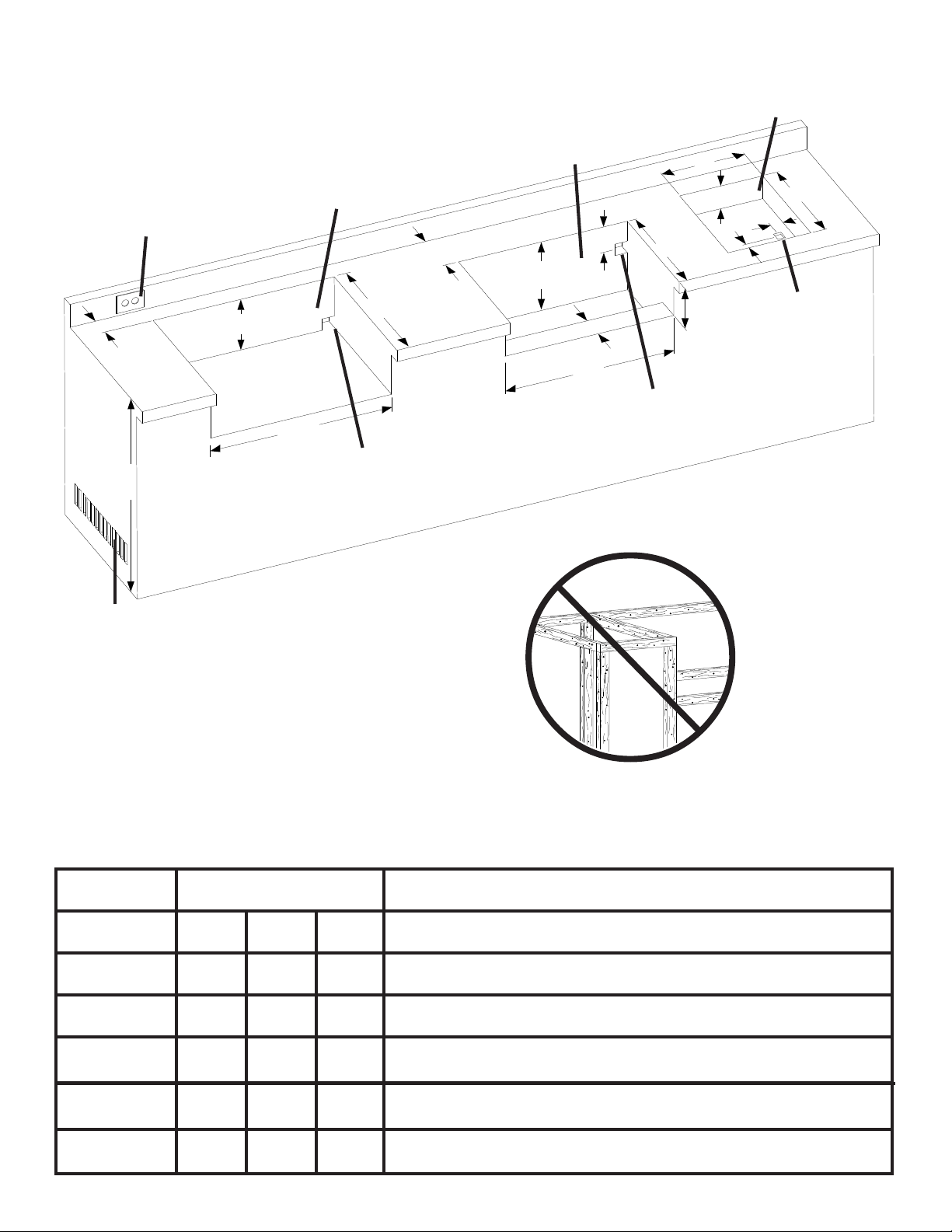
BUIL T -IN UNIT OPENING DIMENSIONS
OUTDOOR GFI ELECTRICAL
OUTLET RECOMMENDED -
LOCA TE ON LEFT SIDE OF
GRILL FOR ROTISSERIE
USE.
BIPT450 / BIPT600 / BIPT750
BUILT-IN GRILL HEADS
3” MIN.
BIU405 BUILT-IN
GRILL HEADS
6”
H
BUILT-IN
SIDEBURNER
W
H
D
1¾”
D
1
¾”
2”
34”
RECOMMENDED
MINIMUM 10 SQ IN OF
VENTILATION REQUIRED
ON EACH END OF CABINET
D
H
W
GAS INLET
OPENING
4”
W
GAS INLET
OPENING
7”
GAS INLET
OPENING
NON-COMBUSTIBLE MATERIAL
MODEL OPENING DIMENSIONS
W D H
BIPT450 29 1/2” 20 5/8” 8 7/8”
BIPT600 37 3/4” 20 5/8” 8 7/8”
BIPT750 49 3/4” 20 5/8” 9 5/8”
BIU405 271/2” 16 3/4” 12”
SIDE BURNER 13 1/2” 17 1/2” 4”
CABINET FRAME AND CABINET MUST BE
MADE FROM NON-COMBUSTIBLE MATERIAL
NOTES
Access must be provided for drip tray removal and cleaning.
Opening of at least 5 sq in must be provided for combustion air for side burner.
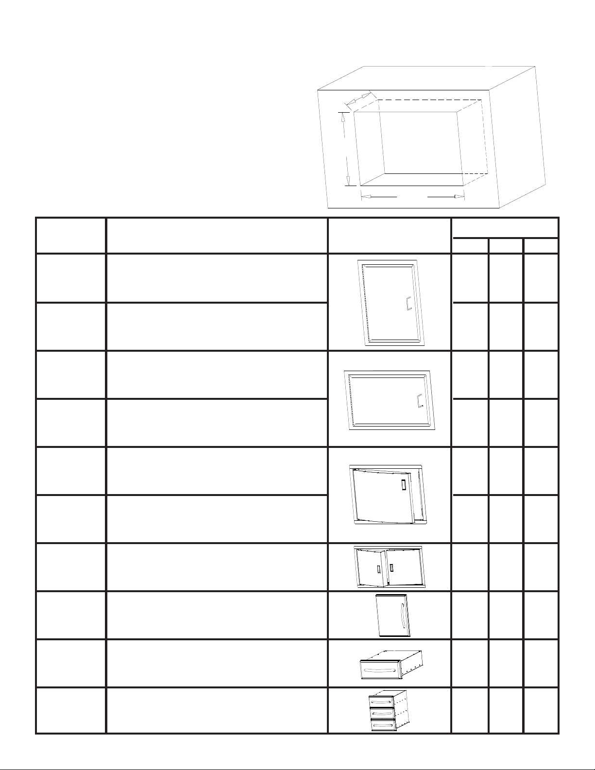
BUIL T -IN ACCESSORY OPENING DIMENSIONS
NOTE: ACCESSORY FRAMES OVERLAP
OPENING BY 1 ½” ON ALL 4 SIDES
D
H
W
Part #
N370-0069 Flat vertical painted door
N370-0071
N370-0070
N370-0072
N370-0356SS Curved stainless steel door - 308 size
Flat vertical stainless steel door
Flat horizontal painted door
Flat horizontal stainless steel door
Description
Picture
OPENING DIMENSION
WH
13 ¼”
18 ¼”
D
13 ¼” 18 ¼”
18 ¼” 13 ¼”
18 ¼” 13 ¼”
22 ½” 19 ¾”
N370-0357SS
N370-0358SS
N370-0361 PF style stainless steel door
N370-0359 PF style stainless steel single drawer
N370-0360 PF style stainless steel triple drawer
Curved stainless steel door - 450 size
Curved stainless steel double door - 600/750 size
27” 19 ¾”
35 ¼” 19”
17”
23 ¼”
17 ¼” 6 ¾”
17 ¼” 22 ¾”
23”
23”
 Loading...