

Napoleon Altitude X, Altitude AX36NTE, Altitude AX42NTE, Altitude AX36PTE, Altitude AX42PTE Owner's Manual

ENGLISH
FRENCH
PG. 21
OWNER’S MANUAL
Altitude™ X Series
(AX42 illustrated)
For indoor use only
SAFETY INFORMATION
!
WARNING
FIRE OR EXPLOSION HAZARD
Failure to follow safety warnings exactly could result in serious injury, death, or property damage.
- Do not store or use gasoline or other fl ammable vapors and liquids in the vicinity of this or any other appliance.
- WHAT TO DO IF YOU SMELL GAS:
• Do not try to light any appliance.
• Do not touch any electrical switch; do not use any phone in your building.
• Immediately call your gas supplier from a neighbour’s phone. Follow the gas supplier’s instructions.
• If you cannot reach your gas supplier, call the fi re department.
- Installation and service must be performed by a qualifi ed installer, service agency, or the supplier.
Wolf Steel Ltd., 24 Napoleon Rd., Barrie, ON, L4M 0G8 Canada / 103 Miller Drive, Crittenden, Kentucky, USA, 41030
Phone 1 (866) 820-8686 • www.napoleon.com • hearth@napoleon.com
W415-1939 / A / 05.07.19

EN
safety information
WARNING
!
• This appliance is hot when operated and can cause
severe burns if contacted.
• Any changes to this appliance or its control can be
dangerous and are prohibited.
• Do not operate appliance before reading and
understanding operating instructions. Failure
to operate appliance according to operating
instructions could cause fi re or injury.
• Risk of fi re or asphyxiation do not operate appliance
with fi xed glass removed.
• Do not connect 110 volts to the control valve.
• Risk of burns. The appliance should be turned off
and cooled before servicing.
• Do not install damaged, incomplete or substitute
components.
• Risk of cuts and abrasions. Wear protective gloves
and safety glasses during installation. Sheet metal
edges may be sharp.
• Children and adults should be alerted to the
hazards of high surface temperature and should
stay away to avoid burns or clothing ignition.
• Young children should be carefully supervised
when they are in the same room as the appliance.
Toddlers, young children, and others may be
susceptible to accidental contact burns. A
physical barrier is recommended if there are at
risk individuals in the house. To restrict access to
an appliance or stove, install an adjustable safety
gate to keep toddlers, young children and other at
risk individuals out of the room and away from hot
surfaces.
• Clothing or other fl ammable material should not be
placed on or near the appliance.
• Due to high temperatures, the appliance should be
located out of traffi c and away from furniture and
draperies.
• Ensure you have incorporated adequate safety
measure to protect infants/toddlers from touching
hot surfaces.
• Even after the appliance is out, the glass and/or
screen will remain hot for an extended period of
time.
• Check with your local hearth specialty dealer
for safety screens and hearth guards to protect
children from hot surfaces. These screens and
guards must be fastened to the fl oor.
• Any safety screen, guard or barrier removed for
servicing the appliance, must be replaced prior to
operating the appliance.
• The appliance is a vented gas-fi red appliance. Do
not burn wood or other materials in the appliance.
• The appliance area must be kept clear and free
from combustible materials, gasoline and other
fl ammable vapors and liquids.
• Under no circumstances should this appliance be
modifi ed.
• This appliance must not be connected to a chimney
fl ue pipe serving a separate solid fuel burning
appliance.
• Do not use this appliance if any part has been
under water. Immediately call a qualifi ed service
technician to inspect the appliance and to replace
any part of the control system and any gas control
which has been under water.
• Do not operate the appliance with the glass door
removed, cracked or broken. Replacement of the
glass should be done by a licensed or qualifi ed
service person.
• Do not strike or slam shut the appliance glass door.
• When equipped with pressure relief doors, they
must be kept closed while the appliance is
operating to prevent exhaust fumes containing
carbon monoxide, from entering into the home.
Temperatures of the exhaust escaping through
these openings can also cause the surrounding
combustible materials to overheat and catch fi re.
• Only doors / optional fronts certifi ed with the unit
are to be installed on the appliance.
• Keep the packaging material out of reach of
children and dispose of the material in a safe
manner. As with all plastic bags, these are not toys
and should be kept away from children and infants.
• As with any combustion appliance, we recommend
having your appliance regularly inspected and
serviced as well as having a carbon monoxide
detector installed in the same area to defend you
and your family against carbon monoxide.
• Ensure clearances to combustibles are maintained
when building a mantel or shelves above the
appliance. Elevated temperatures on the wall or
in the air above the appliance can cause melting,
discolouration or damage to decorations, a T.V. or
other electronic components.
• A barrier designed to reduce the risk of burns from
the hot viewing glass is provided with this appliance
and shall be installed.
• If the barrier becomes damaged, the barrier shall
be replaced with the manufacturer’s barrier for this
appliance.
• Installation and repair should be done by a qualifi ed
service person. The appliance should be inspected
before use and at least annually by a professional
service person. More frequent cleaning may be
required due to excessive lint from carpeting,
bedding material, etc. It is imperative that control
compartments, burners and circulating air
passageways of the appliance be kept clean.
2
W415-1939 / A / 05.07.19
table of contents
1.0 getting to know your appliance 5
1.1 control access 6
1.2 rating plate information 6
2.0 operating your appliance 7
2.1 initializing the transmitter / battery holder for the fi rst time 7
2.2 using your appliance 7
3.0 remote control layout 8
3.1 general transmitter layout 8
3.2 temperature display 8
3.3 fl ame height 9
3.4 blower speed 9
3.5 night light dimmer control 9
3.6 in the event of a power failure 9
3.7 continuous pilot / intermittent pilot (CPI/IPI) selection 9
3.8 eFIRE Controller application 10
3.9 low battery 10
3.10 battery holder / backup installation 10
4.0 clearances around appliance 11
5.0 maintenance 13
5.1 care of glass 13
5.2 care of plated parts 14
5.3 safety barrier removal 14
5.4 fi rebox glass door removal 14
6.0 replacement parts 15
7.0 AX36 accessories 16
8.0 AX42 accessories 17
9.0 troubleshooting 18
10.0 warranty 19
EN
Before reading this manual, be sure you know which model of appliance that you have. This information will have
been fi lled out by the installer on the following page and on the rating plate that is permanently attached to the appliance (see “rating plate information” section).
This manual is for the:
• Altitude X Series (AX36 and AX42 models)
If required, more detailed technical information is included in the appliance installation manual.
The information throughout this manual is believed to be correct at the time of printing. Wolf Steel Ltd. reserves
the right to change or modify any information within this manual at any time without notice.
Visit the Napoleon website for the most current version of your appliance’s manual.
Changes, other than editorial, are denoted by a vertical line in the margin.
Batteries must be disposed of according to the local laws and regulations. Some batteries may be
recycled, and may be accepted for disposal at your local recycling center. Check with your
municipality for recycling instructions.
!
WARNING:
which are known to the State of California to cause cancer, and chemicals including carbon
monoxide, which are known to the State of California to cause birth defects or other reproductive harm. For more information, go to www.P65Warnings.ca.gov.
This product can expose you to chemicals including lead and lead compounds,
W415-1939 / A / 05.07.19
3
EN
welcome
congratulations!
Napoleon is proudly committed to your total home comfort. We are proud to say that our products continunously
surpass industry standards and our inspiration is you! More than anything, we want you to feel confi dent in
choosing Napoleon for your home. Our products are designed to provide that confi dence and ensure that every
Napoleon product is beyond compare.
Napoleon products are designed with superior components and materials assembled by trained craftsmen who
take great pride in their work.
A barrier designed to reduce the risk of burns from the hot viewing glass is provided with the appliance for your
safety. This barrier must be installed.
Your Napoleon appliance has been thoroughly inspected by a qualifi ed technician before packaging to ensure that
you, the customer, receives the quality product that you expect from Napoloen.
Dealer : Fill in your dealer information (or business card) and the appliance installation information
below.
Dealer Information
Name of Dealer:
Dealer Location:
Dealer Phone:
Dealer E-mail:
Customer:
Customer Address:
Date of Installation:
Location of the appliance:
Installer:
Dealer: Business card location
Serial Number:
Model:
4
W415-1939 / A / 05.07.19
Natural Gas: AX36NTE
AX42NTE
Propane: AX36PTE
AX42PTE
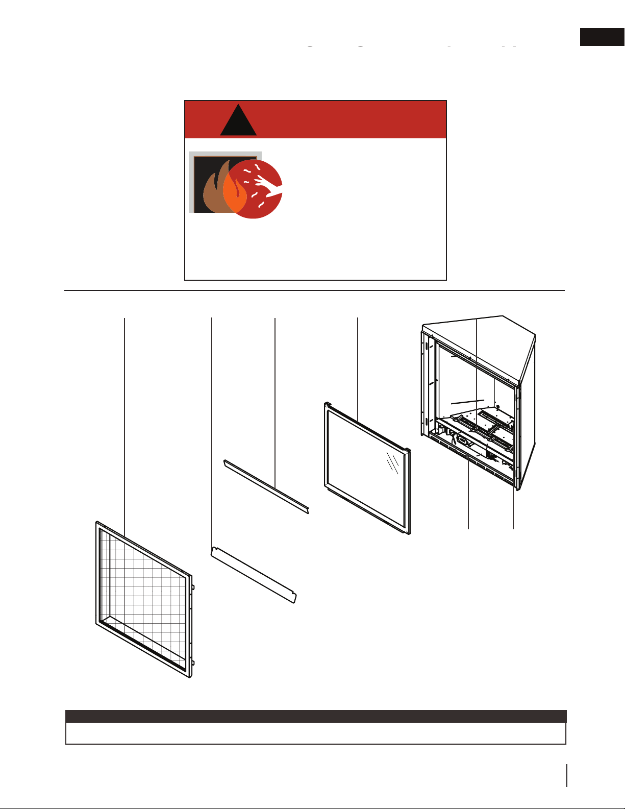
1.0 getting to know your appliance
The area above the appliance opening including the safety barrier, barrier frame and
the surface of the wall can get very hot during operation and should never be touched
until the appliance is off and completely cooled.
!
DANGER
A barrier designed to reduce the risk of burns from
the hot viewing glass is provided with this appliance
and shall be installed for the protection of children
and other at-risk individuals.
getting to know your appliance
HOT GLASS WILL CAUSE BURNS.
DO NOT TOUCH GLASS UNTIL
COOLED.
NEVER ALLOW CHILDREN TO
TOUCH GLASS.
EN
Safety barrier
Bottom trim
Top trim
Glass door
Burner
Valve / rating
plate / lighting
instructions /
battery back up
Pilot
note:
Some features and locations may vary depending on the model.
W415-1939 / A / 05.07.19
5
EN
24 CFR,
24 CFR, Part 3280,
Ali
Alimentation
A
éduiteAlimentation Réduite
)11” w.c. (P)
)13”* w.c
au Collecteur: u Collecteur:
Alimentation Max.:on Max.:
égagements minimaux des matériaux comégagements minimaux des matériaux co
VENTED DECORATIVE GAS VENTED DECORATIVE GAS
APPLIAAPPLIA
APPAREIL À GAZAPPAREIL À GA
getting to know your appliance
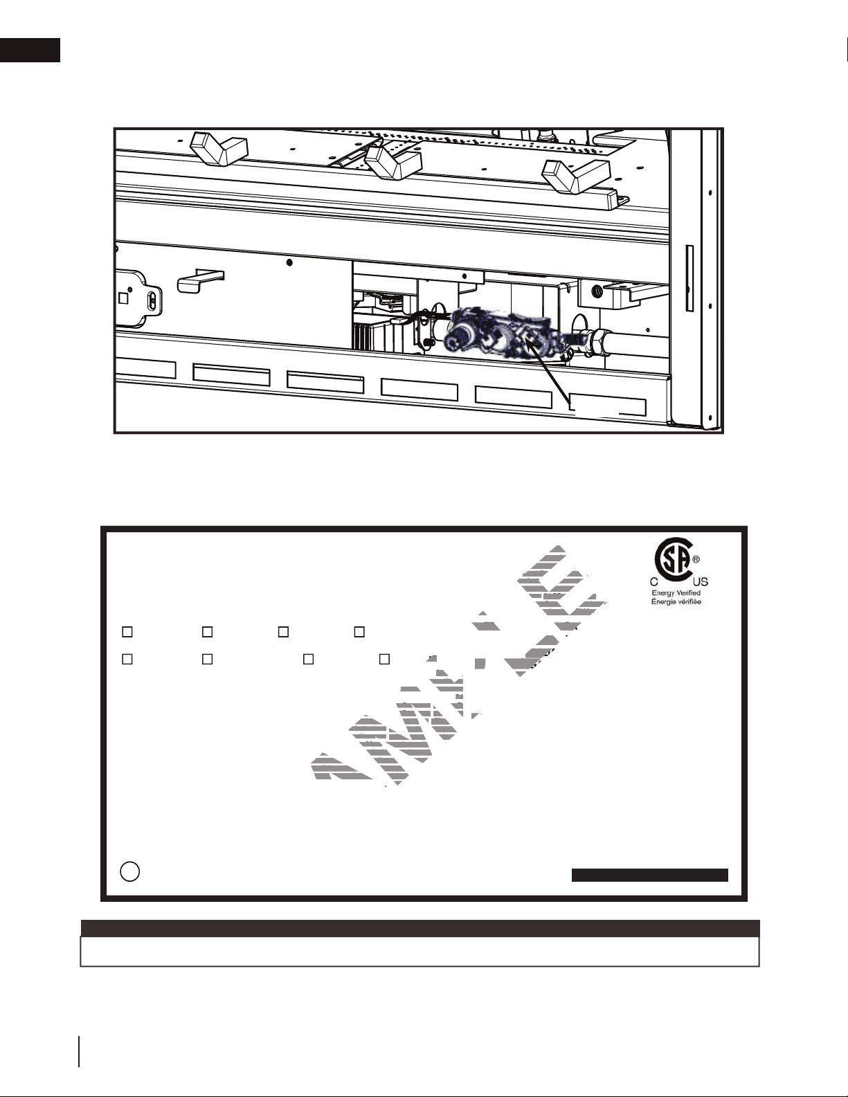
1.1 control access
Access to the control can be done by removing the safety barrier, glass door and door trims (see “maintenance”
section for instructions on how to remove these components).
VALVE
1.2 rating plate information
This illustration is for reference only. Refer to the rating plate on the appliance for accurate information.
Certified to Canadian and American National Standards: CSA 2.22-2016 / ANSI Z21.50-2016 for Vented Decorative Gas Appliances
Certifié selon les normes Nationales Canadiennes et Américaines: CSA 2.22-2016 / ANSI Z21.50-2016 pour les Appareils à gaz décoratif à évacuation
Direct vent, vented gas fireplaces. Approved for bedroom, bathroom and bed-sitting room installation. Suitable for mobile home installation, if installed in accordance with the current
standard CAN / CSA Z240MH Series gas equipped mobile homes in Canada, or, in the United States, the Manufactured Home Construction and Safety Standard, Title 24 CFR, Part
3280. When this US Standard is not applicable, use the Standard for Fire Safety Criteria for Manufactured Home Installations, Sites and Communities, ANSI / NFPA 501A. This appliance
must be installed in accordance with local codes, if any; if none, follow the current ANSI Z223.1 or CSA B149. For use with barrier W565-0320. Follow installation instructions.
Foyer à gaz ventilé. Homologué pour installation dans une chambre à coucher, une salle de bain et un studio. Approprié pour installation dans une maison mobile si son installation
conforme aux exigences de la norme CAN / CSA Z240MH Séries de maisons mobile équipées au gaz en vigueur au Canada, ou, aux États-Unis selon la norme 24 CFR, Part 3280,
Manufactured Home Construction and Safety Standard. Dans le cas ou cette norme d’États-Unis n’est pas pertinentes, utiliser la norme NFPA 501A, Fire Safety Criteria for Manufactured
Home Installations, Sites and Communities. Installer l’appareil selon les codes ou règlements locaux ou, en l’absence de tels règlements, selon les codes d’installation ANSI Z223.1 ou
CSA B149 en vigueur. Utiliser uniquement avec l’écran W565-0320. Suivre les instructions d’installation.
9700539 (WSL) 4001658 (NAC) 4001657 (NGZ) 4001659 (WUSA)
MODEL / MODÈLE
AX36NTE CAX36NTE CAX36PTE AX36PTE
Altitude
Input
Reduced Input
P4
Manifold Pressure: 3.5” w.c. (NG)
Minimum Supply Pressure: 4.5” w.c. (NG)
Maximum Supply Pressure: 7”* w.c. (NG)
Pression au Collecteur: 3,5” d’une colonne d’eau (GN)
Pression d’Alimentation Min.: 4,5” d’une colonne d’eau (GN)
Pression d’Alimentation Max.: 7” ** d’une colonne d’eau (GN)
** Maximum inlet pressure not to exceed 13”.
Minimum clearance to combustible materials:
Top, sides & back: per standoff spacers for framing and finishing
materials. For non-combustible framing and finishing materials,
see installation manual.
Top 0”
Floor 0”
Sides 1/4”
Back 0“
Vent top 3”
Vent sides & bottom 2”
Recessed depth 19”
*** Mantel 10” from appliance opening
*** Maximum horizontal extension:
2”. See installation manual for
greater extensions, minimum vent
lengths and maximum vent lengths.
Electrical rating: 115V, 60HZ. Less than 12 amperes.
WOLF STEEL LTD. 24 Napoleon Road, Barrie, ON, L4M 0G8 Canada
36,500 35,000
25,000 28,000
41.8% 43.7%
0-4500ft (0-1370m)
Manifold Pressure: 10” w.c. (P)
Minimum Supply Pressure: 11” w.c. (P)
Maximum Supply Pressure: 13”* w.c. (P)
Pression au Collecteur: 10” d’une colonne d’eau (P)
Pression d’Alimentation Min.: 11” d’une colonne d’eau (P)
Pression d’Alimentation Max.: 13” * d’une colonne d’eau (P)
** Pression d’alimentation maximale ne devait pas dépasser 13”.
Dégagements minimaux des matériaux combustibles:
Dessus, côtés et arrière: selon les espaceurs de dégagements
pour les matériaux d’ossature selon le manuel du propriétaire
Spécifications électriques: 115V, 60HZ. Moins de 12 ampère.
pour les matériaux de finition.
Dessus du conduit d’évent 3”
Côtés et dessous du conduit d’évent 2”
Profondeur d’encastré une face 19”
*** Tablette 10” de l’ouverture de l’appareil
*** L’extension horizontale maximale: 2”.
Référez au manuel d’installation pour des
extensions plus grandes, les longueurs
d’évacuation minimaux et maximum.
limentation R
Alimentation Réduite
Dessus 0”
Plancher 0“
VENTED DECORATIVE GAS APPLIANCE: NOT A SOURCE OF
HEAT, NOT INTENDED FOR USE AS A HEATING
APPAREIL À GAZ DÉCORATIF À ÉVACUATION: N’EST PAS
lévation
Élévation
mentation
Alimentation
10” w.c. (P)
11” w.c. (P
13”* w.c. (P
Côtés 1/4”
Arrière 0“
UNE SOURCE DE CHALEUR; N’EST PAS DESTINÉ À ÈTRE
4
P4
UTILISÉ COMME UN APPAREIL DE CHAUFFAGE; NE
FOR USE WITH GLASS DOORS CERTIFIED WITH THIS APPLIANCE ONLY.
WARNING
manual for venting specifications. Proper reinstallation and resealing is necessary after servicing
manuel d’installation pour les spécifications d’évacuation. Il est nécessaire de bien réinstaller et
Serial Number / N° de Série:
CONVIENT PAS AUX COMBUSTIBLES SOLIDES.
POUR UTILISATION UNIQUEMENT AVEC LES PORTES EN VERRE
Convient au gaz naturel quand l’appareil est muni d’un injecteur de diamètre no. 33.
Convient au propane quand l’appareil est muni d’un injecteur de diamètre no. 51.
:
Do not add any material to the appliance which will come in contact with the
AVERTISSEMENT
contact avec les flammes autre que celui qui est fourni avec cet appareil par le fabricant.
The appliance must be vented using the appropriate Napoleon vent kits. See installation
L’appareil doit être ventilé à l’aide de l’ensemble d’évacuation propre à Napoleon. Référez au
resceller l’évacuation après avoir executer l’entretien du système de prise d’air.
Part 3280,
REFERENCE# 161746
APPLIANCE, NOT FOR USE WITH SOLID FUEL.
For natural gas when equipped with No. 33 drill size orifice.
For propane when equipped with No. 51 drill size orifice.
flames, other than that supplied by the manufacturer with the appliance.
:
N’ajoutez pas à cet appareil aucun matériau devant entretien
CERTIFIÉES AVEC L’APPAREIL.
AX36
the vent-air intake system.
W385-2350 / A
note:
The rating plate must remain with the appliance at all times. It must not be removed.
6
W415-1939 / A / 05.07.19
2.0 operating your appliance
operating your appliance
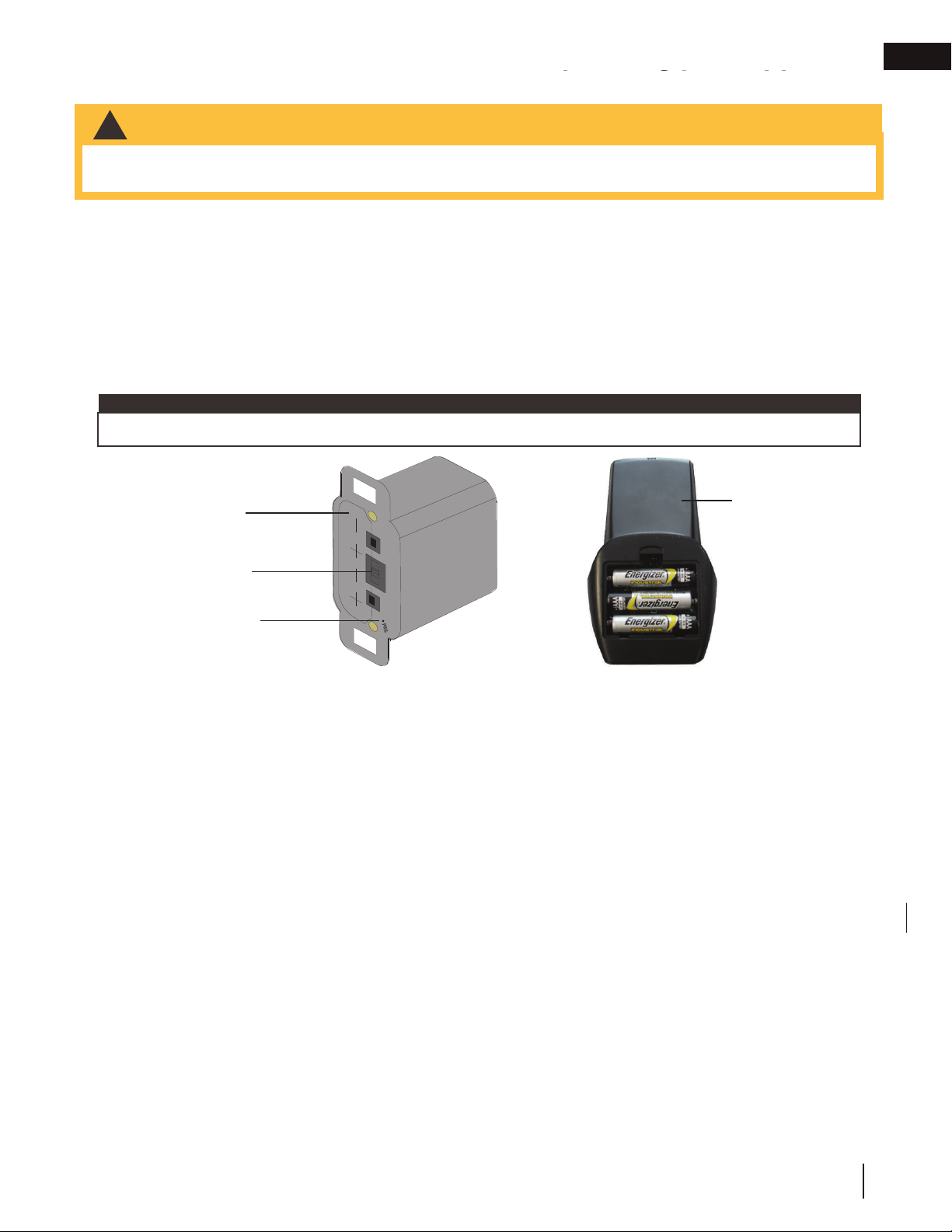
2.1 initializing the transmitter / battery holder for the fi rst time
WARNING
!
• Ensure the gas and electrical power to the appliance is turned off.
• Appliance may be hot, do not service until the appliance has cooled.
A. Install the 4 AA batteries into the Profl ame 2 battery holder, note the polarity of the batteries and insert as
indicated on the cover (+/-).
B. Ensure the 3 position slider switch is switched to the “REMOTE” position (middle position).
C. Press the reset/programming button, use a small object such as a paper clip in order to reach the button
marked PRG, as shown in the illustration below.
D. The battery holder will beep 3 times to indicate that it’s ready to synchronize with the transmitter.
E. Install the 3 AAA batteries into the transmitter, as shown in the photograph below, then press the ON
button. The battery holder will beep 4 times to indicate that the transmitter’s command is accepted.
note:
The initializing process must be completed within 10 seconds of pressing the reset/programming button (PRG).
EN
Battery Holder
(including switch)
Slider Switch
Reset / Program
Button (PRG)
(4) AA Batteries
Remote control
2.2 using your appliance
When operating your appliance for the fi rst time, there is a required burn-in process that cures materials used
to manufacture the appliance that may emit both vapors and an odor. These are normal when operating a new
appliance for the fi rst time. Ensure adequate air circulation is provided during burn-in process, if this was not
completed by the installer during installation.
To turn the appliance on:
A Turn the remote on.
B After 3-5 seconds, the control will start a spark at the pilot, light the pilot and then the burner. The spark
period will last 60 seconds, or until the pilot has lit.
C When used for the fi rst time, if the burn-in process was not completed by the installer; run appliance
continuously for minimum 4 hours (burn-in).
D Turn the appliance off. Wait until appliance is completely cool before moving to the next step.
E Remove the safety barrier, door trims and fi rebox glass door. Clean fi rebox glass door (see “maintenance”
section). Replace fi rebox glass door, door trims and safety barrier.
For more detailed information, see your installation manual or contact your authorized dealer.
W415-1939 / A / 05.07.19
7

EN
3.0 remote control layout
remote control layout
3.1 general transmitter layout
Transmission
Flame ON
Key Lock
Low battery alarm
Room
Temperature
CPI mode
Power
(ON/OFF)
Function
Adjustment
Cycle Through Functions
Blower
Remote Control
Light
note:
Install the 3 ‘AAA’
batteries into the
remote control, as
shown, then press
the ON button. The
battery holder will
beep 4 times to
indicate that the
remote’s command is
accepted.
3.2 temperature display
A. With the system in the off position, press the temperature key
and the mode key at the same time to change from degrees ºF to
ºC.
B. Look at the LCD screen on the transmitter to verify that a ºC or ºF
is visible to the right of the room temperature display.
8
W415-1939 / A / 05.07.19
°F °C
73 23

remote control layout
ADD TITLE: Night Light Dimmer Control
3.3 fl ame height
The remote control has six (6) fl ame levels. With the system on and the fl ame level at the maximum, press the
down arrow key once and it will reduce the fl ame height by one step until the fl ame is turned off.
The up arrow key will increase the fl ame height each time it is pressed. If the up arrow key is pressed while
the system is on but the fl ame is off, the fl ame will come on at the high position. A single “beep” will confi rm
reception of the command.
°F
76
76
°F
76
°F
°F
76
EN
OFF
Flame Off Flame at level 1 Flame at level 5 Flame at “Hi” level 6
3.4 blower speed
The speed of the fan can be controlled by the remote
system. The fan speed can be adjusted through six (6)
speeds.
• Use the mode key to guide you to the fan control icon.
• Use the up/down arrow keys to turn on/off or adjust the fan
speed. A single “beep” will confi rm reception of the command.
note:
When the desired blower speed is selected, the blower will automatically come on 5 minutes after the main
burner has been turned on and remain on twelve minutes after it has been turned off.
3.5 night light dimmer control
The auxiliary function controls the Night Light™ with dimmable control.
A. Use the mode key to guide you to the Night Light™ icon.
B. The intensity of the output can be adjusted through 6 levels.
Use the up/down arrow keys to adjust the output level. A single beep
will confi rm reception of the command.
Hi
76
68
OFF
°F
Hi
°F
76
°F
76
°F
76
3.6 in the event of a power failure
If the receiver is equipped with batteries they will enable fl ame height control or on/off function to control the
appliance during a power failure. Blower and Night Light™ operation is not possible. Refer to “appliance
operation” section when communications between receiver and transmitter have been lost. The receiver will
emit a “beep” sound to confi rm programming has been successful once power is restored. During a power
failure, if the appliance was on, the fl ame height will stay at the setting prior to the failure. If off when the failure
occurs and then turned on, the fl ame height will come on at “Hi”. The fl ame height can then be controlled by the
remote.
3.7 continuous pilot / intermittent pilot (CPI/IPI) selection
• When the transmitter is in the off position, use the mode key to guide
you to the CPI mode icon.
• Press the up/down to switch between IPI and CPI modes. A single
beep will confi rm reception of the command.
note:
If the appliance is equipped with a CPI/IPI* toggle switch, set the CPI/IPI
to CPI position to enable remote CPI operation. If the switch is set to IPI
then it will only work in IPI regardless of what is set on the remote control
handset.
* Some jurisdictions may prohibit the use of a standing pilot. In these jurisdictions, the CPI switch shall be
disconnected to comply with local code.
76
IPI
°F
CPI
°F
76
W415-1939 / A / 05.07.19
9
EN
remote control layout
3.8 eFIRE Controller application
Napoleon’s eFIRE application will revolutionize the way you use your fireplace! We have cracked the code and
present to you the first fireplace to be controlled by Bluetooth™ technology, using an intuitive app on your mobile
device.
When fully equipped (if applicable), the eFIRE application allows you to select from a multitude of colours to suit
your mood or décor simply by scrolling through the colour wheel. Additionally, Napoleon’s eFIRE application allows
you to control many other functions of your fireplace, including on/off, flame height, light feature, blower, and a
timer to create a schedule for your fireplace that works for you.
Using the instructions on the eFIRE Controller application website http://napoleonfireplaces.com/efire, install
the application and enjoy the features the eFIRE Controller application has to offer. *
* Visit the website or contact your authorized dealer for appliance-specific information and/or frequently asked
questions regarding features and products available with the eFIRE Controller application.
note:
The remote control is considered the master control for the appliance and can always be used to turn the
appliance off (ex. the eFIRE Controller application user, in control of the appliance, leaves the home).
3.9 low battery
The life span of the remote batteries depends on various factors: quality of the batteries,
the number of ignitions, etc.
76
When the transmitter batteries are low, a battery icon will appear on the LCD display
before all battery power is lost. When the batteries are replaced, this icon will disappear.
When the receiver batteries are low, no “beep” will be emitted from the receiver when
it receives an on/off command. This in an alert for the receiver that there’s low battery.
When the batteries are replaced the “beep” will be emitted from the receiver when the on/off key is pressed.
If the batteries of the receiver or transmitter are low, the appliance can be turned on manually by sliding the
three position slider switch on the receiver to the on position. This will bypass the remote control feature and the
appliance main burner will come on if the gas valve is in the on position.
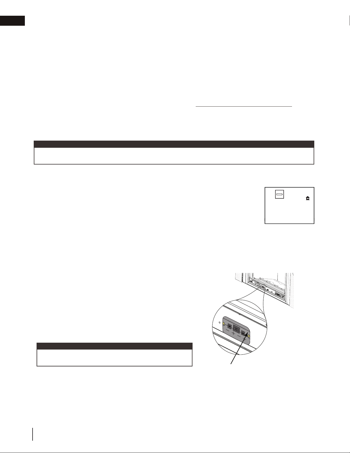
3.10 battery holder / backup installation
A. The battery holder is located in the valve compartment,
accessible for programming the remote.
B. Install 4 AA batteries, Ensure that the positive and negative
ends correspond with those identified in the battery holder.
C. In the case of a power outage, the 3 position slider switch
needs to be in the “ON” position (left).
note:
Ensure the 3 positions slider switch is in the “REMOTE”
position (middle).
(4) AA Batteries
RESET/PROGRAM BUTTON (PRG)
(
4
)
A
A
B
atte
r
i
e
s
°F
10
W415-1939 / A / 05.07.19

4.0 clearances around appliance
WARNING
!
• Your appliance, gas/electrical connections, venting and various key components are hidden behind the wall. It is
critical that no screws penetrate these components. Failure to follow instructions may cause improper operation,
damage, personal injury or fi re. Always use a stud fi nder and only screw into studs.
Without making adequate provisions to account for the heat, the temperatures above the appliance will be hot,
making it unsuitable for mounting a TV or other objects sensitive to heat without risk of damage.
Installing a mantel between this appliance and electronics or other materials that may be sensitive to heat will
reduce the effect of direct heat on them.
The size and material of the mantel will affect the allowable clearance above your appliance and incorrect
placement could become a fi re hazard. Consult your installation manual and/or authorized dealer for more
information before mounting a mantel, a shelf or any other object above your appliance.
Your appliance, gas/electrical connections and vent are hidden directly behind the fi nished wall. Great care should
be taken to avoid screwing or nailing into these components. Always use a stud fi nder to determine stud location
and only screw into studs.
Do not screw into the area around the appliance opening as some of your appliance may be hidden behind the
fi nished wall. Refer to your installation manual and/or contact your local dealer for more information.
clearances around fi replace
WARNING
!
The area above an appliance
gets hot. Combustible
objects or materials must
never be placed in this area.
For minimum clearances,
refer to installation manual or
your authorized dealer.
EN
Fireplaces
generate radiant
heat. Do not put
objects in front
of the appliance
(minimum
distance of 4 feet
[1.21m]).
W415-1939 / A / 05.07.19
11

EN
A
clearances around fi replace
Flush installation without mantel
TV bracket
Partially recessed installation with mantel
6” min.
TV bracket
2.5” min.
2” min. (7” min. recommended)
Enclosure
Top of
finishing
flange
(fireplace
Appliance
opening)
Recessed installation with protrusion
6” min.
TV bracket
2.5” min.
2” min. (3” max. recommended)
Enclosure
Top of finishing flange
(fireplace opening)
See “minimum clearance to
mantle” section (installation
Appliance
The volume of air must be added to the enclosure
to accomodate the recessed area.
manual).
Mantle clearances reduced
B
to 4” from opening with
the use of the heat management
system.
Enclosure
Appliance
A or B
Top of finishing flange
(fireplace opening)
Flush installation with mantel
6” min.
TV bracket
2.5” min.
2” min. (3” max. recommended)
Enclosure
Appliance
A
Top of finishing flange
(fireplace opening)
note:
• These are recommended minimum clearances only and are in supplied in good faith and not a guarantee
of compliance with TV manufacturers’ maximum allowable operating temperatures. Always comply to TV
manufacturers’ requirements.
• TV temperatures must be validated at the time of installation as air fl ow characteristics within the
room can vary and maximum acceptable operating temperatures can vary from appliance to appliance.
TVs cannot be used where the TV temperature exceeds the manufacturer’s maximum allowable operating
temperatures (see TV manufacturer’s specifi cations).
• Mantel height and depth must conform to mantel clearance requirements specifi ed in this manual, see
“minimum clearance to combustible mantel” section in installation manual.
• Dimension “A” the gap between the top of the fi nishing fl ange and the bottom of the TV are taken from the
top of the appliance opening.
• TV temperatures may be further reduced by increasing the horizontal distance between the front of the TV
and the front edge of the mantel or by increasing dimension “A”. However, increasing the gap between the
top of the mantel and the bottom of the TV beyond the maximum recommended fi gure, typically results in
higher temperatures. Minimum clearance between the mantel and bottom of the TV should be maintained to
allow air circulation below and behind the TV.
12
W415-1939 / A / 05.07.19
 Loading...