

Page 1
IOM
W415-1241 / A / 03.18.15
UM
PG
59
$10.00
INSTALLER: PLEASE FAMILIARIZE YOURSELF WITH VENTING/DRAINING SECTIONS OF
THIS MANUAL BEFORE PROCEEDING WITH THE INSTALLATION. LEAVE
THIS MANUAL WITH THE APPLIANCE FOR FUTURE REFERENCE.
CONSUMER: RETAIN THIS MANUAL FOR FUTURE REFERENCE.
INSTALLATION AND
OPERATING INSTRUCTIONS
Wolf Steel Ltd., 24 Napoleon Rd., Barrie, ON, L4M 0G8 Canada /
103 Miller Drive, Crittenden, Kentucky, USA, 41030
Phone (705)721-1212 • Fax (705)722-6031 • www.napoleonheatingandcooling.com • hvac@napoleonproducts.com
SAFETY INFORMATION
ELECTRICAL SHOCK, FIRE OR
EXPLOSION HAZARD
Failure to follow safety warnings exactly
could result in serious inquiry, death or
property damage.
Improper servicing could result in
dangerous operation, serious injury, death
or property damage.
- Installation and service must be performed by a
qualifi ed installer, service agency or the gas supplier.
- Before servicing, disconnect all electrical power to
furnace.
- When servicing controls, label all wires prior to
disconnecting. Reconnect wires correctly.
- Verify proper operation after servicing.
-
Do not store or use gasoline or other fl ammable
vapors and liquids in the vicinity of this or any other
appliance.
- WHAT TO DO IF YOU SMELL GAS:
• Do not try to light any appliance.
• Do not touch any electrical switch; do not use
any phone in your building.
• Leave the building immediately.
• Immediately call your gas supplier from a
neighbour’s phone. Follow the gas supplier’s
instructions.
• If you cannot reach your gas supplier, call the fi re
department.
!
WARNING
!
MANUFACTURER RESERVES THE RIGHT TO DISCONTINUE, OR CHANGE
AT ANY TIME, SPECIFICATIONS OR DESIGNS WITHOUT NOTICE AND
WITHOUT INCURRING OBLIGATIONS.
Patent Pending
H1.25A
CERTIFIED TO ANSI Z21.47-2012 / CSA 2.3-2012
9600 - B SERIES
TWO STAGE MULTI POSITION HIGH EFFICIENCY
(CONDENSING) FORCED AIR GAS FURNACE
Page 2

W415-1241 / A / 03.18.15
2
IOM
IOM
TABLE OF CONTENTS
1.0 INTRODUCTION 3
2.0 SAFETY SYMBOLS AND WARNINGS 4
2.1 SAFETY RULES 5
2.2 CODES 6
3.0 FURNACE SIZING 8
4.0 LOCATION OF UNIT 9
4.1 GENERAL GUIDELINES 9
4.2 OTHER CONSIDERATIONS 9
4.3 INSTALLATION IN UPFLOW, DOWNFLOW OR HORIZONTAL POSITIONS 10
4.4 AIR CONDITIONING 11
5.0 COMBUSTIBLE CLEARANCES 11
6.0 DUCTWORK 12
6.1 DUCTWORK STEPS 13
7.0 VENTING AND COMBUSTION PIPING 14
7.1 ACCEPTABLE MATERIALS IN CANADA 14
7.2 ACCEPTABLE MATERIALS IN UNITED STATES 14
7.3 VENT DRAIN OPTION 15
8.0 NON-DIRECT VENT FURNACE INSTALLATIONS USING INDOOR COMBUSTION AIR (ONE PIPE SYSTEM) 16
8.1 DETERMINING COMBUSTION AIR 17
8.1.1 CASE 1: FURNACE LOCATED IN A UNCONFINED SPACE 17
8.1.2 CASE 2: FURNACE LOCATED IN A CONFINED SPACE 17
8.1.3 CASE 3: FURNACE LOCATED IN A CONFINED SPACE, OUTDOOR AIR FROM ATTIC OR CRAWL SPACE 18
8.1.4 CASE 4: FURNACE LOCATED IN A CONFINED SPACE, OUTDOOR AIR DUCTED HORIZONTALLY 19
8.1.5 CONNECTION TO FURNACE NON-DIRECT VENT 19
9.0 VENTING GUIDELINES 20
9.1 VENT TERMINATION 21
9.2 IN CANADA 22
9.3 IN UNITED STATES 22
9.4 FURNACE VENTING INSTALLATIONS 23
9.4.1 NON-DIRECT VENT INSTALLATION USING INDOOR COMBUSTION AIR (ONE PIPE SYSTEM) 23
9.4.2 DIRECT VENT INSTALLATION USING OUTDOOR COMBUSTION AIR (TWO PIPE SYSTEM) 23
9.4.3 COMBUSTION AIR 23
10.0 TERMINATIONS 24
10.1 COMBUSTION AIR 24
10.2 EXHAUST 24
10.3 CONCENTRIC VENTING KIT 24
10.4 CONCENTRIC VENT TERMINATION INSTALLATION INSTRUCTIONS 24
10.5 LOCATION 24
10.6 MULTIPLE VENTING 25
11.0 ROUTING OPTIONS 28
11.1 EXHAUSTER ROTATION INSTRUCTIONS & PRESSURE SWITCH MOUNTING 28
11.2 CONDENSATE DRAINS 29
11.3 PREPARATIONS FOR VENT AND DRAINING OPTION 29
11.4 DRAIN HOSE INSTALLATION 33
11.4.1 DRAIN PIPING 33
11.4.2 PRIMING CONDENSATE TRAP 34
11.5 ALTERNATE CONDENSATE DRAIN PIPING INSTALLATION USING 1/2” PVC OR 3/4” CPVC 34
11.6 CONDENSATE NEUTRALIZERS 35
12.0 GAS SUPPLY AND PIPING 36
12.1 GAS SUPPLY 36
12.2 GAS PIPING 36
12.3 GAS INLET PRESSURE 37
12.4 LEAK TESTING 37
12.5 PURGING GAS LINES 37
13.0 CONVERSIONS 38
13.1 HIGH ALTITUDE CONVERSION 38
13.2 NATURAL TO LP GAS 38
13.3 CONVERSION STEPS 38
13.4 CHECKING THE INLET GAS PRESSURE 38
13.5 SETTING THE MANIFOLD GAS PRESSURE 39
13.6 CHECKING FURNACE INPUT 40
14.0 ELECTRICAL SPECIFICATIONS 41
14.1 ELECTRICAL WIRING AND CONNECTIONS 41
14.2 FURNACE CONNECTION 42
15.0 LOW VOLTAGE WIRING 43
15.1 SINGLE STAGE THERMOSTAT 43
15.2 TWO STAGE THERMOSTAT 43
15.3 THERMOSTAT LOCATION 43
16.0 OPTIONAL ACCESSORIES (FIELD SUPPLIED/INSTALLED) 44
16.1 ELECTRONIC AIR CLEANER 44
16.2 POWER HUMIDIFIER 44
16.3 EMERGENCY HEAT MODE 44
17.0 INITIAL STARTUP PROCEDURES 45
17.1 TO START THE FURNACE 45
17.2 TO SHUT DOWN THE FURNACE 45
17.3 SEQUENCE OF OPERATION 46
17.4 PROGRAMMABLE THERMOSTAT (OPTION) 46
Page 3
W415-1241 / A / 03.18.15
3
IOM
1.0 INTRODUCTION
NOTE: Changes, other than editorial, are denoted by a vertical line in the margin.
18.0 AIR FLOW 47
18.1 TEMPERATURE RISE CHECK 47
18.2 CALCULATING AIR FLOW 48
18.3 ADJUSTING BLOWER SPEEDS ON MODELS EQUIPPED WITH ECM 2.3 / EON BLOWER MOTORS 48
18.4 DEHUMIDIFICATION - ECM 2.3 / EON 49
18.5 SETTING BLOWER “ON” AND “OFF” TIMINGS - ECM 2.3 / EON MODELS ONLY 49
18.6 CONTINUOUS FAN OPERATION 49
19.0 MAINTENANCE AND TROUBLESHOOTING 50
19.1 AIR FILTER 50
19.2 LUBRICATION 50
19.3 TROUBLESHOOTING FLOWCHART 51
19.4 DIAGNOSTIC CODES FOR STATUS LED 52
19.5 FAULT CODE HISTORY 52
20.0 WIRE DIAGRAM FOR TWO STAGE FURNACE 53
20.1 TWO STAGE FURNACE WITH ECM 2.3 / EON 53
20.2 TWO STAGE FURNACE WITH X13 54
21.0 WARRANTY 55
22.0 REPLACEMENT PARTS LIST 56
23.0 SERVICE HISTORY 58
H1.22
IMPORTANT:
PLEASE READ THIS MANUAL CAREFULLY
AND KEEP IN A SAFE PLACE FOR FUTURE
REFERENCE BY A SERVICE TECHNICIAN.
ATTENTION:
UPFLOW VENTING RIGHT, MUST DRAIN ON
LEFT SIDE.
H4.0.5
This high effi cient gas fi red two stage condensing furnace is an upfl ow, downfl ow, horizontal left and right war
m
air furnace suitable for residential and light commercial heating applications with inputs from 40,000 to 120,000
Btu/hr.
This high effi cient furnace series is CSA certifi ed as a Category IV indirect or direct vent central forced air
furnace. When installed as a direct vent furnace, all combustion air is supplied to the furnace burners through the
air intake system. (See Section 7, “Ventilation and Combustion Piping.”)
All models may be fi red by natural or LP gas (propane), and may be fi eld converted from natural gas to LP gas
using Conversion Kit W370-0018.
The furnace is shipped completely assembled except for the condensate drain trap assembly. Please inspect
for damage when the furnace is unpacked.
Page 4

W415-1241 / A / 03.18.15
4
IOM
IOM
2.0 SAFETY SYMBOLS AND WARNINGS
H3.3.1
Understand and pay particular attention to the words DANGER, WARNING, and CAUTION and the following
defi ned symbols are used throughout this manual to notify the reader of potential hazards of varying risk levels.
DANGER
! !
INDICATES AN IMMINENTLY HAZARDOUS SITUATION WHICH, IF NOT AVOIDED, WILL
RESULT IN DEATH OR SERIOUS INJURY.
INDICATES A POTENTIALLY HAZARDOUS SITUATION WHICH, IF NOT AVOIDED,
COULD RESULT IN DEATH OR SERIOUS INJURY.
WARNING
!
!
INDICATES A POTENTIAL HAZARDOUS SITUATION WHICH, IF NOT AVOIDED, MAY
RESULT IN MINOR OR MODERATE INJURY. IT MAY ALSO BE USED TO ALERT
AGAINST UNSAFE PRACTICES.
CAUTION
!
!
H6.0
IMPORTANT:
READ THE FOLLOWING INSTRUCTIONS COMPLETELY BEFORE INSTALLING!
H3.3
WARNING
!
!
IF THE INFORMATION IN THESE INSTRUCTIONS IS NOT FOLLOWED EXACTLY, A FIRE
OR EXPLOSION MAY RESULT, CAUSING PROPERTY DAMAGE, PERSONAL INJURY OR
LOSS OF LIFE.
FOR YOUR SAFETY
DO NOT STORE OR USE GASOLINE OR OTHER FLAMMABLE VAPORS AND LIQUIDS, OR
OTHER COMBUSTIBLE MATERIALS IN THE VICINITY OF THIS OR ANY OTHER APPLIANCE.
WHAT TO DO IF YOU SMELL GAS
• DO NOT TRY TO LIGHT ANY APPLIANCE.
• DO NOT TOUCH ANY ELECTRICAL SWITCH; DO NOT USE ANY PHONE IN YOUR
BUILDING.
• IMMEDIATELY CALL YOUR GAS SUPPLIER FROM A NEIGHBOR’S PHONE, OR A CELLULAR PHONE FROM A LOCATION WELL AWAY FROM THE BUILDING. FOLLOW THE
GAS SUPPLIER’S INSTRUCTIONS.
• IF YOU CANNOT REACH YOUR GAS SUPPLIER, CALL THE FIRE DEPARTMENT.
• DO NOT RE-ENTER THE BUILDING UNTIL AUTHORIZED TO DO SO BY THE GAS
SUPPLIER OR THE FIRE DEPARTMENT.
PROPER INSTALLATION, ADJUSTMENT, ALTERATION, SERVICE OR MAINTENANCE CAN
CAUSE INJURY, PROPERTY DAMAGE OR LOSS OF LIFE. REFER TO THIS MANUAL.
INSTALLATION AND SERVICE MUST BE PERFORMED BY A QUALIFIED INSTALLER,
SERVICE AGENCY OR THE GAS SUPPLIER.
Page 5
W415-1241 / A / 03.18.15
5
IOM
2.1 SAFETY RULES
H3.4
THESE INSTRUCTIONS ARE INTENDED AS AN AID TO QUALIFIED SERVICE
PERSONNEL FOR PROPER INSTALLATION, ADJUSTMENT AND OPERATION OF
THIS FURNACE. READ THESE INSTRUCTIONS THOROUGHLY BEFORE ATTEMPTING
INSTALLATION OR OPERATION. FAILURE TO FOLLOW THESE INSTRUCTIONS MAY
RESULT IN IMPROPER INSTALLATION, ADJUSTMENT, SERVICE OR MAINTENANCE,
POSSIBLY RESULTING IN FIRE, ELECTRICAL SHOCK, CARBON MONOXIDE
POISONING, EXPLOSION, PROPERTY DAMAGE, PERSONAL INJURY OR DEATH.
WARNING
!
!
H6.1
1. Use this furnace only with type of gas approved for this furnace. Refer to the furnace rating plate.
2. Install this furnace only in dry indoor locations (protected from weather).
3. Provide adequate combustion and ventilation air to the furnace space as specifi ed in Section 7 of this
manual, “Ventilation and Combustion Piping.”
4. Combustion products must be discharged outdoors. Connect this furnace to an approved vent system only,
as specifi ed in Section 7 of this manual, “Venting and Combustion Piping.”
5. Never test for gas leaks with an open fl ame. Use a commercially available soap solution made specifi cally
for the detection of leaks to check all connections as specifi ed in Section 12 of this manual, “Gas Supply
and Piping.”
6. Always install furnace to operate within the furnace’s intended temperature-rise range with a duct system,
which has an external static pressure within the allowable range, listed on the furnace rating plate, and as
specifi ed in Sections 3, 6, and 18 of this manual, “Furnace Sizing,” “Ductwork,” and “Airfl ow.”
7. When a furnace is installed so that the supply ducts carry air circulated by the furnace to areas outside the
space containing the furnace, the return air shall also be handled by duct(s) sealed to the furnace casing and
terminating outside the space containing the furnace. (Furnace for heating the home located in the attached
garage, for example).
8. A gas-fi red furnace for installation in a residential garage must be installed so that the burners and ignitor
are no less than 18” (457 mm) above the fl oor. The furnace must be located, or protected to avoid physical
damage by vehicles. (See safety warning).
9. This furnace may be used for heating of buildings or structures under construction provided that:
• The furnace is permanently installed with all electrical wiring, piping, venting and ducting installed per
these installation instructions.
• A room thermostat must control the furnace. The use of fi xed jumpers that will provide continuous
heating is not allowed.
• The return air duct must be provided and sealed to the furnace casing, and terminate outside the
space containing the furnace.
• Return air temperature range between 55°F (13°C) and 80°F (27°C) must be maintained.
• Air fi lters must be installed in the system and must be maintained during construction.
• Air fi lters used to clean the circulating air during the construction process must be either replaced or
thoroughly cleaned prior to occupancy.
• The input rate and temperature rise must be set per the furnace rating plate.
• One hundred percent (100%) outdoor air must be provided for combustion air requirements during
construction. This is to minimize the corrosive effects of adhesives, sealers and entrainment of
drywall dust into combustion air, which can cause fouling and plugging of furnace components.
• The furnace heat exchanger, components, duct system, and evaporator coils must be thoroughly
cleaned following fi nal construction clean-up.
• All furnace operating conditions (including ignition, input rate, temperature rise and venting) must be
verifi ed according to these installation instructions.
Page 6
W415-1241 / A / 03.18.15
6
IOM
IOM
2.2 CODES
H6.2
1. This furnace must be installed:
a. In accordance with all local codes, by-laws and regulations by those authorities having jurisdiction.
b. In Canada, this furnace must be installed in accordance with the current CAN/CGA -B149.1 and .2
Natural Gas and Propane, and the National Electric Code (NEC) NFPA 70.
c. In the United States, this furnace must be installed in accordance with the current ANSI Z223.1 (NFPA
54) National Fuel Gas Code.
2. Electrical connections must be made in accordance with:
a. Any applicable local codes, by-laws and regulations.
b. Canada: current edition of CAN/CSA C22.1 and C22.2, Canadian Electrical Code (Part 1 and 2).
c. United States: current edition of ANSI/NFPA 70, National Electrical Code.
Codes and additional information may be obtained from:
Canadian Standards Association American Gas Association
5060 Spectrum Way 400 North Capitol Street, NW, Suite 450
Mississauga, Ontario, L4W 5N6 Washington DC, 20001
Phone: (416) 747-4000 Phone: (202) 824-7000
website: www.csa.ca website: www.aga.org
National Fire Protection Association
1 Batterymarch Park
Quincy, MA, 02169-7471
Phone: (617) 770-3000
website: www.nfpa.org
H3.5
DO NOT INSTALL THIS FURNACE IN A MOBILE HOME! THIS FURNACE IS NOT
APPROVED FOR INSTALLATION IN A MOBILE HOME. DOING SO COULD CAUSE FIRE,
PROPERTY DAMAGE, PERSONAL INJURY OR LOSS OF LIFE.
THE FURNACE CONTAINS FOIL COVERED FIBERGLASS INSULATION. INHALATION OF
FIBERGLASS PARTICLES IS ASSOCIATED WITH RESPIRATORY DISEASE INCLUDING
CANCER.
NATURAL GAS AND PROPANE ARE NORMALLY ODORIZED BY THE FUEL SUPPLIER. IN
SOME CASES, THE ODORANT MAY NOT BE PERCEIVABLE. INSTALLATION OF UL AND
ULC RECOGNIZED FUEL GAS DETECTORS INSTALLED IN ACCORDANCE WITH THEIR
MANUFACTURER’S INSTRUCTIONS IS RECOMMENDED AS AN ADDITIONAL MARGIN OF
SAFETY.
THE EXHAUST GASES FROM THIS FURNACE CONTAIN CHEMICALS WHICH ON
SOME OCCASIONS MAY INCLUDE CARBON MONOXIDE. CARBON MONOXIDE IS AN
ODORLESS, TASTELESS, CLEAR COLORLESS GAS WHICH IS HIGHLY TOXIC. EVEN
LOW CONCENTRATIONS ARE SUSPECTED OF CAUSING BIRTH DEFECTS AND OTHER
REPRODUCTIVE HARM.
UL AND ULC RECOGNIZED CO DETECTORS ARE RECOMMENDED FOR ALL BUILDINGS
EQUIPPED WITH FOSSIL FUEL BURNING APPLIANCES. ALL CO DETECTORS SHOULD
BE INSTALLED IN ACCORDANCE WITH THEIR MANUFACTURER’S INSTRUCTIONS AND
APPLICABLE LOCAL BUILDING CODES.
FIRE, EXPLOSION OR CARBON MONOXIDE POISONING HAZARD!
FAILURE TO REPLACE WITH PROPER CONTROL COULD RESULT IN FIRE, EXPLOSION
OR CARBON MONOXIDE POISONING.
REPLACE GAS VALVE ONLY WITH THE SAME MODEL NUMBER OR AS SPECIFIED BY THE
MANUFACTURER.
WARNING
!
!
Page 7
W415-1241 / A / 03.18.15
7
IOM
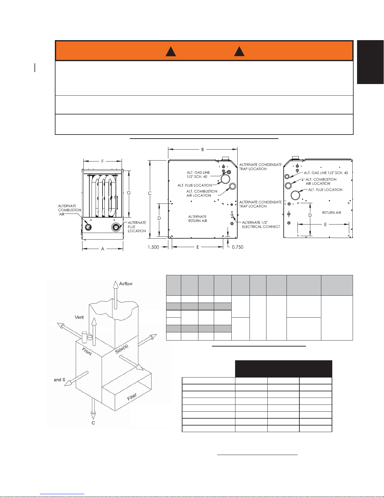
FIGURE 1 - FURNACE DIMENSIONS AND CLEARANCE TO COMBUSTIBLES
TOP LEFT SIDE RIGHT SIDE
0"
Top
NOTES:
S - Service clearance 24 inches (610mm) or more.
C - Combustible oor (but not carpet or non-ceramic tile).
All models approved for closet installation.
Plenum
1/2" (13mm)
on all sides
0"
0"
0"
0"
H3.6A
WARNING
!
!
WHEN THIS FURNACE IS INSTALLED IN A STORAGE GARAGE, IT MUST BE INSTALLED
SO THE BURNERS AND IGNITION SOURCE ARE LOCATED NO LESS THAN 18” (457 mm)
ABOVE THE FLOOR TO PREVENT THE RISK OF IGNITING FLAMMABLE VAPORS WHICH
MAY BE PRESENT IN THE GARAGE.
THE FURNACE MUST BE LOCATED OR PROTECTED TO AVOID PHYSICAL DAMAGE BY
VEHICLES.
FAILURE TO HEED THESE WARNINGS CAN CAUSE A FIRE OR EXPLOSION, RESULTING
IN PROPERTY DAMAGE, PERSONAL INJURY OR LOSS OF LIFE.
TABLE A - FURNACE DIMENSIONS
INPUT
OUTPUT
HIGH
INPUT
LOW
OUTPUT
LOW Width Depth Height Supply Air Return Air
K/Btu/hr K/Btu/hr K/Btu/hr K/Btu/hr A B C (F x G) (D x E)
40 38 24 23
17 1/2"
(445mm)
29 1/2"
(749mm)
32 7/8"
(835mm)
16 1/2" x 19 5/8"
(419mm x 499mm)
14" x 23"
(356mm x 584mm)
60 57 36 34
80-3*
77 48 46
80-4**
22 1/2"
(572mm)
21 1/2" x 19 5/8"
(546mm x 499mm)
100 96 60 58
120 115 72 69
NOTE: * 3 TON, ** 4 TON
H12.11.2
UPFLOW DOWNFLOW HORIZONTAL
TOP 0 0 0
PLENUM TOP 1/2" (13mm) 0 1/2" (13mm)
FRONT 0* 0* 0*
BACK 0 0 0
SIDES 0 0 0**
BOTTOM 0*** 0 0
FLUE PIPE 0 0 0
ENCLOSURE CLOSET CLOSET CLOSET
TABLE B - MINIMUM CLEARANCES TO COMBUSTIBLE MATERIALS
*24" (610mm) REQUIRED FOR SERVICE
**SUPPLY AIR OUTLET / 1/2" (13mm) RETURN AIR INLET
*** CERTIFIED FOR CLOSET INSTALATION ON COMBUSTIBLE FLOORING.
TABLEAU B - DÉGAGEMENTS MINIMAUX AUX MATÉRIAUX COMBUSTIBLES
Page 8

W415-1241 / A / 03.18.15
8
IOM
IOM
3.0 FURNACE SIZING
H7.0.3
The maximum hourly heat loss for each heated space shall be calculated in accordance with the procedures
described in the manuals of the Heating, Refrigeration and Air Conditioning Institute of Canada (HRAI), or
by any other method which is suitable for local conditions, provided the results obtained are in substantial
agreement with, and not less than those obtained using the procedure described in their manuals.
In the United States, “Manual J - Load Calculation,” published by the Air Conditioning Contractors of America,
describes a suitable procedure for calculating the maximum hourly heat loss.
If the installation is a retrofi t application, do not rely on the capacity of the existing heating equipment as a
method to size the new furnace. Many of the heat transfer multiples listed in earlier versions of load calculation
manuals were much higher than those listed in more recent editions. It is possible that energy saving
measures have been completed since the installation of the existing furnace. This might include additional
insulation in the attic or walls, the application of sprayed foam insulation, the addition of storm windows and
doors, weather-stripping, caulking, etc.
Many of the older furnaces were equipped with large belt drive blower systems, operating at low RPM’s. If
replacing an existing furnace, be sure that the existing ductwork can handle the amount of airfl ow necessary
for a reasonable temperature rise. Most older gas furnaces operated with a system temperature rise of 70 100°F (39 - 56°C). This furnace is designed to be operated with a system temperature rise (∆T) of High Fire
35 - 65°F (20 - 36°C), Low Fire 25 - 55°F (14 - 31°C). If
the furnace selected has an identical output capacity as the
original furnace, a substantial increase in system air fl ow will
be necessary. See Table 1 and the airfl ow characteristics in
Section 18 of this manual, “Airfl ow”.
Existing ductwork should be assessed for its air handling
capabilities.
The “Equal Friction Chart,” as published by ASHRAE and HRAI, is the basis for the various air duct
calculators available through heating supply companies. Following the air velocity guide lines, according to
the “Equal Friction Chart,” or a slide rule air duct calculator, a typical 6" (152mm) round duct has a capacity of
approximately 100 cfm.
NOTE:
The return air system is equally as important as the supply air system. An under-sized return air system
will prevent suffi cient quantities of air from reaching the supply air system and will consequently reduce
the service life of the furnace and its components.
TABLE 1 - RANGE OF TEMPERATURE RISE
Furnace Models Temperature Rise
ALL
High Fire (HF) 35 - 65°F (20 - 36°C)
Low Fire (LF) 25 - 55°F (14 - 31°C)
H12.15.3
Page 9
W415-1241 / A / 03.18.15
9
IOM
4.0 LOCATION OF UNIT
4.1 GENERAL GUIDELINES
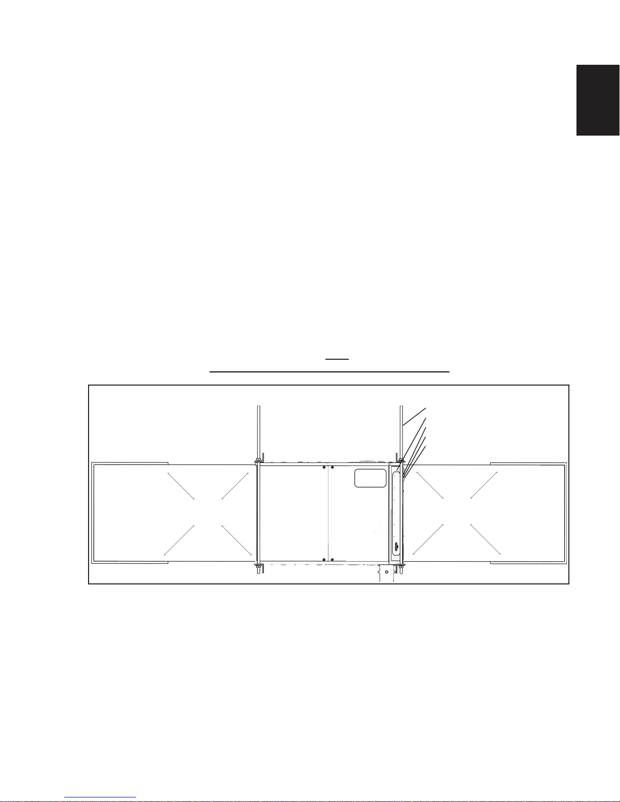
FIGURE 3 - SUGGESTED METHOD FOR SUSPENDING HORIZONTAL FURNACE
RETURN AIR PLENUM
ALLOW ENOUGH ANGLE
IRON OVERHANG TO PERMIT
OPENING THE BLOWER DOOR.
• 3/8” THREADED ROD
• 2” ANGLE IRON
• JAM NUTS
• LOCK WASHER
• FLAT WASHER
SUPPLY AIR PLENUM
4.2 OTHER CONSIDERATIONS
H8.1.2
1. Select a location where the exhaust and combustion air piping can be routed between the furnace and
their terminations with a minimum of lengths and fi ttings. Be sure to check that the proposed termination
location will meet code requirements with respect to location and minimum clearances. (See venting
section for minimum and maximum limits.)
2. Select a location as near as possible to the existing or proposed duct system.
3. The furnace location must have provisions for condensate drainage. If a suitable drain is unavailable near
the furnace, a condensate pump must be used. The condensate pump drain tubing must not terminate
outdoors; similar to some air conditioning condensate installations. Be sure to select a condensate pump
that has been approved for furnace condensate applications.
4. The furnace location must permit access for servicing and be within the clearance to combustibles
guidelines as marked on the appliance rating plate.
5. The furnace must be installed on a level surface. It is recommended that the rear of the furnace be
elevated 1/4" (6mm) higher than the front to facilitate proper condensate drainage.
6. If the furnace is being installed so that the return air will enter through the bottom, the perimeter of the
furnace must be properly supported.
7. When installed in the horizontal position, the furnace may be supported from the bottom, or suspended.
(Figure 3)
8. In upfl ow right venting confi guration, furnace must drain on the left side.
1. If the furnace is to be located in an area where the combustion air is laden with chemical compounds such
as bromine, chlorine or fl uorine, as may be found in swimming pool chemicals, laundry detergents, etc.,
use outdoor air for combustion. These compounds when exposed to fl ame, form acids which attack the
heat exchanger and other components.
Exposure to the following substances in the combustion air supply (but not limited to the following) will also
require OUTDOOR AIR for combustion:
• Aerosols, particularly CFC based or propelled aerosols
• Air fresheners
• “Airplane Glue” and similar adhesives and cements
Page 10
W415-1241 / A / 03.18.15
10
IOM
IOM
4.3 INSTALLATION IN UPFLOW, DOWNFLOW OR HORIZONTAL POSITIONS
H8.2
• Ammonia, as commonly found in permanent wave solutions used in hair dressing salons
• Anti-static fabric softeners used in clothes dryers
• Carbon tetrachloride
• Chlorinated cleaners and waxes
• Chlorine and bromine based swimming pool chemicals
• De-icing salts or chemicals (rock salt, etc.)
• Dry cleaning fl uids such as perchloroethylene
• Fumes from curing polyurethane and similar substances
• Halogen based refrigerants including R-12 and R-22
• Hydrochloric acid, muriatic acid and other acid based masonry washing and curing materials
• Printer’s inks, paint removers, varnishes, varsol, toluene, etc.
• Water softener salt and chemicals
2. If this furnace is to be installed in an area over a fi nished ceiling or living area, install a fi eld fabricated
auxiliary drain pan under the furnace to protect that area from accidental condensate spills. The auxiliary
pan should be large enough to collect accidentally spilled condensate from the air conditioning evaporator
coil assembly if applicable.
3. If the furnace is installed in an area where freezing may occur, a garage, an attic, a crawl space or any
unconditioned space, steps must be taken to protect the condensate trap and drain line from freezing.
H8.3.2
UPFLOW INSTALLATION: Vent positioning, pressure switch location and drain locations shall be performed in
accordance with instructions in the appropriate sections of this manual.
HORIZONTAL INSTALLATION: Vent positioning, pressure switch location and drain locations shall be performed in
accordance with instructions in the appropriate sections of this manual.
NON-SUSPENDED INSTALLATION: Maintain clearances to combustibles as outlined in Table B. The furnace
must be supported in such a way as to not allow twisting or sagging of the cabinet.
SUSPENDED INSTALLATION: Maintain clearances to combustibles as outlined in Table B. The furnace may
be suspended by fi eld fabricating a cradle of angle iron and threaded rod. Secure the furnace with 2” (51mm)
minimum slotted angle or equivalent as shown in Figure 3. The furnace must be supported in such a way as to
not allow twisting or sagging of the cabinet. Position the supports so as to not interfere with accessing the burner
and blower compartments.
DOWNFLOW INSTALLATION: Vent positioning, pressure switch location and drain locations shall be performed
in accordance with instructions in the appropriate sections of this manual.
The opening in the fl oor must provide adequate clearances to the combustible material according to the
clearance to combustible as outlined in Table B.
IMPORTANT:
• THE FURNACE MUST BE INSTALLED ON A LEVEL SURFACE. IT IS RECOMMENDED
THAT THE REAR OF THE FURNACE BE ELEVATED 1/4” (6mm) HIGHER THAN THE
FRONT TO FACILITATE PROPER CONDENSATE DRAINAGE.
• IF THE FURNACE AND AIR CONDITIONER IS LOCATED ABOVE A FINISHED SPACE,
INSTALL A DRAIN PAN UNDERNEATH THE UNIT.
NOTE
This furnace is approved for installation in attics, alcoves, utility rooms, closets and crawl spaces. If this
furnace is to be installed in a utility room, be sure that it is located in such a way as to allow access for
servicing or the removal of other appliances installed in the room (hot water heater, for example). It is not
permissible to use a rear return on this appliance. Use only side and bottom returns.
Page 11
W415-1241 / A / 03.18.15
11
IOM
4.4 AIR CONDITIONING
5.0 COMBUSTIBLE CLEARANCES
H8.4.3
This furnace may be used as part of an air conditioning system. The furnace wiring and control system is “air
conditioning ready.” There are the following factors to consider:
The air conditioning evaporator coil must be downstream of the
heat exchanger. The cooled air passing over the warmer heat
exchanger tubes can cause condensation inside the tubes,
resulting in corrosion and premature failure.
A parallel duct system can be installed to direct the air from the
furnace through the evaporator coil only. Use dampers or other
means to bypass the heat exchanger. If (summer/winter) dampers
are used, they should be interlocked to prevent system operation
unless the dampers are in the full open or full closed position.
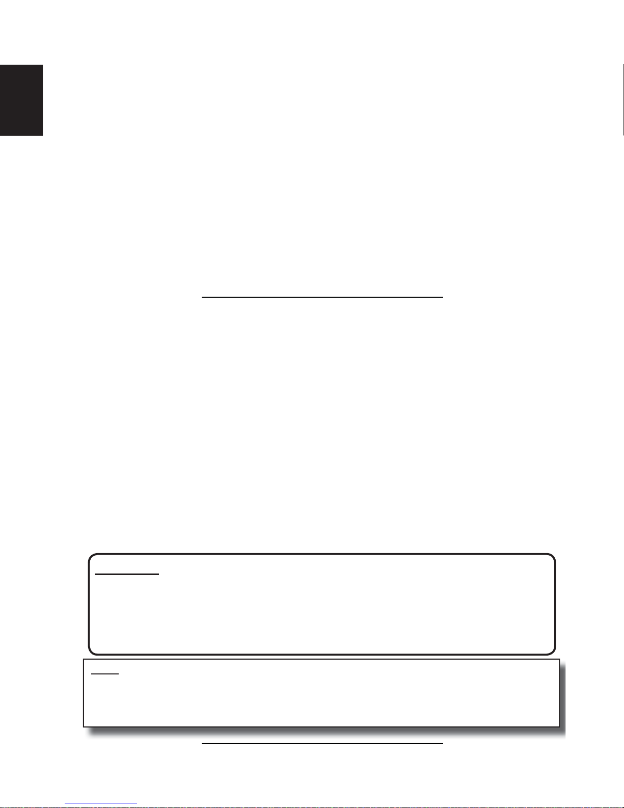
NOTE
If installing a two stage air
conditioning system, clip the JW38
jumper wire between Y (low cool)
and Y2 (high cool) on the furnace
control board.
Control defaults to Y2 (high cool) if
JW38 jumper wire is NOT cut.
H9.0
Table B provides the certifi ed clearances to combustibles information. Also see the appliance rating plate
affi xed to the furnace for specifi c model number, serial number and clearance to combustibles information.
IMPORTANT:
THIS FURNACE REQUIRES A MINIMUM OF 24" (610mm) OF FRONT CLEARANCE FOR
SERVICE PURPOSES. FOR THIS PURPOSE, SERVICE CLEARANCE TAKES PRECEDENCE OVER CLEARANCE TO COMBUSTIBLES.
H3.7
THIS FURNACE IS CERTIFIED FOR INSTALLATION ON COMBUSTIBLE FLOORS. THIS
SHALL BE INTERPRETED AS A WOOD FLOOR ONLY.
THE FURNACE MUST NOT BE INSTALLED DIRECTLY ON CARPETING, OR OTHER
COMBUSTIBLE MATERIAL EXCEPT WOOD.
INSTALLATION ON COMBUSTIBLE MATERIAL CAN RESULT IN FIRE, CAUSING PROPERTY
DAMAGE, PERSONAL INJURY OR DEATH.
THE AREA AROUND THE FURNACE MUST BE KEPT CLEAR AND FREE OF ALL
COMBUSTIBLE MATERIALS INCLUDING GASOLINE AND OTHER FLAMMABLE VAPORS
AND LIQUIDS.
THE HOMEOWNER SHOULD BE CAUTIONED THAT THE FURNACE AREA MUST NOT BE
USED AS A CLOSET OR FOR ANY OTHER STORAGE PURPOSE.
WARNING
! !
Page 12
W415-1241 / A / 03.18.15
12
IOM
IOM
6.0 DUCTWORK
H10.0
Proper airfl ow is required for the correct operation of this furnace. Insuffi cient airfl ow may cause erratic
operation, could cause the furnace to cycle on the high temperature limit, and may damage the heat
exchanger. Excessive airfl ow may result in an excessively noisy duct system and may result in undesirable
consequences such as creating uncomfortable drafts.
If air conditioning is to be used with the furnace, the duct system must be capable of delivering the correct
amount of airfl ow for each system.
The ductwork should be sized and constructed in accordance with accepted industry standards. Duct sizing
and construction information may be obtained from:
• A.C.C.A. (Air Conditioning Contractors of America)
• A.S.H.R.A.E. (American Society of Heating, Refrigeration and Air Conditioning Engineers)
• H.R.A.I. (Heating, Refrigerating and Air Conditioning Institute (Canada)
• S.M.A.C.N.A. (Sheet Metal and Air Conditioning Contractors’ National Association (United States)
All of the above professional organizations have duct sizing manuals available.
The total static pressure drop of the air distribution system (including fi lters) should not exceed 1.0” w.c.
H3.8
DO NOT ALLOW GAS PIPING TO BE ROUTED THROUGH JOIST SPACES THAT ARE
USED FOR RETURN AIR PURPOSES. DO NOT USE JOIST SPACES FOR RETURN AIR
PURPOSES IF THE JOIST SPACE ALREADY CONTAINS PLUMBING STACKS, CHIMNEY
COMPONENTS, ETC. UNLESS THE PORTION USED FOR RETURN AIR PURPOSES CAN
BE COMPLETELY ISOLATED FROM PORTIONS WITH OTHER USAGES.
NEVER ALLOW THE PRODUCTS OF COMBUSTION FROM THE FLUE TO ENTER THE
RETURN AIR OR SUPPLY AIR DUCTWORK.
ALL RETURN AIR DUCTWORK MUST BE ADEQUATELY SEALED AND SECURED TO
THE FURNACE WITH SHEET METAL SCREWS. TAPE THE SHEET METAL SEAMS IN THE
VICINITY OF THE FURNACE WITH DUCT TAPE OR SIMILAR MATERIAL.
WHEN THE FURNACE IS MOUNTED ON A PLATFORM WITH RETURN AIR THROUGH THE
BOTTOM, IT MUST BE SEALED AIR TIGHT BETWEEN THE FURNACE AND THE RETURN
AIR PLENUM. THE FLOOR OR PLATFORM MUST PROVIDE SOUND PHYSICAL SUPPORT
OF THE FURNACE WITHOUT SAGGING OR GAPS AROUND THE BASE. IT MUST ALSO
BE SEALED BETWEEN THE SUPPORT AND THE BASE.
FAILURE TO PREVENT PRODUCTS OF COMBUSTION FROM BEING CIRCULATED INTO
THE LIVING SPACE CAN CREATE POTENTIALLY HAZARDOUS CONDITIONS, INCLUDING
CARBON MONOXIDE POISONING THAT COULD RESULT IN PERSONAL INJURY OR
DEATH.
WARNING
!
!
Page 13
W415-1241 / A / 03.18.15
13
IOM
6.1 DUCTWORK STEPS
H10.1
1. Position the furnace to minimize ductwork length and fi ttings.
2. Cut open a return air inlet. The choices are furnace bottom, either side, or any combination thereof (i.e.,
two sides or a side and the bottom).In all cases, cut the return air opening the full width of the return air
markers on the side panel.
NOTE: If the airfl ow requirements exceed 1800 cfm, models will require air openings and fi lters on:
• both sides, OR
• one side and the bottom, OR
• just the bottom
3. Connect the return air duct or fi lter fi tting to the furnace. The connection should be sealed air tight to prevent
entraining combustion gases from an adjacent fuel burning appliance, or entraining combustion air for this
furnace or adjacent fuel burning appliances.
4. Ensure that there is adequate space and accessibility for air fi lter removal.
5. If an air conditioning evaporator coil is required, position it on the supply air side of the furnace. Ensure
that no air can bypass the evaporator coil.
6. Connect the supply air plenum to the supply air outlet.
FLEXIBLE DUCT CONNECTORS are an effective device to prevent the telegraphing of mechanical noise from
the furnace to other parts of the home via the ductwork. If using fl exible connectors, ensure that the adjoining
duct is independently supported.
H3.9
DO NOT USE THE REAR PANEL AS A RETURN AIR INLET. THERE IS INSUFFICIENT
ROOM TO PERMIT ADEQUATE AIRFLOW.
DAMAGES, DEFECTS OR FAILURES CAUSED BY CONDITIONED AIR (RETURN AIR)
SUPPLIED TO THE FURNACE BEING GREATER THAN 20% FROM OUTDOORS (55°F/13°C
MIN. RETURN AIR TEMPERATURE).
SOME HEATING AIR FLOW VALUES MAY BE HIGHER THAN THOSE REQUIRED FOR
COOLING. BE SURE TO SIZE DUCT SYSTEM FOR HIGHEST POSSIBLE VALUES.
WARNING
!
!
Page 14

W415-1241 / A / 03.18.15
14
IOM
IOM
7.2 ACCEPTABLE MATERIALS IN UNITED STATES
7.0 VENTING AND COMBUSTION PIPING
7.1 ACCEPTABLE MATERIALS IN CANADA
H3.10
READ, UNDERSTAND AND FOLLOW ALL INSTRUCTIONS IN THIS SECTION. FAILURE TO
PROPERLY VENT OR SUPPLY COMBUSTION AIR TO THIS FURNACE CAN CAUSE CAR-
BON MONOXIDE POISONING, OR AN EXPLOSION OR FIRE, RESULTING IN PROPERTY
DAMAGE, PERSONAL INJURY OR LOSS OF LIFE.
WARNING
!
!
H11.1A
Effective August 1, 2007, all vent piping materials and fi ttings for fl ue gas venting must be ULC S636 listed
and identifi ed as such on the material. The fi rst 3ft. (900mm) of venting must be readily available for visual
inspection. Specifi ed primers and glues of the certifi ed vent system must be from a single system manufacture,
and not intermixed with other system manufacture’s vent system parts. The components of the certifi ed vent
system must not be interchanged with other vent systems, or unlisted pipe, and or fi ttings. Follow the venting
manufacturers instructions on installation, cutting, de-burring, cementing, curing and supporting of the venting
system.
Furnace must be vented with ULC S636 certifi ed PVC manufactured by IPEX, or ULC S636 certifi ed PPE
manufactured by M&G Duravent.
PVC vent terminations may use concentric kits listed in section 10.3 - or terminate using 45 and 90 degree
elbows.
PPE venting must terminate using 45 and 90 degree elbows.
Minimum rating of 149 degrees F (65°C).
H11.2A
Furnace venting may be comprised of:
• Schedule 40 PVC, ASTM D1785 or CSA B137.3
• PVC-DWV, ASTM D2665 or CSA B181.2
• Schedule 40 CPVC, ASTM F441 or CSA B137.6
• PVC PRIMER AND SOLVENT CEMENT: ASTM D2564
• PPE ULC S636 Manufactured by M&G Duravent - must terminate using 45 and 90 degree elbows.
Follow piping manufacturers instructions on proper installation of piping and fi ttings including cutting, deburring
,
priming, cementing, curing and supporting.
Page 15
W415-1241 / A / 03.18.15
15
IOM
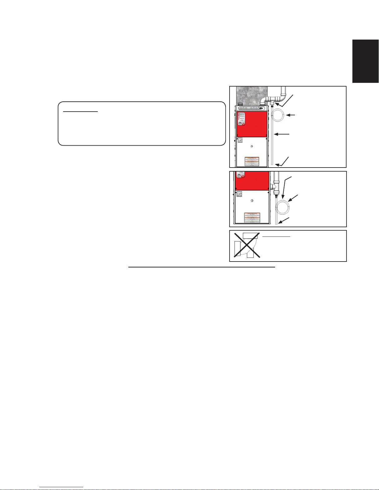
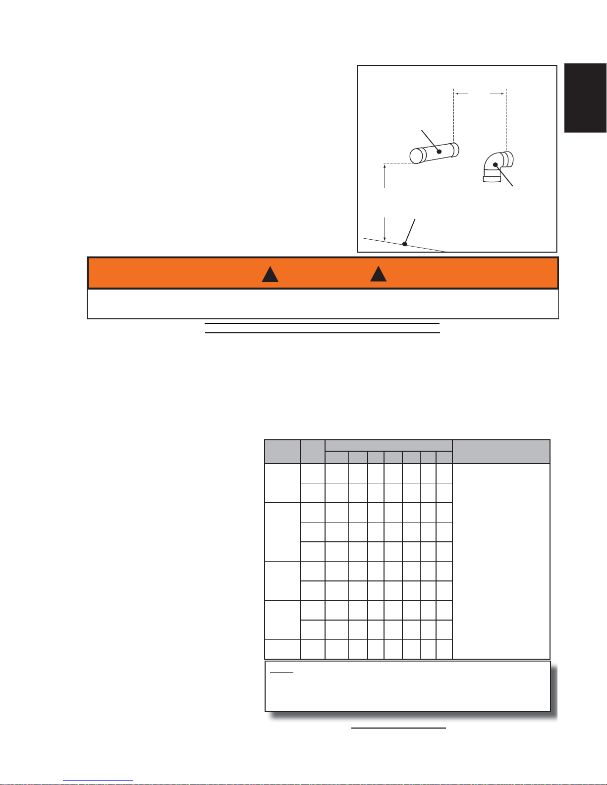
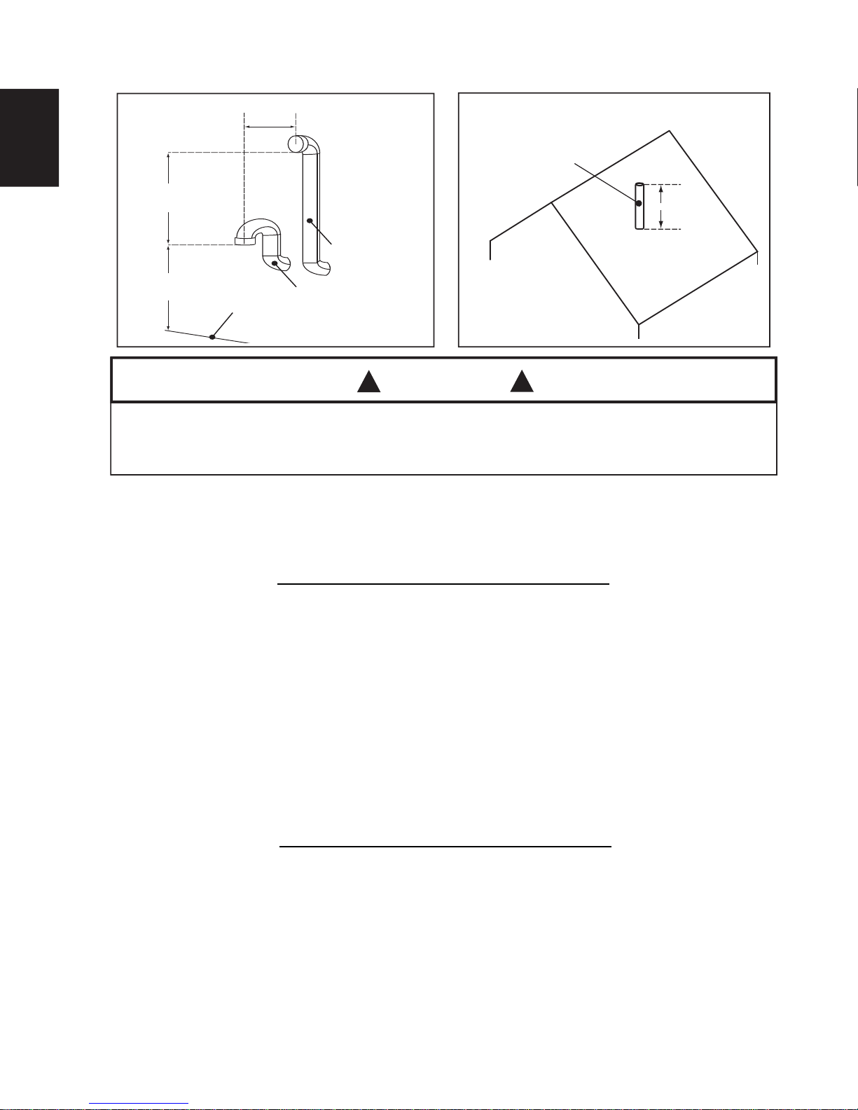
7.3 VENT DRAIN OPTION
H11.3
A vent drain is recommended when vent passes through any unconditioned space such as an attic or crawl
space in order to prevent the accumulation of excess condensate in the inducer housing during operational
cycles, refer to images for Vent Drain Option.
To install the vent drain, complete the following steps:
IMPORTANT: Tee, reducer and nipple must be properly
cemented together using the appropriate method
and materials specifi ed in section 7.0 Venting and
Combustion Piping; 7.1 Acceptable Materials in Canada
and 7.2 Acceptable Materials in United States.
1. Place a tee of the proper diameter for the vent system
being installed 2" (51mm) or 3" (76mm) in the horizontal run
or vertical riser closest to the furnace.
2. Place a reducer bushing of proper diameter in the stem
portion of the tee. The recommended size for the reducer is
5/8" (15.9mm).
3. Place a piece of 5/8" (15.9mm) diameter pipe that has a
minimum length of 3" (76mm) long into the reducer to serve
as a nipple.
4. Connect a piece of fl exible drain tubing such as EPDM
rubber or PVC to the nipple.
5. Loop the drain tubing to provide a trap.
6. Connect the discharge end of the drain tube to the
condensate disposal system externally to the furnace.
IMPORTANT:
ELBOWS WITH DRAIN PORTS
ARE NOT RECOMMENDED, AS
CONDENSATE CAN BYPASS THE
DRAIN ON THE CURVE.
1/2" (12.7mm) ID MAX.
3" (76mm) MIN.
10" (254mm) MAX.
LOOP DIAMETER
ATTACH THIS END TO
CONDENSATE DRAIN
SYSTEM
3" (76mm) MIN.
10" (254mm) MAX.
LOOP DIAMETER
ATTACH THIS END TO
CONDENSATE DRAIN
SYSTEM
1/2" (12.7mm) ID MAX.
USE SWEEP TEE ON
HORIZONTAL LINE
Page 16
W415-1241 / A / 03.18.15
16
IOM
IOM
8.0 NON-DIRECT VENT FURNACE INSTALLATIONS
USING INDOOR COMBUSTION AIR (ONE PIPE
SYSTEM)
H13.0
The furnace, although designed as a direct vent type appliance, may be installed with the intake vent inside th
e
structure.
Adequate provisions for combustion and ventilation air must be in accordance with CAN/CGA-B149 in Canada,
and ANSI Z223.1 - 1992, section 5.3, “Air for Combustion and Ventilation,” in the United States. Check with
local authorities for any additional building codes bylaws or regulations.
AIR FOR COMBUSTION AND VENTILATION PURPOSES MUST NOT ORIGINATE FROM A
CORROSIVE ATMOSPHERE. ANY FURNACE FAILURE CAUSED BY CORROSIVE ELEMENTS IS
EXCLUDED FROM WARRANTY COVERAGE.
CAUTION
!
!
The following types of installation sites (but not limited to the following) will REQUIRE OUTDOOR AIR for
combustion because of chemical exposures:
• Commercial buildings
• Buildings with indoor swimming pools
• Furnaces installed in laundry rooms
• Furnaces in hobby or craft rooms
• Furnaces installed near chemical storage areas
Exposure to the following substances in the combustion air supply (but not limited to the following) will also
require OUTDOOR AIR for combustion:
• Aerosols, particularly CFC based or propelled aerosols
• Air fresheners
• “Airplane Glue” and similar adhesives and cements
• Ammonia, as commonly found in permanent wave solutions used in hair dressing salons
• Anti-static fabric softeners used in clothes dryers
• Carbon tetrachloride
• Chlorinated cleaners and waxes
• Chlorine and bromine based swimming pool chemicals
• De-icing salts or chemicals (rock salt, etc.)
• Dry cleaning fl uids such as perchloroethylene
• Fumes from curing polyurethane and similar substances
• Halogen based refrigerants including R-12 and R-22
• Hydrochloric acid, muriatic acid and other acid based masonry washing and curing materials
• Printer’s inks, paint removers, varnishes, varsol, toluene, etc.
• Water softener salt and chemicals
Combustion air must be free of acid forming chemicals such as sulphur, fl uorine and chlorine. These elements
are found in aerosol sprays, detergents, bleaches, cleaning solvents, air fresheners, paint and varnish
removers, refrigerants, and many other commercial and household products. When burned in a gas fl ame,
vapors from these products form acid compounds. Acid compounds increase the dew point temperature of the
fl ue products and are highly corrosive after they condense.
H3.11
THIS FURNACE AND ANY OTHER FUEL BURNING APPLIANCE MUST BE PROVIDED
WITH ENOUGH FRESH AIR FOR PROPER COMBUSTION AND VENTILATION OF THE
FLUE GASES. MOST HOMES WILL REQUIRE THAT OUTSIDE AIR BE BROUGHT TO
THE FURNACE AREA. FAILURE TO DO SO CAN CAUSE PERSONAL INJURY, OR DEATH
FROM CARBON MONOXIDE POISONING.
WARNING
!
!
Page 17
W415-1241 / A / 03.18.15
17
IOM
8.1 DETERMINING COMBUSTION AIR
8.1.1 CASE 1: FURNACE LOCATED IN A UNCONFINED SPACE
8.1.2 CASE 2: FURNACE LOCATED IN A CONFINED SPACE
H13.1
Unconfi ned space does not necessarily mean that ventilation will not have to be introduced from the outdoors,
particularly in airtight homes. The minimum requirement for unconfi ned space is a volume of 50 cubic feet (1.42
m³) for each 1000 Btu/hr for all fuel burning appliances located within the unconfi ned area.
If the amount of combustion and ventilation air is insuffi cient to properly operate the furnace and other fuel
burning appliances within the unconfi ned area, it will be necessary to supply it from the outdoors based on the
criteria used when calculating the air supply for a confi ned space.
NOTE
If planning to use the inside air in an unconfi ned space, remember to test for proper furnace operation (as well
as other fuel burning appliances located within the unconfi ned space) with respect to adequate combustion and
ventilation air with fi replace dampers open, clothes dryer running, bathroom exhaust fans on, kitchen range hood
on, etc.
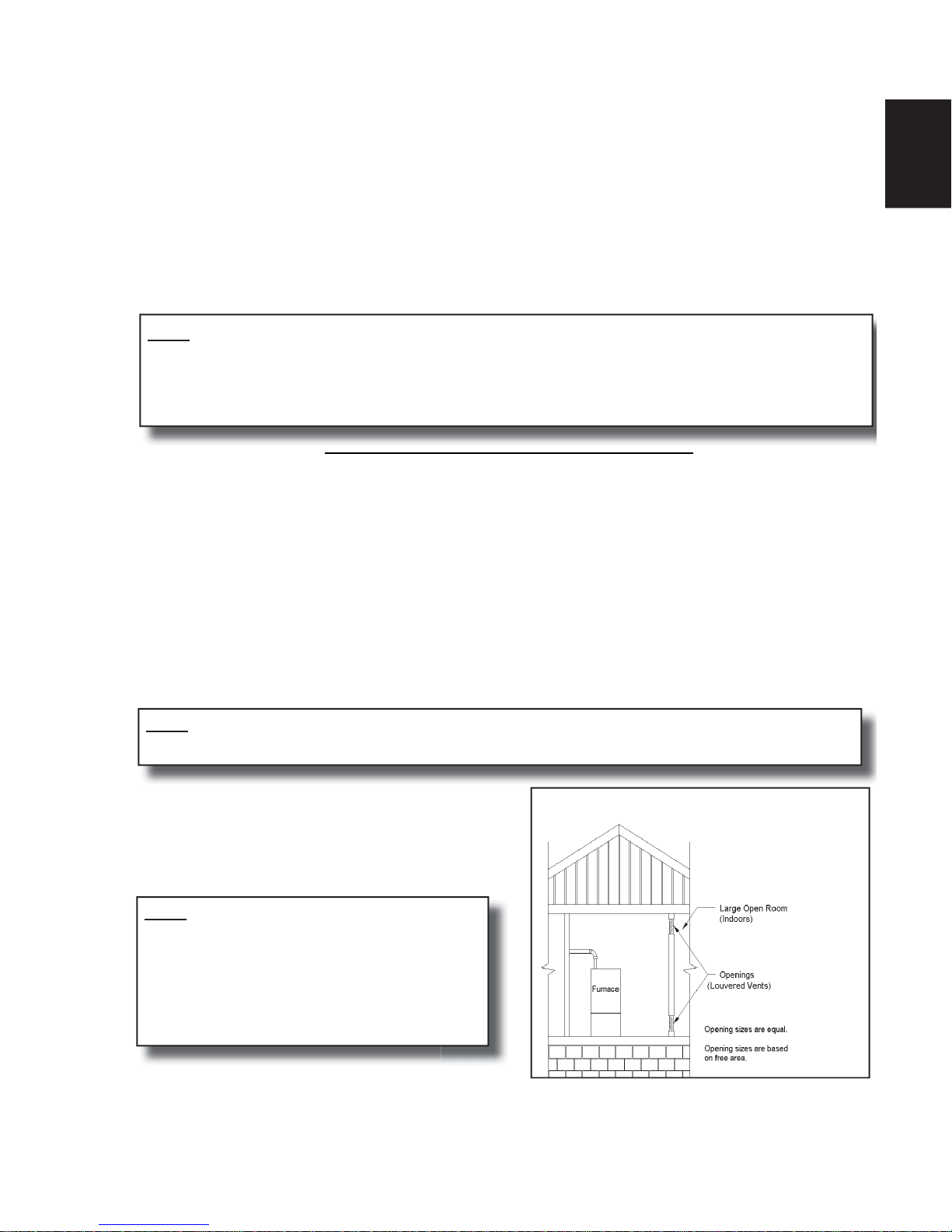
A confi ned space, (any space smaller than the minimums discussed in Case 1), must have two air openings;
one within 12” (305mm) of the ceiling and the other within 12” (305mm) of the fl oor. The air openings must
be sized based on whether the combustion and ventilation air is being taken from indoors or outdoors, the
method outdoor air (if used) is introduced, and taking into account any other fuel burning appliances in the
confi ned space.
If suffi cient indoor combustion and ventilation air is available for the furnace and all other fuel burning
appliances, size each opening on the basis of one square inch (645mm²) of free area per 1000 Btu/hr.
(Figure 4)
NOTE
Be sure to consider all clothes dryers, bathroom fans, range hoods, etc., when making this calculation.
The minimum requirement for these openings is 100
square inches (645mm²), even for the furnace models
under 100,000 Btu/hr.
NOTE
If using grills to cover the two openings, factor in the
free area of the grill. Typically, a sidewall grill will
have a free area approximately 50% of its nominal
size. Consequently, if the required opening is 10" x
10" (254mm x 254mm), it will have to be doubled if
using a sidewall grill with 50% free area.
FIGURE 4 - COMBUSTION/DILUTION AIR FROM
HEATED INSIDE SOURCES (CASE 2)
Page 18
W415-1241 / A / 03.18.15
18
IOM
IOM
8.1.3 CASE 3: FURNACE LOCATED IN A CONFINED SPACE, OUTDOOR AIR
FROM ATTIC OR CRAWL SPACE
H13.2
IMPORTANT:
IF AN EXHAUST FAN, FIREPLACE, CLOTHES DRYER OR ANY SIMILAR DEVICE IS PRESENT IN THE
INDOOR AREA FROM WHICH THE COMBUSTION AND VENTILATION AIR WILL BE DRAWN, NEGATIVE PRESSURE COULD BE A PROBLEM IF NATURAL INFILTRATION FROM THE OUTDOORS DOES
NOT MATCH THE RATE AT WHICH AIR IS EXHAUSTED.
H13.3
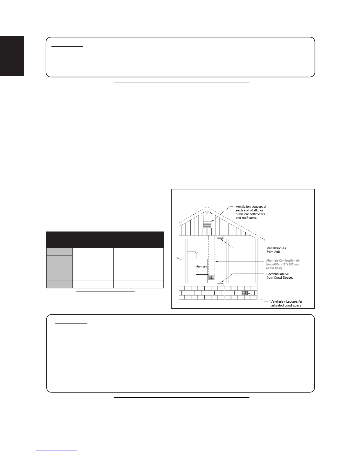
FIGURE 5 - OUTSIDE AIR FOR COMBUSTION, ATTIC OR
CRAWL SPACE (CASE 3)
Alternate Combustion Air
from Attic. (12” / 305 mm
above oor)
In this circumstance, the free area of each of the two combustion and ventilation air openings is based on a
minimum of 1 square inch (645mm²) per 4000 Btu/hr. In this confi guration, one opening can originate from the
fl oor drawing combustion and ventilation air from the ventilated crawl space.
The other opening may communicate freely with the ventilated attic. If using the attic air, ensure that the
opening is ducted from the ceiling high enough to be above the insulation. The attic must be adequately
vented with soffi t vents or gable vents (Figure 5).
As an alternative to creating an opening in the fl oor to draw air from a crawl space, a duct may be dropped from
the attic terminating 12” (305mm) above the fl oor.
The following table shows minimum free areas and round pipe sizes when drawing combustion air vertically
from the attic or crawl space for the furnace
only. If other fuel burning appliances are
present, their combustion air and ventilation
air requirements must be added to those of
the furnace.
IMPORTANT:
IF THE ATTIC HAS AN EXHAUST FAN (POWER VENT), IT MAY CREATE A NEGATIVE
PRESSURE SUFFICIENTLY LARGE ENOUGH TO PREVENT THE ATTIC FROM BEING
AN EFFECTIVE SOURCE OF COMBUSTION AND VENTILATION AIR. POWERED ATTIC
FANS DO NOT CUSTOMARILY RUN DURING THE HEATING SEASON; HOWEVER,
SOME ARE CONTROLLED BY A HUMIDISTAT AS WELL AS A THERMOSTAT, WHICH MAY
ALLOW SOME OPERATION DURING THE HEATING SEASON. THE CHOICES ARE (A)
USE THE DIRECT VENT OPTION; (B) OBTAIN OUTDOOR AIR FROM ELSEWHERE; OR
(C) INTERLOCK THE ATTIC EXHAUST FAN WITH THE FURNACE SUCH THAT THE TWO
CANNOT OPERATE SIMULTANEOUSLY.
TABLE 2 - VERTICAL AIR SUPPLY (CASE 3)
Input Free Area
Round Pipe Size
K/Btu/hr Ea. Opening
40
15 in.² (97cm²) 5 in. (127mm)
60
80 20 in.² (129cm²)
6 in. (152mm)
100 25 in.² (16cm²)
120 30 in.² (194cm²) 7 in. (178mm)
H12.16.5
Page 19
W415-1241 / A / 03.18.15
19
IOM
8.1.4 CASE 4: FURNACE LOCATED IN A CONFINED SPACE, OUTDOOR AIR
DUCTED HORIZONTALLY
8.1.5 CONNECTION TO FURNACE NON-DIRECT VENT
H13.4
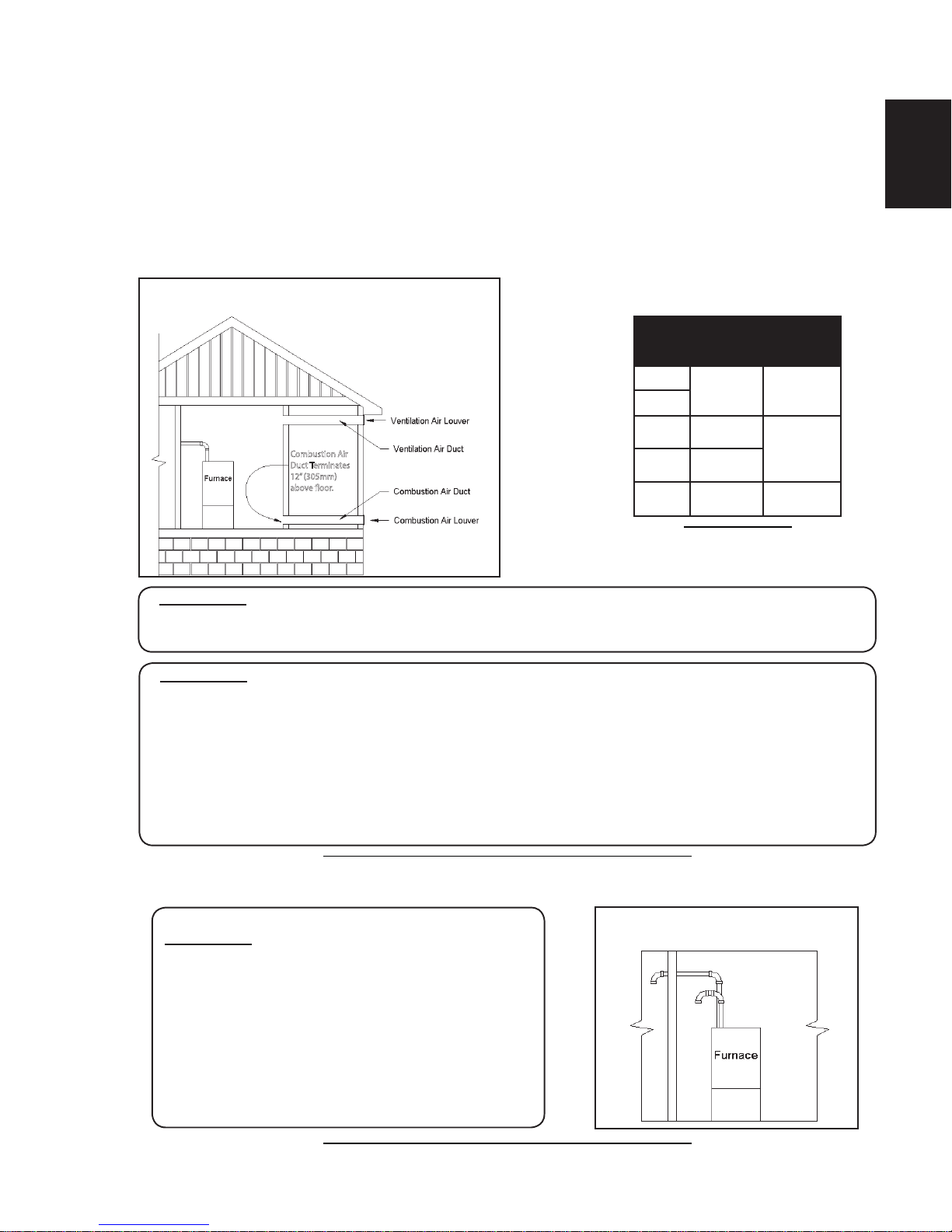
Similar to Case 3, outdoor air for combustion and ventilation may be drawn through horizontal ducting. The
free area for each opening is calculated on the basis of a minimum of 1 square inch (645mm²) per 2000 Btu/hr
input.
The following table shows minimum free areas and round pipe sizes when drawing combustion air horizontally
from the outdoors for the furnace only. If other fuel burning appliances are present, their combustion air and
ventilation air requirements must be added to those of the furnace.
IMPORTANT:
IF GRILLS ARE USED ON THE OUTSIDE WALL, THEY MUST BE SIZED PROPERLY.
MOST SIDEWALL GRILLS HAVE ONLY 50% FREE AREA. IN THE CASE OF A UNIT WITH
100,000 BTU/HR INPUT, WHICH REQUIRES A PAIR OF 8” (203mm) ROUND PIPES TO
OBTAIN SUFFICIENT COMBUSTION AND VENTILATION AIR, THE DUCT COULD BE AN
EQUIVALENT RECTANGULAR DUCT; 8” X 7” (203mm X 178mm) FOR EXAMPLE. BASED
ON 50% FREE AREA FOR THE INLET GRILLS, THE ACTUAL GRILL SIZE WOULD HAVE
TO BE 14” X 8” (356mm X 203mm) OR ITS EQUIVALENT. A TRANSITION MAY BE USED TO
REDUCE TO THE SMALLER DUCT SIZE IF NECESSARY.
IMPORTANT:
THE OUTDOOR GRILLS MUST BE INSTALLED IN A LOCATION WHERE THEY WILL NOT BE
OBSTRUCTED IN ANY MANNER.
Combustion Air
Duct Terminates
12” (305mm)
above oor.
FIGURE 6 - OUTDOOR AIR FOR COMBUSTION,
HORIZONTAL (CASE 4)
H13.5
FIGURE 7 - NON-DIRECT
COMBUSTION AIR INLET
IMPORTANT:
WHEN USING INDOOR AIR OR THE NON-DIRECT
VENT CONFIGURATION, THE COMBUSTION AIR
INLET TO THE FURNACE MUST BE PROTECTED
FROM BLOCKAGE. USE A DOUBLE ELBOW
ARRANGEMENT IF SUPPLYING COMBUSTION AIR
THROUGH THE TOP, OR A DOWNWARD POINTING
SINGLE ELBOW IF SUPPLYING COMBUSTION AIR
THROUGH THE SIDE. (FIGURE 7)
TABLE 3 - HORIZONTAL AIR
SUPPLY (CASE 4)
Input
K/Btu/hr
Free Area
Ea. Opening
Round Pipe
Size
40
30 in
2
(194cm2)
7 in
(178mm)
60
80
40 in
2
(258cm2)
8 in
(203mm)
100
50 in
2
(323cm2)
120
60 in
2
(387cm2)
9 in
(229mm)
H12.9.5
Page 20
W415-1241 / A / 03.18.15
20
IOM
IOM
9.0 VENTING GUIDELINES
FAILURE TO FOLLOW ALL VENTING GUIDELINES MAY RESULT IN ERRATIC FURNACE
OPERATION, FREEZE-UP OF THE EXHAUST AIR PIPING, OR SOOTING OF THE FURNACE.
CAUTION
!
!
NOTE
• Combustion air intake and exhaust termination should be inspected periodically to ensure they are clear of
obstructions. i.e. vegetation, debris, snow, etc.
• Accumulation of snow around the combustion air intake and exhaust termination may have negative
effects on appliance operation and/or performance. Snow accumulation should be considered when
locating combustion air intake and exhaust terminations.
• Venting may be vertical or horizontal.
• Minimum vent length - 15 total equivalent feet (4.6m). (See Venting Table)
• Horizontal piping must slope back towards the furnace at a minimum rate of 1/4" to the foot (18mm per
meter), so that condensate drains towards the furnace.
• Horizontal runs must be supported at least every 3 feet (914mm). Horizontal sections must not dip or sag.
• All vent runs through unconditioned space where freezing might occur should be insulated with 1” (25mm) thick,
medium density, foil-faced Fiberglass insulation. An equivalent “arm-a-fl ex” or “rub-a-tex” may also be used as
long as there is no heat tape applied to the vent pipe. For horizontal runs where water may collect, wrap the vent
pipe with self regulating 3 or 5 watt heat tape. The heat tape must be CSA, UL, or ULC listed and installed per
the manufacturer’s instructions. This includes travel through unconditioned attic space.
• DO NOT COMMON VENT WITH ANY OTHER APPLIANCE.
• If venting vertically, do not vent up a chimney serving another appliance or install in a chase with a metal
or high temperature plastic pipe from another gas or fuel burning appliance unless the required clearances
to combustibles can be maintained between the furnace venting system and other pipes.
It is recommended that an offset is created (2 x 45°s) in the vertical exhaust vent piping to reduce the risk of
fl ooding the exhauster with excessive vent condensate run down.
All exhaust piping must be installed in accordance with CAN/CGA-B149.in Canada; the latest edition of National
Fuel Gas Code, NFPA 54 / ANSI Z223.1 in the United States, as well as in accordance with local codes.
IMPORTANT:
• CLEAN AND DE-BURR ALL PIPE CUTS (INCLUDING UNCUT VENT LENGTHS). THE
SHAVINGS MUST NOT BE ALLOWED TO BLOCK THE EXHAUST, COMBUSTION AIR INLET
OR CONDENSATE DRAIN LINES.
• IF THE PIPE AND FITTINGS ARE TO BE OTHER THAN PVC, USE THE PROPER CLEANER,
PRIMER AND CEMENT FOR THE DISSIMILAR MATERIALS.
• THE EXHAUST VENT MUST BE SUPPORTED APPROPRIATELY PRIOR TO IT BEING
FITTED TO THE EXHAUSTER. UNDER NO CIRCUMSTANCES SHALL THE EXHAUSTER
BEAR ANY WEIGHT OF THE VENTING SYSTEM.
H3.12
READ AND FOLLOW ALL INSTRUCTIONS IN THIS SECTION. FAILURE TO PROPERLY VENT THIS
FURNACE CAN CAUSE CARBON MONOXIDE POISONING OR AN EXPLOSION OR FIRE RESULTING
IN PROPERTY DAMAGE, PERSONAL INJURY OR LOSS OF LIFE.
WARNING
!
!
Page 21
W415-1241 / A / 03.18.15
21
IOM
9.1 VENT TERMINATION
H14.0
Size the combustion air and exhaust piping in accordance
with Table 4. When calculating allowable vent lengths, be
sure to count all termination fi ttings in addition to counting the
concentric vent as a straight pipe.
Take the building orientation and the presence of other
buildings or other nearby structures into consideration
when planning the venting system location. Certain
external structures could create air turbulence around the
vent termination leading to downdrafts and similar venting
problems. In windy and hill locations, roof venting may improve
operations. Maximum venting length is based on 30 mph
(48 km) winds, areas where higher gusts are dominant it is
suggested to shorten the horizontal vent length.
The vent and combustion air intake shall be installed so that
both are located in the same wind pressure zone.
*3"
(76mm)
MIN.
12"
(305mm)
MIN.
INTAKE
EXHAUST
GRADE
*18" (457mm) MIN. FOR COLD
CLIMATES (SUSTAINED 0°F (-18°C)
FOR 24 OR MORE CONSECUTIVE
HOURS
FIGURE 8 - STANDARD (STRAIGHT)
HORIZONTAL VENT DETAIL
H3.13
DO NOT CONNECT FURNACE TO A CHIMNEY OR FLUE SERVING OTHER APPLIANCES OR A
SOLID FUEL BURNING APPLIANCE.
WARNING
!
!
TABLE 4 - DIRECT AND NON-DIRECT VENT LENGTHS
Maximum Allowable Length Of Exhaust Or Intake. Minimum Vent Length 15 ft. (4.6 m) or equivalent.
INPUT
K/Btu/hr
PIPE
SIZE
NUMBER OF 90° ELBOWS
NOTES
0123456
40**
1½ 60* 55 50 45 40 35 30
1. Count concentric vent
fi tting as straight pipe.
2. Use medium or long
sweep elbows where
possible.
3. One 90° elbow is
equivalent to two 45°
elbows.
4. For direct vent, the
listed lengths are
allowed for each vent
(intake and exhaust).
5. For non-direct vent,
the listed lengths are
allowed for exhaust.
The intake should have
a 1½” or 2” snorkel
intake fi tting. (Figure 7)
2 75* 70 65 60 55 50 45
60
1½ 60* 55 50 45 40 35 30
2 75* 70 65 60 55 50 45
3 100* 95 90 85 80 75 70
80
2 50* 45 40 35 30 25 20
3 100* 95 90 85 80 75 70
100
2 50* 45 40 35 30 25 20
3 100* 95 90 85 80 75 70
120 3 100* 95 90 85 80 75 70
H12.4.5
NOTE When 1½” or 3” pipe is used, exit the cabinet with 2” pipe. Reduce
or increase immediately after exiting the cabinet on both intake and exhaust.
* Maximum allowable vent (intake and exhaust) length.
** 40 K units must be vented with 1½” venting if total run length is to be less
than 25 ft. (7.6m).
orizontal vents should pass through the exterior wall. Figure 8 shows a standard horizontal vent detail.
erminate the vent approximately 8” (203mm) or more from the wall.
xterior vent pipe greater than 24” (610mm) should be insulated with 1/2” (13mm) insulation to prevent
oisture from freezing within the pipe and accumulating.
ize the exhaust pipe as specifi ed in
Table 4 - Direct and Non-Direct Vent
engths. This table lists the maximum
llowable length of pipe with respect to
he number of 90° elbows used. For the
urposes of this calculation, one 90°
lbow is equivalent to two 45° elbows.
Avoid locating the terminal in locations
here dripping condensate may cause
problems such as sidewalks, patios,
above planters, near windows where
exhaust gases may cause fogging, etc.
Avoid locating the termination too close
to shrubs and other vegetation. The
condensate may stunt or kill them.
EQUIVALENTS
Short Radius Elbow = 7 ft (2.13m)
Standard Radius Elbow = 5 ft (1.52m)
Long Radius Elbow = 3 ft (0.91m)
45 Degree Elbow = 2.5 ft (0.76m)
Vent lengths that require more than
6-90° elbows, add listed equivalents
for every elbow up to the maximum
allowable vent length.
Page 22
W415-1241 / A / 03.18.15
22
IOM
IOM
9.2 IN CANADA
9.3 IN UNITED STATES
H14.1
18" (457mm) MIN.
ROOF TERMINATION
EXHAUST
FIGURE 10 - VERTICAL VENTING
MOISTURE IN THE FLUE GASES CONDENSES AS IT LEAVES THE TERMINAL. THIS MOISTURE
CAN FREEZE ON EXTERIOR WALLS, ON SOFFITS, AND OTHER NEARBY OBJECTS. SOME
DISCOLORATION IS TO BE EXPECTED; HOWEVER, IMPROPER LOCATION OR INSTALLATION CAN
CAUSE STRUCTURAL OR EXTERIOR FINISH DAMAGE TO THE BUILDING.
CAUTION
!
!
Caulk all cracks, seams or joints within a 6 foot (1.8m) radius of the termination.
Do not terminate under a deck unless there is adequate clearance to prevent damage from the fl ue gases.
A termination may be located at the end of a patio deck. Piping running beneath the deck must be suitably
insulated and suspended in a manner to prevent condensate from collecting and freezing.
Do not locate the terminal on the side of the building facing the prevailing winter winds.
FIGURE 9 - PERISCOPED VENT DETAIL
INTAKE
EXHAUST
GRADE
*3"
(76mm)
MIN.
12"
(305mm)
MIN.
12"
(305mm)
MIN.
*18" (457mm) MIN. FOR COLD
CLIMATES (SUSTAINED 0°F (-18°C)
FOR 24 OR MORE CONSECUTIVE
HOURS
H14.2A
In addition to the general guidelines, in Canada, the vent exhaust shall not terminate:
• Directly above a paved sidewalk or paved driveway which is located between two single-family dwellings
and serves both dwellings;
• Less than 7 feet (2.1m) above a paved sidewalk or paved driveway located on public property;
• Within 6 feet (1.8m) of a mechanical air supply inlet to any building;
• Above a meter/regulator assembly within 3 feet (.91m) horizontally of the center line of the regulator;
• Within 3 feet (.91m) of any service regulator vent outlet;
• Less than 12” (305mm) above grade level or anticipated snow level;
• Within 12” (305mm) of any door, window, or non-mechanical air supply inlet to any building;
• Within 12” (305mm) of the combustion air inlet of any other appliance;
• Underneath a veranda, porch or deck, unless (a) the veranda, porch or deck is fully open on a minimum
of two sides beneath the fl oor, and (b) the distance between the top of the vent termination and the
underside of the veranda, porch or deck is greater than 12” (305mm).
In addition to the general guidelines, in the United States, the vent exhaust shall be installed in accordance
with the following:
• The clearance from the bottom of the terminal to grade shall be 12” (305mm).
• The vent shall not terminate over public walkways or over an area where condensate or vapor could
create a nuisance or hazard.
• The vent terminal shall be installed 4 feet (1.2m) below, 4 feet (1.2m) horizontally from, or 1 foot (305mm)
above any door, window, soffi t, under eave vent or gravity air inlet to the building.
• The vent terminal shall have a minimum horizontal clearance of 4 feet (1.2m) from electric meters, gas
meters, regulators and relief equipment.
Page 23
W415-1241 / A / 03.18.15
23
IOM
9.4 FURNACE VENTING INSTALLATIONS
9.4.1 NON-DIRECT VENT INSTALLATION USING INDOOR COMBUSTION AIR
(ONE PIPE SYSTEM)
9.4.2 DIRECT VENT INSTALLATION USING OUTDOOR COMBUSTION AIR (TWO
PIPE SYSTEM)
9.4.3 COMBUSTION AIR
H14.3
• Locate the vent terminal 3 feet (0.91m) above any forced air inlet located w
ithin 10 feet (3m). A
ny fresh air
or make-up air inlet, such as for a dryer or furnace area is considered a forced air inlet.
The vent terminal should be located no fewer than 3 feet (0.91m) from an inside corner formed by two exterior walls.
Recommended clearance from overhangs is a minimum of 1 foot (0.3m) vertically for each foot horizontally up
to 6 feet (1.8m).
H3.14
READ AND FOLLOW ALL INSTRUCTIONS IN THIS SECTION. FAILURE TO PROPERLY
VENT THIS FURNACE CAN CAUSE CARBON MONOXIDE POISONING OR AN EXPLOSION
OR FIRE RESULTING IN PROPERTY DAMAGE, PERSONAL INJURY OR LOSS OF LIFE.
WARNING
!
!
H14.4
Non-direct vent installations require only a vent pipe. This may be desirable when using outdoor combustion
air is not practical.
• Provisions are not made for routing of combustion air;
• The outdoor environment may contain contaminants undesirable for combustion.
• Install a short piece of intake air pipe with a 90° elbow to prevent objects from entering burner
area, and or objects from blocking combustion air intake.
H14.5
The direct vent confi guration is the preferred installation method. The primary advantages are:
• No special kit or modifi cations are required for direct vent installations
• Dedicated combustion air and vent piping eliminates the need to use already heated air for combustion
purposes;
• The probability of corrosive contaminants being present in the combustion air is greatly reduced;
• The direct vent confi guration is unaffected by any other appliances, exhaust fans, or other devices that
tend to create negative pressure conditions while operating.
• No vents for combustion and ventilation air are required in confi ned spaces.
H14.6
This furnace is certifi ed as a Category IV Type FSP Non-Direct and Direct Vent Furnace. When installed
as a direct vent furnace, all combustion air is supplied from the outdoors via the plastic piping system. All
components are fi eld supplied, except for the 2” PVC connector used to connect the combustion air piping to
the furnace.
The combustion air piping, like the exhaust piping, must be air tight throughout the system. The adapter joining
the combustion air to the furnace is supplied with one gasket.
IMPORTANT:
• IF PLANNING TO USE ABS PIPE, USE AN ALL-PURPOSE CLEANER AND ABS
TO PVC TRANSITION CEMENT. IF PLANNING TO USE CPVC PIPE, USE AN ALLPURPOSE CLEANER, A CLEAR OR PURPLE PRIMER AND ALL-PURPOSE CEMENT
APPROVED FOR THE PURPOSE.
• ADDITIONAL INFORMATION ABOUT CLEANERS, PRIMERS, SOLVENTS AND
CEMENTS MAY BE OBTAINED FROM THEIR MANUFACTURERS.
• IF THE FURNACE IS TO BE INSTALLED IN THE VICINITY OF OTHER FUEL BURNING
APPLIANCES, ADEQUATE COMBUSTION AIR MUST BE AVAILABLE FOR THE NON-
DIRECT VENT APPLIANCES. SEE SECTION 8.1, “DETERMINING COMBUSTION AIR”.
Page 24

W415-1241 / A / 03.18.15
24
IOM
IOM
10.0 TERMINATIONS
10.1 COMBUSTION AIR
10.2 EXHAUST
10.3 CONCENTRIC VENTING KIT
10.4 CONCENTRIC VENT TERMINATION INSTALLATION INSTRUCTIONS
H15.1
HORIZONTAL - The combustion air termination is
made up of a medium or long sweep 90° elbow pointing
downward to prevent rain from readily entering the
combustion air intake piping.
If the required clearance to grade cannot be obtained
with the “straight through” confi guration, the combustion
air intake pipe may be “periscoped” up to 24” (610mm) to
gain extra height (Figure 9)
VERTICAL - The combustion air termination is made up
of a pair of medium or long sweep 90° elbow pointing
downward to prevent rain from entering the combustion
air intake piping.
The combustion air inlet must be located a minimum of
12” (305mm) above grade, and 12” (305mm) below the
exhaust outlet. (Figure 11)
12"
(305mm)
MIN.
3"
(76mm)
MIN.
18"
(457mm)
MIN.
12"
(305mm)
MIN.
ROOF TERMINATION
EXHAUST
FIGURE 11 - STANDARD VERTICAL VENTING
DETAIL
H15.2
HORIZONTAL - The exhaust termination is normally a 45° elbow or a medium or long sweep 90° elbow
pointing within 45° of the downward position, away from the combustion air intake terminal.
If the required clearance to grade cannot be obtained with the “straight through” confi guration, the exhaust pipe
may be “periscoped” up to 24” (610mm) to gain extra height. (Figure 9) In this case, the fl ue gases may be
expelled horizontally. Use the same size pipe as the interior run and count the fi ttings and length as part of the
total vent length.
If winter prevailing wind conditions are variable and likely to occasionally blow fl ue gases back in on the
combustion air intake, the exhaust termination may be raised 18-24” (457mm x 610mm) above the combustion
air intake terminal to take advantage of the natural buoyancy of the fl ue gases to help prevent re-circulation of
the exhaust. (Figure 9)
VERTICAL - No termination fi tting is required if venting vertically through a roof.
The end of the exhaust pipe must be 12” (305mm) higher than the entrance of
the combustion air intake terminal. (Figure 11)
The exhaust pipe extending through the roof must extend a minimum of 18”
(457mm) above any obstruction within an 18” (457mm) horizontal distance.
Insulate all venting that extends 24” (610mm) or more to the outside.
NOTE: Always clean out
exhauster collar after installation. Vent pipe shavings
from initial installation can
cause blockage in the exhauster collar drain.
H15.3
Concentric venting terminal kits may be used for this series furnace. They provide a means of obtaining
combustion air and exhausting products of combustion utilizing a single penetration through the exterior wall.
This can be useful when there is limited wall space available. Kits are available in:
• 2" Reference kit #196005 (use with model inputs of 30, 40, 60 and 80) Wolf Steel kit W370-0019
• 3" Reference kit #196006 (use with model inputs of 80, 100 and 120) Wolf Steel kit W370-0020
• Terminals are made by IPEX Inc. See installation instructions for details.
If venting with 1½” vent material, and a concentric vent kit is necessary, a increase coupling may be used to
connect to the 2” concentric venting kit. Read the instructions supplied with the kit for additional installation
instructions and details. Straight vertical runs should have offset to push condensate against vent walls.
H15.4
Follow the concentric vent termination manufacturer instructions for installation of the concentric vent
termination kit. These instructions can be found by contacting the furnace manufacture. Furnace
manufacturer contact information is found on the front cover of this installation manual and operating
instructions.
10.5 LOCATION
void locating the terminals where the fl ue gas could become stagnant and allow recirculation into the
combustion air intake.
Page 25

W415-1241 / A / 03.18.15
25
IOM
10.6 MULTIPLE VENTING
H15.6
COMMON VENTING IS PROHIBITED!!
If two of these furnaces are to be installed in close proximity, the combustion air intake and exhaust
terminations may be installed as shown in Figures 12 and 13.
IMPORTANT:
WHEN INSTALLING MULTIPLE FURNACES IN CLOSE PROXIMITY, EACH REQUIRES
DEDICATED COMBUSTION AIR AND EXHAUST VENTING.
If more than two furnaces are being installed in close proximity, each additional combustion air intake and
exhaust termination set shall not terminate less than 12 in (305mm) apart. Note: Canadian installations of
120000 Btu/hr require 3 ft (915mm).
FIGURE 13 - MULTIPLE VENTING (STANDARD
VERTICAL)
12" (305mm)
MIN. ABOVE
SNOW LEVEL
30" (762mm) MAX.
12" (305mm)
MIN.
3"
(76mm)
MIN.
TO BE REDUCED
FROM 3" PVC TO
2" PVC BELOW THE
COMBUSTION AIR
INTAKE 2" PVC
TWO FURNACES VENTING
THROUGH ROOF
3"
3"
(75mm)
MIN.
INTAKE
8"
(203mm)
MIN.
2"
(51mm)
MIN.
12" (305mm) MIN.
12" (305mm) MIN.
12"
(305mm)
MIN.
GRADE
EXHAUST
FIGURE 12 - MULTIPLE VENTING (STANDARD
HORIZONTAL)
H15.5
void locating the terminal in locations where dripping condensate may cause problems such as sidewalks,
patios, above planters, near windows where exhaust gases may cause fogging, icing, etc.
void locating the termination too close to shrubs and other vegetation. The condensate may stunt or kill them.
Caulk all cracks, seams or joints within a 6 foot (1.8m) radius of the termination.
Do not terminate under a deck unless there is adequate clearance to prevent damage from the fl ue gases.
termination may be located at the end of a patio deck. Piping running beneath the deck must be suitably
insulated and suspended in a manner to prevent condensate from collecting and freezing.
hen locating vent terminations, consideration must be given to prevailing winds, location, and other
conditions which may cause recirculation of the combustion products of adjacent vents.
IMPROPER LOCATION OR INSTALLATION CAN RESULT IN STRUCTURAL DAMAGE TO
THE BUILDING, DAMAGE TO THE EXTERIOR FINISH OF THE BUILDING, OR MAY ALLOW
RECIRCULATION OR FREEZING OF THE FLUE GASES ONTO OR INTO THE COMBUSTION
AIR INTAKE.
MOISTURE IN THE FLUE GASES CONDENSES AS IT LEAVES THE TERMINALS. THIS
MOISTURE CAN FREEZE ON EXTERIOR WALLS, SOFFITS, AND OTHER NEARBY
OBJECTS. SOME DISCOLORATION IS TO BE EXPECTED.
CAUTION
!
!
he vent terminal should be located no fewer than 3 feet (.9m) from an inside corner formed by two exterior walls.
Recommended clearance for overhangs is a minimum of 1 foot (.3m) vertically for each foot horizontally up to
6 feet (1.8m).
ny adjacent painted surfaces should be in good condition; no cracks, peeling paint, etc. If wooden surfaces that
may be periodically exposed to fl ue gases are present, consider treating with a sealer.
H3.15
RECIRCULATION OF FLUE GASES MAY OCCUR CAUSING THE INTAKE PIPE TO
FREEZE SHUT DURING COLD WEATHER OPERATION IF THE VENTING SYSTEM IS NOT
INSTALLED PER THESE GUIDELINES.
WARNING
!
!
Page 26

W415-1241 / A / 03.18.15
26
IOM
IOM
FIGURE 14A - DIRECT VENT TERMINAL CLEARANCES
Page 27

W415-1241 / A / 03.18.15
27
IOM
FIGURE 14B - NON-DIRECT VENT TERMINAL CLEARANCES
Page 28

W415-1241 / A / 03.18.15
28
IOM
IOM
11.0 ROUTING OPTIONS
11.1 EXHAUSTER ROTATION INSTRUCTIONS & PRESSURE SWITCH MOUNTING
H16.0.1A
This furnace can be installed in any of the four positions. Figures 16 to 20 on the following pages shows the
four installation positions. The installer must consider the following services: gas pipe, electrical power, drain
trap, intake and exhaust vents. Also consider the air conditioning connections and drain, access to
fi lter(s) and access to furnace and a/c for repair. Drains and traps of furnaces installed in spaces
subjected to freezing temperature must also be protected against freezing.
The combustion air inlet fi tting is a 2” PVC Socket to Pipe Thread adapter. Choose the intake
location and remove the appropriate plastic cap. Install the adapter to the exterior panel using the
gasket (on the outside of the panel and the locknut on the inside of the panel). Failure to apply
gasket on cabinet exterior voids the warranty.
H16.1.2A
1. Disconnect exhauster wire connection.
2. Remove the 3 exhauster screws.
3. Remove pressure switch assembly (switches) and front manifold cover pressure sensing hose.
4. Remove exhauster.
5. Reverse the bands on the rubber drain coupling so the screws are accessible if necessary. (Do not
reverse the drain coupling.) Confi rm that directional arrow on drain coupling points away from exhauster.
6. Remove the appropriate plastic cap on the side panel. Install cap on vent opening not in use.
7. Reinstall the exhauster and the pressure switch assembly in the correct orientation with the (3) exhauster
screws removed in step 2. DO NOT USE POWER TOOL. Reinstall the pressure switches so that they
are above the heat exchanger drain, to eliminate the chance of condensate draining into the pressure
switch sensing hose causing erratic furnace operation. See Figures 16-20 for reference.
8. Rotate the drain coupling so the drain holes are angled downward 15° and tighten coupling band to
exhauster.
9. Complete the venting as installation requires.
Always secure or support the vent and intake to the fl oor joists or rafters to avoid sagging and possible fatigue
of venting materials. This ensures proper drainage and prevents spilling the products of combustion into the
building.
The blower compartment should be completely isolated from the burner compartment, and in tight rooms with
other combustion devices, be completely isolated from the room. Ensure that the combustion door gasket is in
good condition.
IMPORTANT:
KEEP PRESSURE SWITCH HOSES ABOVE HEAT EXCHANGER DRAIN, AND CUT TO
APPROPRIATE LENGTH TO PREVENT ANY SAGS OR TRAPS FORMING IN THE HOSES.
ORIENTATION
ROTATE
EXHAUSTER
SEE FIGURES
16 - 20 FOR
RECOMMENDED
MOUNTING
FURNACE FLUE
Down Left Y
Down Right Y
Up Left Y
Up Right Y
Up Vertical N
Horz.Left Vertical Y
Horz. Left Vertical N
Horz.Right Vertical Y
Horz.Right Right N
TABLE 5 - EXHAUSTER ORIENTATION
NOTE
DO NOT
USE POWER
TOOL
Page 29

W415-1241 / A / 03.18.15
29
IOM
11.2 CONDENSATE DRAINS
11.3 PREPARATIONS FOR VENT AND DRAINING OPTION
H16.2.2C
The furnace may condense as much as 4-1/2 pounds of water per hour (approximately 2 imperial quarts, 2-1/2
U.S. quarts or 2-1/4 liters). It is necessary to make provisions for draining the condensate away. The furnace is
supplied with a drain trap assembly. See Figures 16-20 for possible locations of the drain trap.
Affi x the condensate trap assembly to the interior of the side panel in the blower compartment for upfl ow
positions; the interior of the side panel in the burner compartment for downfl ow positions. For horizontal
positions affi x the condensate trap assembly to the exterior side panels. See Figures 16-20.
Three plastic drain hose clamps are provided in the parts bag. The large ones are used for securing the drain
hose to the front manifold cover drain outlet, and securing the drain hose to the 5/8” barbed fi tting on the
condensate trap assembly. The small one is used to secure the drain hose to the 1/2” barbed fi tting on the
condensate trap assembly.
The drain coupling on the exhauster will work better if the drain holes are pointed down about 15 degrees. The
drain hose supplied with the furnace is long enough to reach either side panel; however, it must be cut to fi t each
application. This is to prevent kinking in the drain lines.
NOTE: It is recommended that pliers be used to fi rmly clamp the plastic hose clamps.
H16.3.2A
1. Determine the most suitable vent and drain options for installation. See Figures 16-20 for reference, and
refer to Exhauster Rotation Instructions section if necessary.
2. Remove the 3-1/2” plastic exhaust vent cap (if required), and cover vent hole not in use. Install rubber
grommet (in parts bag) for 2” vent pipe. Connect vent pipe (field supplied). If using 1-1/2” or 3” vent, make
transition as close as possible to the unit and on a vertical section.
3. Connect 2” air intake pipe (field supplied). The exhaust vent must be supported appropriately prior to
it being fitted to the exhauster. Under no circumstances shall the exhauster bear any weight of the
venting system.
4. Remove the plastic air inlet cap and connect the 2” PVC air intake connector with the rubber gasket on the
outside of the unit using the 2” lock nut (in parts bag).
5. Remove the two plastic caps attached to the blower division, and the one attached to the side panel if
applicable.
6. Affix the condensate trap assembly to the interior of the side panel in the blower compartment for upflow
positions using the two screws provided in parts bag. For horizontal positions affix the condensate trap
assembly to the exterior side panels.
7. Make sure combustion compartment is fully sealed.
NOTE
• Condensate drain tubing must be cut to
appropriate length and slopping towards
condensate trap, ensuring that drain hoses
do not create traps prior to the condensate
trap assembly.
• Condensate trap must be primed with
water prior to initial furnace start up.
• Any increase of venting diameter must
be done on the vertical sections NOT
horizontal sections.
NOTE
Barbed fi ttings must be fully inserted into
condensate trap, seated to barb fl ange.
BARB FLANGE
Page 30

W415-1241 / A / 03.18.15
30
IOM
IOM
IMPORTANT:
CONNECT ½” TEE FITTING (FIELD SUPPLIED)
TO THE OUTLET OF THE CONDENSATE TRAP.
FIGURE 15
FIGURE 16 - UPFLOW VENT AND DRAINING OPTION
LEFT VENT INSTALLATION TOP VENT INSTALLATION
IMPORTANT:
• PRIME CONDENSATE TRAP WITH WATER AND CUT DRAIN HOSES TO PROPER LENGTH.
• CUT PRESSURE SWITCH TUBING TO PROPER LENGTH.
NOTE
Trap can be
installed on
the left or
right side of
the unit.
Only left
side install
pictured.
H3.16
THERE MUST NOT BE ANY OPENINGS BETWEEN THE BLOWER DIVISION PANEL AND
THE COMBUSTION COMPARTMENT. THE BLOWER COMPARTMENT IS UNDER GREATER
SUCTION THEN THE COMBUSTION COMPARTMENT AND CAN PULL COMBUSTION
AIR FROM THE BURNERS AND CAUSE INCOMPLETE COMBUSTION AND ERRATIC
FURNACE OPERATION.
WARNING
!
!
Page 31

W415-1241 / A / 03.18.15
31
IOM
RIGHT VENT INSTALLATION
NOTE
Upfl ow Vent Right - condensate
trap must be installed on left side.
IMPORTANT:
• PRIME CONDENSATE TRAP WITH
WATER AND CUT DRAIN HOSES TO
PROPER LENGTH.
• CUT PRESSURE SWITCH TUBING
TO PROPER LENGTH.
FIGURE 18 - HORIZONTAL LEFT VENT AND DRAINING OPTION
LEFT VENT INSTALLATION TOP VENT INSTALLATION
IMPORTANT:
• PRIME CONDENSATE TRAP WITH WATER AND CUT DRAIN HOSES TO PROPER LENGTH.
• CUT PRESSURE SWTICH TUBING TO PROPER LENGTH.
FIGURE 17 - UPFLOW VENT AND DRAINING OPTION CONTINUED
Page 32

W415-1241 / A / 03.18.15
32
IOM
IOM
FIGURE 19 - HORIZONTAL RIGHT VENT AND DRAINING OPTION
RIGHT VENT INSTALLATION
IMPORTANT:
• PRIME CONDENSATE TRAP WITH WATER AND CUT DRAIN HOSES TO PROPER LENGTH.
• CUT PRESSURE SWITCH TUBING TO PROPER LENGTH.
TOP VENT INSTALLATION
FIGURE 20 - DOWNFLOW VENT AND DRAINING OPTION
LEFT VENT INSTALLATION
RIGHT VENT INSTALLATION
IMPORTANT:
• PRIME CONDENSATE TRAP WITH WATER AND CUT DRAIN HOSES TO PROPER LENGTH.
• CUT PRESSURE SWITCH TUBING TO PROPER LENGTH.
NOTE
Trap can be
installed on
the left or
right side of
the unit.
Only left
side install
pictured.
Page 33

W415-1241 / A / 03.18.15
33
IOM
THE TWO INLETS TO THE DRAIN TRAP ARE FOR VENT PIPE AND CONDENSATE
COLLECTION. THE VENT PIPE INLET IS SMALLER THAN THE CONDENSATE
COLLECTION INLET. ENSURE THAT THE DRAIN HOSES ARE PROPERLY CUT TO THE
REQUIRED LENGTH CONNECTED AND SECURED.
CAUTION
!
!
11.4 DRAIN HOSE INSTALLATION
11.4.1 DRAIN PIPING
H16.4
1. Connect one end of the 5/8” tubing (in parts bag) to the most direct drain outlet on the front manifold cover,
and the other end to the larger elbow on the condensate trap assembly. Cut excess tubing if necessary
and hold in place with the supplied plastic hose clamps (in parts bag).
2. Connect one end of the 1/2” tubing, using the reducing coupling (in parts bag), to the lower drain outlet
on the exhauster coupling, and the other end to the smaller elbow on the condensate trap assembly. Cut
excess tubing if necessary.
NOTE
All condensate drain tubing must slope towards the condensate trap, ensuring that the drain
hoses do not create traps or kinks in the hose prior to the condensate trap assembly.
H16.4.1
Condensate from the outlet of the drain trap assembly must be conveyed to a fl oor drain, sump pit, or, if these
are unavailable, to a condensate pump. If using a condensate pump, be sure that it is approved for furnace
condensate.
DO NOT DRAIN THE CONDENSATE OUTDOORS. DO NOT RUN THE CONDENSATE LINE
THROUGH AREAS WHERE FREEZING MIGHT OCCUR. FREEZING OF CONDENSATE CAN
RESULT IN ERRATIC FURNACE OPERATION AND IN PROPERTY DAMAGE.
CAUTION
!
!
A typical confi guration would be to cement the side branch of a 1/2” CPVC tee to the drain trap assembly
outlet, with the end branches oriented vertically. (Figure 15)
A 1” (25mm) piece of 1/2” CPVC pipe cemented to the upper end branch will serve as a vent, which will
prevent the creation of a vapor lock, and serve as an overfl ow in the event that the drain line becomes
blocked. A similarly sized piece of pipe cemented to the lower end branch will permit connection to the
condensate outlet with 5/8” ID / 7/8” OD fl exible tubing, or the condensate may be piped entirely in CPVC to
the fl oor drain/sump/condensate pump.
IMPORTANT:
IF AN AIR CONDITIONING EVAPORATOR COIL DRAIN IS TO SHARE THE FURNACE DRAIN
LINE, IT SHOULD BE CONNECTED WITH A TEE FITTING DOWNSTREAM FROM THE
TRAP. DO NOT CONNECT THE EVAPORATOR COIL CONDENSATE DRAIN UPSTREAM OF
THE FURNACE DRAIN TRAP ASSEMBLY.
NOTE
It is recommended that the condensate drain assembly not be cemented to the condensate trap
outlet, if removal of the condensate trap is required in the future. Use a piece of the provided 1/2”
drain hose if removal of the condensate trap is anticipated.
Page 34

W415-1241 / A / 03.18.15
34
IOM
IOM
11.4.2 PRIMING CONDENSATE TRAP
11.5 ALTERNATE CONDENSATE DRAIN PIPING INSTALLATION USING 1/2” PVC
OR 3/4” CPVC
H16.4.2
IMPORTANT:
THE CONDENSATE DRAIN TRAP ASSEMBLY SHOULD BE FULL OF WATER (PRIMED)
BEFORE STARTING THE FURNACE. TO FILL THE CONDENSATE DRAIN TRAP ASSEMBLY,
TEMPORARILY REMOVE THE VENT DRAIN HOSE FROM THE EXHAUSTER ASSEMBLY
ELBOW/DRAIN FITTING, AND POUR APPROXIMATELY ONE CUP OF WATER DOWN THE
HOSE. WATER WILL BEGIN RUNNING OUT THE CONDENSATE DRAIN TRAP OUTLET
WHEN IT IS FULL. REFASTEN THE VENT DRAIN HOSE TO THE EXHAUSTER ASSEMBLY
ELBOW/DRAIN FITTING.
THE CONDENSATE DRAINAGE CONFIGURATION REQUIRES A VENT. IT TAKES LESS
THAN A ONE INCH RISE ANYWHERE ALONG THE HORIZONTAL ROUTE OF THE DRAIN
TUBE TO CREATE A VAPOR LOCK, WHICH WILL PREVENT CONDENSATE FROM
DRAINING AWAY FREELY, AND RESULT IN ERRATIC FURNACE OPERATION.
1. The supplied parts bag includes a length of 1/2” and 5/8” rubber hose and the condensate trap. Install the
condensate trap according to instructions included in this manual.
FIGURE 21 FIGURE 22
FIGURE 23 FIGURE 24
2. If installing with 1/2” PVC, use the 1/2” hose. If installing with 3/4” CPVC, use the 5/8” hose. Slide the
appropriate hose over the condensate trap outlet and cut it fl ush with the end of the outlet. The remaining
rubber should be fl ush with the end of the outlet on the condensate trap. The remaining hose is suffi cient
length to accommodate all furnace orientations.
3. A 1/2” PVC coupling or bushing will fi t snug over the 1/2” rubber hose. A 3/4” CPVC coupling or bushing will
fi t snug over the 5/8” rubber hose. This method ensures a water tight seal and also allows the condensate
trap to be easily removed for service.
Page 35

W415-1241 / A / 03.18.15
35
IOM
11.6 CONDENSATE NEUTRALIZERS
H16.5.1A
4. If extra security is desired, it is recommended to secure a strip of strapping around the drain. Utilize the
existing condensate trap screws to secure the strapping.
FIGURE 25 FIGURE 26
H16.6
Some local codes may require the use of a condensate neutralizer. If the furnace condensate is to be routed to
a septic system, it may be advisable to use a condensate neutralizer.
When condensate neutralizers are used, it is advisable to install it with an overfl ow bypass tube.
Page 36

W415-1241 / A / 03.18.15
36
IOM
IOM
12.0 GAS SUPPLY AND PIPING
12.1 GAS SUPPLY
12.2 GAS PIPING
H3.18
THIS FURNACE IS FACTORY EQUIPPED TO BURN NATURAL GAS ONLY.
CONVERSION TO LP GAS REQUIRES A NATURAL GAS TO LP CONVERSION KIT (W370-0018).
FAILURE TO USE THE PROPER CONVERSION KIT CAN CAUSE FIRE, EXPLOSION, CARBON
MONOXIDE POISONING, PROPERTY DAMAGE, PERSONAL INJURY OR LOSS OF LIFE.
WARNING
!
!
H17.1
IMPORTANT:
• CONVERSION OF THIS FURNACE REQUIRES SPECIALIZED EQUIPMENT.
CONVERSION MUST BE COMPLETED BY A TRAINED AND QUALIFIED INSTALLER,
SERVICE AGENCY OR GAS SUPPLIER.
• CONNECT THIS FURNACE ONLY TO GAS SUPPLIED BY A COMMERCIAL UTILITY
OR SUPPLIER. PRIVATE GAS WELLS DO NOT GENERALLY PROVIDE GAS WITH
CONSISTENT, UNIFORM AND PREDICTABLE HEATING VALUES AND DENSITIES.
MANY NON-COMMERCIAL WELLS CONTAIN IMPURITIES SUCH AS SULPHUR, WHICH
MAY DAMAGE THE FURNACE. THIS FURNACE CANNOT OPERATE PROPERLY OR
SAFELY USING FUELS OUTSIDE NORMAL COMMERCIAL STANDARDS.
In Canada, the gas piping should be installed in accordance with CAN/CSA-B149.1 and 2, and in accordance
with any local codes.
In the United States, the gas piping should be installed in accordance with (NFGC) NFPA 54 / ANSI Z223.1
and any local codes.
If local codes allow the use of a fl exible gas appliance connector, always use a new listed connector. Do not
use a connector, which has previously serviced another gas appliance.
IMPORTANT:
To maintain a good seal in the burner area,
the gas piping through the side panel into
the furnace must be 1/2” Schedule 40 black
iron pipe. The pipe passes through a special
rubber grommet that is custom manufactured
to seal tightly around the gas pipe. (Figure 27)
The gas piping may enter the furnace from either
side. Once the routing of the gas pipe is determined,
select and remove the plastic cap if necessary and
install on other panel, and install the grommet within
the hole.
NOTE
We recommend a union between the gas valve and the side panel to allow easy removal of the burner for
service purposes.
FIGURE 27 - FURNACE GAS PIPE CONNECTIONS
(NOTE RUBBER GROMMET)
Page 37

W415-1241 / A / 03.18.15
37
IOM
12.3 GAS INLET PRESSURE
12.4 LEAK TESTING
12.5 PURGING GAS LINES
H17.2B
IMPORTANT:
ALWAYS USE A BACKUP
WRENCH TO PREVENT TWISTING
OF THE GAS VALVE. ANY
STRAINS ON THE GAS VALVE
CAN AFFECT POSITIONING OF
THE ORIFICES RELATIVE TO THE
BURNERS. THIS COULD RESULT
IN FAULTY BURNER OPERATION.
Install a manual gas shut-off valve and dirt pocket as close to the furnace as possible. Some local codes call
for the manual gas shut-off valve to be located between 4 feet (1.2m) to 5 feet (1.5m) above fl oor level to
prevent tampering by small children. Ensure that the valve is readily accessible.
IMPORTANT:
ENSURE
THAT THE
GAS VALVE
IS NOT
SUBJECTED
TO HIGH
PRESSURES.
H3.19
DISCONNECT THE MANUAL SHUT-OFF VALVE AND GAS VALVE DURING ANY
PRESSURE TESTING THAT EXCEEDS 1/2 P.S.I.G. (3.45 KPA).
WARNING
!
!
H17.3.2
The natural gas inlet supply pressure should be 5” to 7” w.c. (7” w.c. recommended). The LP gas inlet supply
pressure should be 11” to 13” w.c. (12” w.c. recommended). These pressures must be maintained while all other
gas fi red appliances are operating at maximum conditions.
IMPORTANT:
DO NOT EXCEED 13” W.C. INLET PRESSURE WITH EITHER FUEL.
The gas valve has two adjustable internal regulator for controlling burner manifold pressure. Burner manifold
high fi re and low fi re pressures are listed on the furnace rating plate.
H17.4
All new gas piping installations should be pressure tested as specifi ed by CAN/CSA-B149.1 & 2, or NFPA 54
ANSI Z223.1 or ANSI/NFPA 58, “Standard for the Storage and Handling of Liquefi ed Petroleum Gases.”
Gas piping that has not been pressure tested, from the manual shut-off valve to the furnace gas valve for
example, should be leak tested using an electronic combustible gas detector, a commercially prepared leak
detector, or other locally approved method.
H3.20
NEVER USE A MATCH, TAPER, CIGARETTE LIGHTER, FLAME OR ANY OTHER IGNITION
SOURCE TO CHECK FOR LEAKS IN A GAS LINE.
FAILURE TO ADHERE TO THIS WARNING CAN CAUSE A FIRE OR EXPLOSION
RESULTING IN PROPERTY DAMAGE, PERSONAL INJURY, OR LOSS OF LIFE.
WARNING
!
!
Page 38

W415-1241 / A / 03.18.15
38
IOM
IOM
13.0 CONVERSIONS
13.1 HIGH ALTITUDE CONVERSION
H18.1B
In Canada, this funace does not need to be converted for high altitude (2000-4500ft), when the fuel source
is natural gas. It has been certifi ed to operate at high altitude as manufactured. If the fuel source is liquid
propane, refer to High Altitude Specifi cations table for appropriate derate above 2000ft based on a 4%
reduction of input capacity for every 1000ft above sea level.
In the United States, this furnace does not need to be converted for high altitude from (2000-5400ft), when
the fuel source is natural gas. It has been certifi ed to operate at high altitude as manufactured up to 5400ft
only. Beyond 5400ft the modifi cations are based on a 4% reduction of input capacity for every 1000ft above
sea level. If the fuel source is liquid propane, refer to High Altitude Specifi cations table for appropriate derate
above 2000ft based on a 4% reduction of input capacity for every 1000ft above sea level. Consult with local
fuel suppliers or authorities to determine local regulations or customs.
Input
K/Btu/hr
ALTITUDE
ORIFICE SIZE (DMS)
NATURAL LP GAS
40/60/80
100/120
0-2000 (0-610 m)
45
55
2000-3000 (610-914 m) 56
3000-4000 (914-1219 m) 57
4000-5000 (1219-1524 m) 58
5000-5400 (1524-1646 m)
59
5400-6000 (1646-1829 m) 51 60
6000-7000 (1829-2134 m) 52 61
7000-8000 (2134-2438 m) 53 62
8000-9000 (2438-2743 m) 54 63
9000-10000 (2743-3048 m) 55 65
TABLE 6 - HIGH ALTITUDE SPECIFICATIONS
Gas input ratings are certifi ed for elevations to 5400 ft. (1646 m) on natural gas. For elevations above 5400 ft. (1646 m) on natural gas, or
LP fuel source above 2000 ft. (610 m), follow orifi ce derate chart above.
H12.8.1A
Input
K/Btu/hr
ALTITUDE
ORIFICE SIZE (DMS)
NATURAL LP GAS
30
0-2000 (0-610 m)
50
57
2000-3000 (610-914 m)
58
3000-4000 (914-1219 m)
59
4000-5000 (1219-1524 m)
60
5000-5400 (1524-1646 m)
61
5400-6000 (1646-1829 m)
56
62
6000-7000 (1829-2134 m)
57 63
7000-8000 (2134-2438 m)
58 64
8000-9000 (2438-2743 m)
59 65
9000-10000 (2743-3048 m)
60 67
H18.2A
This series furnace is manufactured as a natural gas appliance that may be converted to LP gas through use of
the Conversion Kit part number W370-0018. This kit contains the conversion kit instructions, orifi ces needed
for all models, the regulator spring for the gas valve, and a label to affi x adjacent to the appliance rating plate to
alert subsequent service technicians of the conversion. The parts removed for this conversion must remain
with the furnace for any future conversion back to natural gas.
H18.3
Refer to Conversion NG to LP Kit (W370-0018) for complete instruction.
WHITE-RODGERS 36G54 TWO STAGE GAS VALVE
1. Turn off the gas and electrical supply to the furnace.
2. Back inlet pressure test screw (inlet pressure boss, see FIGURE 31) counterclockwise out one turn
maximum, with a 3/32” Allen wrench. Attach a hose and calibrated U-tube or digital manometer to the inlet
pressure boss. Hose should overlap boss 3/8”. The manometer must have a scale range of at least 0” to
15” of water column.
3. Turn ON the gas and electrical supply and operate the furnace and all other gas consuming appliances on
the same gas supply line. Using a leak detection solution, check for leaks around the gas valve/manifold
connection and the burner orifi ces. Repair any leaks before continuing.
4. Measure furnace gas inlet pressure with burners fi ring. Inlet pressure must be within the range specifi ed
on the furnace rating plate. 5-7” w.c. (Natural Gas) or 11-13” w.c. (LP).
If the inlet pressure differs from the rating plate, make the necessary adjustments to pressure regulator,
gas piping size, etc. and/or consult with local gas utility.
13.2 NATURAL TO LP GAS
13.3 CONVERSION STEPS
13.4 CHECKING THE INLET GAS PRESSURE
Page 39

W415-1241 / A / 03.18.15
39
IOM
FIGURE 32 - VALVE PRESSURE CHECK KIT
FIGURE 31 - WHITE RODGERS 36G54 GAS VALVE
H18.4.2
5. Turn off gas and electrical supply to furnace, remove the manometer hose from the inlet pressure tap
boss, and tighten the inlet pressure tap screw using the 3/32” Allen wrench. (Clockwise, 7 in-lb minimum).
6. Turn on the gas supply and electrical power to the furnace.
7. Using a leak detection solution, check for leaks at pressure boss screw. Bubbles forming indicate a leak.
SHUT OFF GAS AND FIX ALL LEAKS IMMEDIATELY!
8. Turn gas back on and test inlet pressure boss with leak detector.
9. If working on a natural gas system, contact the gas utility. They may insist on any service regulator
adjustments being made by their own staff.
If problems were encountered with obtaining enough pressure, fi rst examine the gas piping system to ensure
that it is correctly sized. Pipe sizing is specifi ed in CAN/CSA-B-149.1 & 2, and in NFPA 54 / ANSI Z223.1. Be
sure to check for restrictions, partially closed valves, etc.
In some circumstances, high inlet pressure can be remedied with the use of an in line appliance regulator. If
an in line appliance regulator is used, ensure that it has the capacity to adequately handle the gas volume
required by the furnace and any other appliances receiving gas from the header serving the furnace.
When the installation is completed to the
“S
tart-up & Setup” stage, test the gas mani
f
old pressure by following
these steps:
WHITE-RODGERS 36G54 TWO STAGE GAS VALVE
1. Turn off the gas and electrical supply before proceeding.
2. Back outlet pressure test screw (outlet pressure boss, see Fig.31) counterclockwise out one turn
maximum, with a 3/32” Allen wrench. Attach a hose and calibrated U-tube or digital manometer to the
outlet pressure boss. Hose should overlap boss 3/8”. The manometer must have a scale range of at least
0” to 15” of water column.
3. Turn on the gas supply and electrical power to the furnace and energize main solenoid by connecting R to
W1 on the integrated control board. Do not energize the HI solenoid.
4. Remove regulator adjustment cover screw from the low outlet pressure regulator adjust tower (Fig.31) and
turn the plastic regulator adjustment screw clockwise to increase manifold pressure or counterclockwise
to reduce manifold pressure. Always adjust regulator according to original equipment manufacturer’s
specifi cations listed on the appliance rating plate. Replace regulator cover screw.
5. Energize main solenoid as well as the HI terminal by connecting R/W1 and W1/W2 on the integrated
furnace control. Remove regulator cover screw from the high outlet pressure regulator adjust tower
(Fig.31) and turn the plastic regulator adjustment screw clockwise to increase manifold pressure or
13.5 SETTING THE MANIFOLD GAS PRESSURE
Page 40

W415-1241 / A / 03.18.15
40
IOM
IOM
counterclockwise to reduce manifold pressure. Manifold pressure should be set to 1.4” w.c low fi re, 3.5”
w.c high fi re for natural gas, 4.0” w.c low fi re, 10.0” w.c. high fi re for LP gas. Always adjust regulator
according to original equipment manufacturer’s specifi cations listed on the appliance rating plate.
When the correct pressure has been established, securely replace the regulator cover screw.
6. Turn off the gas and electrical supply to the furnace.
H3.21
ALL REGULATOR ADJUSTMENTS MUST BE DONE BY A TRAINED, QUALIFIED
TECHNICIAN. IMPROPER MODIFICATIONS OR ADJUSTMENTS CAN RESULT IN FIRE OR
EXPLOSION CAUSING PROPERTY DAMAGE, SEVERE PERSONAL INJURY OR LOSS OF
LIFE.
WARNING
!
!
H18.5.4
7. Remove the manometer hose from the outlet pressure tap boss, and tighten the outlet pressure tap screw
using the 3/32” Allen wrench. (Clockwise, 7 in-lb minimum).
8. Turn on the gas supply and electrical power to the furnace.
9. Turn on system power and energize valve.
10. Using a leak detection solution or soap suds, check for leaks at pressure boss screw. Bubbles forming
indicate a leak. SHUT OFF GAS AND FIX ALL LEAKS IMMEDIATELY!
FIGURE 30 - MANOMETER MEASURING GAS MANIFOLD PRESSURE
H18.6.2
IMPORTANT:
NEVER ADJUST THE INPUT
OF THE FURNACE TO
EXCEED THE INPUT SHOWN
ON THE RATING PLATE.
Input =
Heating Value of Gas x 3600
Time in Sec. for 1 cu. ft.
where:
• input is expressed in Btu/hr
• heating value of the gas is expressed in Btu/ft
3
• and time is the number of seconds required for
the test dial to indicate 1 cubic foot.
If using a gas meter with SI (metric) units:
• 1 cubic foot = 0.0283 cubic meters
• 1 cubic meter = 35.315 cubic feet
• 0.01 cubic meter = 0.3531 cubic feet
• 0.5 cubic meter = 1.766 cubic feet
The natural gas supply pressure should be a maximum of 7” w.c. and minimum of 5” w.c. The burner manifold
pressure is factory set to 3.5” w.c. High Fire, 1.4” w.c. Low Fire. The input rating of the furnace is based on
1000 Btu/ft.³ gas with a specifi c gravity of 0.6.
Since heating values for the gas vary geographically, the actual furnace input and output will vary accordingly.
For example, natural gas with a 900 Btu/ft.³ heating value will reduce the input to 90% of the rated input.
Natural gas with a 1100 Btu/ft.³ heating value will increase the input to approximately 110% of the rated input.
This is not usually a problem; however, adjustments to compensate for this can be made by minor adjustments
to the burner manifold pressure or by changing the burner orifi ce size. Contact the fuel supplier for specifi c
heating content values.
A
ny adjustments to the burner manifold pressure should be carried out with the use of a manometer or
calibrated Magnehelic® gauge. Do not adjust the gas valve pressure regulator more than ±0.3” w.c. Refer to
Figure 30.
13.6 CHECKING FURNACE INPUT
Page 41

W415-1241 / A / 03.18.15
41
IOM
14.0 ELECTRICAL SPECIFICATIONS
14.1 ELECTRICAL WIRING AND CONNECTIONS
Before proceeding with the electrical connections, ensure that the available electrical supply is compatible with
the voltage, frequency and phase listed on the appliance rating plate.
All furnaces are rated 120 VAC, 60 Hz, 1 Ø. The amperage rating is 15 amps or less.
Each furnace requires a dedicated 15 amp over-current device, either a 15 amp circuit breaker or a 15 amp
Type D time delay fuse. It is permissible to connect furnace accessories such as humidifi er transformers,
condensate pumps and electronic air cleaners. If adding accessory equipment to the furnace circuit, ensure
that the combined amperages listed on the appliance rating plates does not exceed the rating of the overcurrent device.
FIGURE 35 - ELECTRICAL CONNECTIONS /
MOLEX CONNECTOR
WHITE
BLACK
GREEN
H19.1
In Canada, all electrical work must be in accordance with the latest
edition of CSA-C22.1, Canadian Electrical Code Part 1, and any
applicable local code.
In the United States, all electrical work must be in accordance with
the latest edition of the National Electrical Code, ANSI / NFPA 70.
A
lthough a suitably located circuit may serve as a service switch, a
separate service switch is recommended. A separate service switch
is necessary if the circuit breaker is in a location where accessing it
would require getting close to the furnace, or if the furnace is located
between the main electrical panel and the entry to the furnace room.
The furnace switch (service switch) should be clearly labeled,
and installed in a location where it is not likely to be mistaken as
being a light switch or similar control.
H3.22
SHUT OFF ELECTRICAL POWER AT THE FUSE BOX OR SERVICE PANEL BEFORE
MAKING ANY ELECTRICAL CONNECTIONS. FAILURE TO DO SO CAN CAUSE
ELECTRICAL SHOCK RESULTING IN PERSONAL INJURY OR LOSS OF LIFE.
• THE FURNACE CABINET MUST HAVE AN UNINTERRUPTED GROUND.
• A GROUND WIRE IS PROVIDED IN THE ELECTRICAL JUNCTION BOX.
• DO NOT USE GAS PIPING AS A GROUND.
FAILING TO GROUND THE FURNACE PROPERLY CAN RESULT IN ELECTRIC SHOCK
RESULTING IN PERSONAL INJURY OR DEATH.
WARNING
!
!
Page 42

W415-1241 / A / 03.18.15
42
IOM
IOM
14.2 FURNACE CONNECTION
5A FUSE
24 VAC MOLEX
ICM
INTERFACE
THERMOSTAT
TERMINALS
FAULT CODE
BUTTON
RED STATUS
LED
HEAT STAGING
JUMPER P5
120 VAC NEUTRAL
CONNECTIONS
120 VAC
MOLEX
POWER
HUMIDIFIER
ELECTRONIC
AIR CLEANER
PARK
TERMINALS
FIGURE 36 - INTEGRATED FURNACE IGNITION CONTROL
H19.2
The furnace is shipped fully wired except for the connections to the house wiring. The furnace power
connections are made in a junction box inside the blower compartment. The junction box contains a BLACK
wire to be connected with L1 (hot), a WHITE wire to be connected with L2 (Neutral), and a GREEN wire to be
connected to the ground.
If the junction box must be moved from it’s original location to the other side of the unit.
1. Remove the appropriate plastic cap from the desired left or right side panel, and place it on the panel not
being serviced.
2. Fasten the junction box to the selected panel.
3. Secure power line connection into junction box, following above reference.
4. Use only ground screws for junction enclosure.
NOTE
Use good quality wire nuts such as Marrette®
connectors, Ideal® wire nuts, etc.
IMPORTANT:
USE COPPER CONDUCTORS ONLY.
H3.23
THIS FURNACE IS EQUIPPED WITH A BLOWER DOOR SAFETY SWITCH. DO NOT
DISABLE THIS SWITCH. FAILURE TO FOLLOW THIS WARNING CAN RESULT IN
ELECTRICAL SHOCK, PERSONAL INJURY, OR LOSS OF LIFE.
WARNING
!
!
Page 43

W415-1241 / A / 03.18.15
43
IOM
15.0 LOW VOLTAGE WIRING
15.1 SINGLE STAGE THERMOSTAT
FIGURE 38 - JUMPER P5
15.2 TWO STAGE THERMOSTAT
15.3 THERMOSTAT LOCATION
H53.1
The thermostat and control wiring should be a minimum of 18 AWG copper. Excessive lengths of wire may
result in enough voltage drop to impair the proper functioning of the furnace. For thermostat wires in excess of
25 feet (7.6m), use 16 AWG; 50 feet (15.2m), use 14 AWG.
H53.4
Th
e automatic heat staging option allows a single stage thermostat to be used w
ith
a two stage furnace. The
control provides a movable jumper (P5) to select between 5 minute and *10 minute automatic staging. Automatic staging time begins when the blower is energized after the heat blower delay period. If the jumper is in
the 5 minute position, the control will automatically start high heat after 5 minutes of continuous low heat operation. If the jumper is in the *10 minute position, the control will automatically start high heat after 10 minutes
of continuous low heat operation. Once high heat is started from automatic staging, the demand for high heat
remains until the heat call is satisfi ed. * Factory Setting
H53.3
When connecting a two stage thermostat, the jumper (P5) must
be in the “NONE” position. The control runs high heat from the
thermostat W2 demand.
H53.2
The thermostat should be located approximately 5 feet (1524mm) above the fl oor, on an inside wall where there
is good natural air circulation, and where the thermostat will be exposed to average room temperatures. Avoid
locations where the thermostat will be exposed to cold drafts, heat from nearby lamps or appliances, exposure to
sunlight, heat from inside wall stacks, etc.
H24.15
THERMOSTAT IFC
R G W Y
Y
1
Y
2
W R G C
FIGURE 33 - THERMOSTAT CONNECTION DIAGRAM
Page 44

W415-1241 / A / 03.18.15
44
IOM
IOM
16.0 OPTIONAL ACCESSORIES (FIELD SUPPLIED/
INSTALLED)
16.1 ELECTRONIC AIR CLEANER
16.2 POWER HUMIDIFIER
16.3 EMERGENCY HEAT MODE
H20.1.1
The integrated furnace control has provisions to supply power and control an electronic air cleaner rated at
120VAC, 1.0 amp max. 120 volt power will be available at these terminals whenever the
circulating fan is operating in the heating or cooling fan modes.
H20.2
NOTE
All HUM and EAC terminals are 120V. Do not directly connect 24V equipment to these terminals.
The integrated furnace control has provisions to supply power and control a line voltage humidifi er or the
primary of a 120 / 24 volt humidifi er step down transformer, rated at 120VAC, 1.0 amp max.
H20.3.2A
If the ECM 2.3 / EON blower motor fails and a replacement is not available immediately, you can temporarily
replace the blower motor with a conventional fractional horsepower PSC blower motor. Connect the neutral
wire to a neutral (NEUTRAL) connection terminal on the furnace control board, and the hot (LINE) leg to
the EAC terminal. The EAC terminal is powered during any heating or cooling demand, and the blower will
operate until a new ECM motor can be obtained.
Page 45

W415-1241 / A / 03.18.15
45
IOM
17.0 INITIAL STARTUP PROCEDURES
17.1 TO START THE FURNACE
17.2 TO SHUT DOWN THE FURNACE
H21.0A
This furnace is equipped with a HSI (Hot Surface Ignition) device. Each time that the room thermostat calls for
heat, the HSI lights the main burners directly. See the lighting instructions on the furnace.
When the gas supply is initially connected to the furnace, the gas piping may be full of air. In order to purge this
air, it is recommended that the ground union be loosened until the odor of gas is detected. When gas is detected,
immediately retighten the union and check for leaks. Allow fi ve minutes for any gas to dissipate before continu-
ing with the start-up procedure. Be sure proper ventilation is available to dilute and carry away any vented gas.
During initial start-up, it is not unusual for odor to come out of any room register. To ensure proper ventilation, it
is recommended to open windows and doors, before initial fi ring.
The furnace has a negative pressure switch that is a safety during a call for heat. The induced draft blower must
pull a negative pressure on the heat exchanger to close the negative pressure switch. The induce draft blower
must maintain at least the negative pressure switch set point for the furnace to operate. If the induced draft
blower fails to close or maintain the closing of the negative pressure switch, a “no heat call” would result.
NOTE
It is required/mandatory that the drain trap assembly be primed before the initial startup. Refer to the
instructions on how to prime the condensate trap on the drain piping section in this manual. A dry trap will
allow fl ue gases to fl ow through the recovery coil drain, which will prevent the condensate from draining
from the recovery coil. If enough condensate accumulates in the recovery coil, the recovery coil pressure
switch will sense this condition and break its electrical contacts, and extinguish combustion. If this takes
place, the induced blower will stop after a brief post-purge cycle, the condensate will drain out and fi ll the
trap. If the thermostat is still calling for heat, the ignition sequence will start again after a 5 minute wait.
H21.1
1. Shut off the electrical power to the furnace and set the room thermostat to its lowest setting.
2. Remove the burner compartment access door.
IMPORTANT:
ENSURE THAT THE MANUAL GAS VALVE SWITCH HAS BEEN IN THE “OFF” POSITION
FOR AT LEAST 5 MINUTES. DO NOT ATTEMPT TO MANUALLY LIGHT THE MAIN
BURNERS.
3. Turn the gas valve switch to the “ON” position.
4. Replace the burner compartment access door.
5. Turn on furnace appliance shut off valve.
6. Restore electrical power to the furnace.
7. Set the room thermostat to a point above room temperature to light the furnace.
8. After the burners are lit, set the room thermostat to the desired temperature.
H21.2
1. Set the room thermostat to below set point.
2. Remove the burner compartment access door.
3. Turn the gas valve switch to the “OFF” position.
4. The furnace appliance shut-off valve may be closed if desired.
5. Power to the furnace must remain on for the air conditioner to work.
Page 46

W415-1241 / A / 03.18.15
46
IOM
IOM
H3.24
SHOULD OVERHEATING OCCUR OR THE GAS BURNERS FAIL TO SHUT OFF, CLOSE THE
MANUAL GAS VALVE FOR THE FURNACE BEFORE SHUTTING OFF THE ELECTRICAL
POWER TO THE FURNACE. FAILURE TO DO SO CAN CAUSE AN EXPLOSION OR FIRE
RESULTING IN PROPERTY DAMAGE, PERSONAL INJURY OR LOSS OF LIFE.
BEFORE RESTARTING THE FURNACE, CHECK ALL PLASTIC VENTS AND WIRES FOR
DAMAGE.
WARNING
!
!
17.3 SEQUENCE OF OPERATION
H21.3.2
1. Room temperature drops causing the room thermostat call for fi rst stage heat by connecting “W1” to “R”.
The control verifi es the limit switch is closed and both low and high pressure switches are open. The
control energizes the exhauster motor on high speed and waits for the low pressure switch to close. The
exhauster remains on high speed and begins a 15 second pre-purge period. The high pressure switch is
ignored. If the low pressure switch does not close within 60 seconds, the control will fl ash “2” on the Red
Status LED, and de-energize the exhauster for 60 minutes.
2. When the 15 second pre-purge time has elapsed, the control energizes the HSI output for a 5 second
warm-up period (10 seconds on retries). The control energizes the low main gas valve. 4 seconds after the
gas is energized, the control de-energizes the HSI output and leaves the gas energized another 1 second
for fl ame proving. If fl ame is present at the end of trial for ignition time, the control leaves the gas valve
energized, exhauster on high speed, and begins heat blower on delay. The control always ignites on high
exhauster/low gas and ignores second stage call for heat until low fi re is established for 15 seconds.
3. Blower on delay time begins when the gas valve is energized. The control provides the ECM
(Electronically Commutated Motor) low heat speed signal when fl ame is proven, and starts a 30 second
blower delay before full capacity blower level.
4. When there is a demand for 2nd stage heat from thermostat W2 or automatic staging, the control changes
the exhauster from low to high speed. When high pressure switch closes, the control changes indoor
blower speed from Low heat to High heat and energizes high gas output. If the high pressure switch is
open the Green LED will fl ash. If the high pressure switch is closed the Green LED will be on. High gas
valve drops out while High pressure switch is open because it is directly in series with the high pressure
switch.
5. When the thermostat W2 call ends and W1 remains (two stage thermostat), the control de-energizes the
high gas output and immediately changes exhauster speed from high to low. With the thermostat heating
contacts open (single stage thermostat), the fl ames extinguish immediately and the exhauster blower
stops after a 5 second post purge time.
6. Blower off delay is handled by the ECM (Electronically Commutated Motor). The control de-energizes the
ECM heat signal when the gas valve de-energizes, and starts a programmed delay period.
IN THE EVENT OF FLAME FAILURE:
If fl ame is lost, the control de-energizes the gas valve within 2 seconds, switches the exhauster motor to
high speed (if not already on high), and begins timing the inter-purge delay. The indoor blower motor will be
energized and/or remain energized on heat speed for the programmed delay off time. When the inter-purge
delay is over, the control will re-cycle up to 5 fl ame losses (4 re-cycles) within a single call for heat before
going into lockout. The control fl ashes “8” on the Red LED if lockout is due to too many fl ame dropouts (1 hour
lockout).
17.4 PROGRAMMABLE THERMOSTAT (OPTION)
H21.4
This furnace has an optional programmable two stage Napoleon® Elite Thermostat. For instruction on how
to operate and program this unit, please refer to the manual and installation instructions provided with the
Napoleon® Elite Thermostat Kit.
Page 47

W415-1241 / A / 03.18.15
47
IOM
18.0 AIR FLOW
18.1 TEMPERATURE RISE CHECK
H22.0
For proper furnace operation, air fl ow over the heat exchanger is of utmost importance. Insuffi cient airfl ow
accelerates metal fatigue and possible failure in the heat exchanger, as well as decrease effi ciency. Excessive
airfl ow promotes accelerated corrosion of the heat exchanger.
IMPORTANT:
DO NOT BYPASS THIS STEP OF THE
START UP PROCEDURES.
TABLE 1 - RANGE OF TEMPERATURE RISE
Furnace Models Temperature Rise
ALL
High Fire (HF) 35 - 65°F (20 - 36°C)
Low Fire (LF) 25 - 55°F (14 - 31°C)
H12.15.3
EON: ESP 0.1ʺ to 1.0ʺ / X13: ESP 1.0"
INPUT
A/C EON
EON/CFM
Y1 / Y2
X13
TAP #
X13
CFM
TONNAGE JUMPER
NPV040T2B
NSX040T2B
HIGH BLACK NA / 940 5 940
MED-HIGH BLUE NA / 750 4 750
MED-LOW YELLOW NA / 560 3 560
LOW RED NA *2 N/A
NPV060T3B
NSX060T3B
HIGH BLACK 675 / 1125 5 1125
MED-HIGH BLUE 564 / 940 4 940
MED-LOW YELLOW NA / 750 3 750
LOW RED NA / 560 *2 560
NPV080T3B
NSX080T3B
HIGH BLACK 675 / 1125 5 1125
MED-HIGH BLUE 564 / 940 4 940
MED-LOW YELLOW NA / 750 3 750
LOW RED NA / 560 *2 560
NPV080T4B
NSX080T4B
HIGH BLACK 900 / 1500 5 1500
MED-HIGH BLUE 675 / 1125 4 1125
MED-LOW YELLOW 564 / 940 3 750
LOW RED NA / 750 *2 700
N
PV1
00T5B
NSX100T5B
HIGH BLACK 1050 / 1750 5 1750
MED-HIGH BLUE 540 / 1400 4 1400
MED-LOW YELLOW 630 / 1050 3 1050
LOW RED NA / 750 *2 700
NPV120T5B
NSX120T5B
HIGH BLACK 1050 / 1750 5 1750
MED-HIGH BLUE 840 / 1400 4 1400
MED-LOW YELLOW 630 / 1050 3 1050
LOW RED NA / 700 *2 700
* TAP #2 IS CONTINUOUS FAN
TABLE 10 - AIR FLOW
H12.1.7A
Air fl ow based on approx. 375 cfm/ton. Moving the ADJUST jumper
from the NORM position to the (+) or (-) position ill increase or
decrease the CFM by 15%.
H22.1.2
When the duct system is complete and the air fi lter or fi lters are in place, determine if the airfl ow is correct for both
low and high fi re input rates.
1. Insert a duct thermometer in the supply air duct. The thermometer should be placed as close as practical
to the furnace, but out of the “line of sight” of the heat exchanger (this prevents false readings owing to
radiant heat). Ensure that the thermometer location is within the duct air stream. Avoid locations such as
the inside radius of an elbow, etc.
2. Insert a duct thermometer in the return air duct as close to the furnace as practical. Ensure that the
thermometer location will be unaffected by humidifi er bypass ducts, etc. Choose a location well within the
main air stream.
3. Operate the furnace long enough to obtain steady state conditions at both input rates (High Fire and Low Fire).
4. When the two thermometers have stabilized, usually within 5-8 minutes, compare the two readings.
Subtract the return air temperature from the supply air temperature. The difference is the temperature rise,
also called ∆T.
5. Compare the measured ∆T to the temperature rise range shown on the rating plate.
Unless stated differently on the rating
plate, the temperature rise should
normally range between 35° to
65°F (20° to 36°C) High Fire, 25° to
55°F (14° to 31°C) Low Fire. When
adjusting the temperature rise, the
ideal temperature is approximately
mid-range.
If the measured ∆T is above the
approved temperature range,
there is too little air fl ow. It must
be increased by selecting the
appropriate “HEAT” jumper
setting, removing restrictions in
the ductwork, or adding supply or
return ductwork.
If the measured ∆T is too low, there
is too much air fl ow.
Page 48

W415-1241 / A / 03.18.15
48
IOM
IOM
18.2 CALCULATING AIR FLOW
18.3 ADJUSTING BLOWER SPEEDS ON MODELS EQUIPPED WITH ECM 2.3 / EON
BLOWER MOTORS
H22.2.2A
CFM =
Output
1.085 x
∆T
where:
• CFM is airfl ow in cubic feet per minute;
• ∆T is the temperature rise; and
• Output is the furnace output capacity
from the rating plate
.
There are circumstances where it may be desirable to know the air fl ow delivery through the duct system,
such as when estimating the amount of air fl ow available for
air conditioning. This can be done by direct measurement with
electronic or sloped manometers and velometers, or by counting
the number of times the Amber CFM LED on the control board
fl ashes when equipped with ECM 2.3 / EON motor. Each fl ash
signifi es 100 CFM; count the fl ashes and multiply by 100 to
determine the actual CFM delivered (for example: 10 fl ashes x
100 = 1000 CFM), or use the formula in the next column.
H3.77
DISCONNECT THE ELECTRICAL SUPPLY TO THE FURNACE BEFORE ATTEMPTING TO
CHANGE THE BLOWER SPEED. FAILURE TO DO SO COULD RESULT IN ELECTRICAL
SHOCK RESULTING IN PERSONAL INJURY OR LOSS OF LIFE.
WARNING
!
!
H22.6.1A
his unit is factory set to run at the middle of the heating temperature rise range
s listed on the rating plate. The cooling speed is set to the maximum airfl ow
esignated in the model number.
hree sets of 4 position movable jumpers are provided for Heat, Cool, and Adjust
aps for a variable speed motor. These tap jumpers apply signals to the ECM
motor without other interaction with the control board.
If the blower speeds require adjustment, follow these steps:
1. Remove the blower compartment door.
. Locate the 4 position movable HEAT jumper to adjust heat speed.
NOTE:
Temperature rise should
always be re-checked
whenever blower speed
is changed.
3. Remove the jumper from position A and place it on the
corresponding letter B, C, or D as required. Refer to TABLE
11 - HEATING SPEEDS.
4. To adjust the cooling airfl ow ECM 2.3/EON, remove
the COOL jumper from position A, and place it on the
corresponding letter B, C, or D. Refer to Table 10A and 10B.
Moving the ADJUST jumper from the NORM to the (+) or (-)
position will cause the airfl ow to be increased or lowered by 15%.
The TEST position on the ADJUST tap is not used.
TABLE 11 - HEATING SPEEDS ECM 2.3/EON
ALL MODELS ECM ESP 0.1” to 1.0” w.c.
HEAT
Jumper
ADJUST
Jumper
Low-Fire ▲T
Range 25-55°F
(14-31°C)
High-Fire ▲T
Range 35-65°F
(20-36°C)
A NORM 40°F (22°C) 50°F (28°C)
B NORM 35°F (20°C) 45°F (25°C)
C NORM 45°F (25°C) 55°F (31°C)
D NORM 50°F (28°C) 60°F (33°C)
Note: Moving the ADJUST jumper from the NORM position to the (+) or (-) position will increase or lower the
temperature rise by 15%
H12.7.2A
5A FUSE
24 VAC MOLEX
ICM
INTERFACE
THERMOSTAT
TERMINALS
FAULT CODE
BUTTON
RED STATUS
LED
HEAT STAGING
JUMPER P5
120 VAC NEUTRAL
CONNECTIONS
120 VAC
MOLEX
POWER
HUMIDIFIER
ELECTRONIC
AIR CLEANER
PARK
TERMINALS
FIGURE 36 - INTEGRATED FURNACE IGNITION CONTROL
FIGURE 39
Page 49

W415-1241 / A / 03.18.15
49
IOM
18.4 DEHUMIDIFICATION - ECM 2.3 / EON
18.5 SETTING BLOWER “ON” AND “OFF” TIMINGS - ECM 2.3 / EON MODELS
ONLY
18.6 CONTINUOUS FAN OPERATION
H22.4A
For situations where humidity control is a problem, a dehumidifi cation feature has been built into the variable
speed motor. At the start of each cooling cycle, the variable speed motor will run at 82% of the rated airfl ow for
7.5 minutes. After 7.5 minutes has elapsed, the motor will increase to 100% of the rated airfl ow.
There are three jumper wires in front of the thermostat input terminal block that are used in different
applications. These jumper wires may be cut or clipped when the option is not desired.
• The JW38 jumper not clipped, connects Y1 to Y2 so that the ECM motor only recognizes one input, when
using a single stage thermostat. If you are connecting a single stage A/C unit, input can be on either the
Y or Y2 terminal. If you are connecting a two stage A/C unit, the JW38 jumper must be clipped (1st stage
cool Y1, 2nd stage cool Y2).
• The JW39 jumper not clipped, connects O to R for using a heat pump in the non-heat pump mode (cooling
only). If the JW39 jumper is clipped, the heat pump will run in heat pump mode.
• The JW40 jumper not clipped, connects DEHUM to R for dehumidifi cation active all the time. With the
JW40 jumper clipped, the thermostat,or humidstat controls dehumidifi cation.
H22.5
Blower on/off delays are handled by ECM motor programming. The control de-energizes the ECM heat signal
when the gas valve de-energizes. Features of this ECM variable speed motor are that it will deliver a constant
airfl ow within a wide range of external static pressures, and also includes:
Soft Start: This ECM variable speed motor will slowly ramp up to the required operating speed. This feature in
the heating cycle allows the heat exchanger to reach operating temperature before the set heat speed, which
minimizes noise and increases comfort.
Soft Stop: At the end of the heating or cooling cycle, the ECM variable speed motor will slowly ramp down.
This feature allows for increased energy effi ciency, and reduced noise levels.
H22.3.2A
When the thermostat continuous fan (G) switch is
on without a call for heat or cooling, the indoor fan is
immediately energized up to 50% of the cooling speed.
The fan remains energized as long as the call for fan
remains without a call for heat or cooling. This feature
allows continuous circulation of air between calls for
heating or cooling.
If a call for heat (W) occurs during continuous fan, the
blower will remain energized, the call for heat overides
the call for fan.
If a call for cool (Y) occurs simultaneously with the call
for fan (G), the call for cool overrides the call for fan.
See Air Flow Data table.
Page 50

W415-1241 / A / 03.18.15
50
IOM
IOM
19.0 MAINTENANCE AND TROUBLESHOOTING
19.1 AIR FILTER
19.2 LUBRICATION
H3.25
DISCONNECT THE ELECTRICAL POWER SUPPLY TO THE FURNACE BEFORE ATTEMPTING
ANY MAINTENANCE. FAILURE TO DO SO CAN CAUSE ELECTRICAL SHOCK RESULTING IN
PERSONAL INJURY OR LOSS OF LIFE.
WARNING
!
!
LABEL ALL WIRES PRIOR TO DISCONNECTION WHEN SERVICING CONTROLS. WIRING
ERRORS CAN CAUSE IMPROPER AND DANGEROUS OPERATION.
ALWAYS VERIFY PROPER OPERATION AFTER SERVICING.
CAUTION
!
!
H23.1
The air fi lter should be inspected frequently and cleaned or replaced as necessary. We recommend a monthly
inspection at fi rst, perhaps coinciding with the arrival of the monthly fuel bill as a reminder. The frequency may
be increased or decreased depending on experience and conditions.
Dirty fi lters result in higher than normal operating temperatures, and lower effi ciency.
Some paper media high effi ciency fi lters, sometimes identifi ed as HEPA fi lters can do an effective and
excellent fi ltration of the air; however, some models may also cause a large pressure drop across the fi lter. The
contractor should assess the capabilities of the duct system to deliver suffi cient air fl ow if this type of fi lter is
considered.
RECOMMENDED: Electronic air cleaners using electrostatic precipitation to remove dust are an excellent fi ltration
device when used in conjunction with a pre-fi lter. A 16”
x 25” (406mm x 635mm) model is an ideal fi t with this
furnace in the case of a side mounted return air inlet. The
integrated furnace control is supplied with an electrical
terminal for use with electronic air cleaners.
NOTE
If two return air inlets are used, both must be equipped
with fi lters.
DO NOT OPERATE THE FURNACE FOR PROLONGED PERIODS OF TIME WITHOUT AN
AIR FILTER.
A PORTION OF THE DUST ENTRAINED IN THE AIR MAY LODGE IN THE SUPPLY AIR
DUCTWORK AND REGISTERS. ANY RECIRCULATED DUST PARTICLES WILL BE HEATED
AND CHARRED BY CONTACT WITH THE FURNACE HEAT EXCHANGER. THIS RESIDUE
WILL SOIL CEILINGS, WALLS, DRAPERY, CARPETS, AND OTHER HOUSEHOLD ARTICLES.
CAUTION
!
!
H23.2.2
Both the exhauster motor and circulating fan motor are sealed bearing type motors. Neither requires routine
lubrication.
IMPORTANT:
THE MOTOR BEARINGS WERE PRE-LUBRICATED BY THE MOTOR MANUFACTURER. DO NOT
ATTEMPT TO LUBRICATE THEM. EXCESS LUBRICATION WILL VOID THE WARRANTY, SHORTEN
THE SERVICE LIFE OF THE MOTORS, AND WILL ATTRACT THE BUILDUP OF DUST AND DIRT.
Page 51

W415-1241 / A / 03.18.15
51
IOM
19.3 TROUBLESHOOTING FLOWCHART
H23.3.2
$SSO\3RZHU7R)XUQDFH
7KHUPRVWDW&DOOV)RU+HDW
$LU3URYLQJ6ZLWFKHV
3URYHG2SHQ/LPLW
&LUFXLW&ORVHG
:DLW)RU$LU3URYLQJ6ZLWFK
WR2SHQ)ODVK
:DLW)RU/LPLW&LUFXLW
WR&ORVHDQGRU5HVHW
RI)ODPH5ROORXW
)ODVK
&RPEXVWLRQ$LU%ORZHU2Q
$LU3URYLQJ6ZLWFK3URYHG
&ORVHG:LWKLQ6HFRQGV"
&RPEXVWLRQ$LU%ORZHU2II
)ODVK
0LQXWH:DLW3HULRG
3UHSXUJH6HFRQGV
+6,(QHUJL]HG6HFRQGV
6HFRQGVRQ5HWULHV
/RZ0DLQ9DOYH2SHQV
+6,'H(QHUJL]HG
0DLQ%XUQHU/LJKWV$QG,V6HQVHG
'XULQJ7ULDO)RU,JQLWLRQ"
/RZ0DLQ9DOYH&ORVHV
)DLOHG7ULDOV)RU,JQLWLRQ
/HVV7KDQ)RXU'XULQJ
7KLV,JQLWLRQ6HTXHQFH"
/RZ+HDW&LUFXODWLQJ$LU)DQ2Q
$IWHU3URJUDPPHG'HOD\
)ODPH6HQVH/RVW"
7KHUPRVWDW&DOO)RU+HDW(QGV
/RZ0DLQ9DOYH&ORVHV
&RPEXVWLRQ$LU%ORZHU2II$IWHU3RV
W
3XUJH6HFRQGV
&LUFXODWLQJ$LU)DQ2II$IWHU
3URJUDPPHG'HOD\
:DLW)RU1H[W&DOO)RU+HDW
/RZ0DLQ9DOYH&ORVHV
)ODPH6HQFH/RVW0RUH7KDQ)RX
U
7LPHV,Q7KLV&DOO)RU+HDW"
&RPEXVWLRQ$LU%ORZHU
2II$IWHU3RVW3XUJH
&LUFXODWLQJ$LU)DQ2II
$IWHU3URJUDPPHG
'HOD\
+RXU/RFNRXW5HVHW
'HOD\)ODVK
&DOO)RU+LJK+HDW
$LU3URYLQJ6ZLWFK
3URYHG&ORVHG:LWKLQ
6HFRQGV
)LYH0LQXWH:DLW)RU
5HWU\
+LJK6WDJH0DLQ9DOYH
2SHQV&LUFXODWLQJ$LU
)DQ7R+LJK+HDW6SHHG
+LJK+HDW&DOO(QGV/RZ
+HDW'HPDQG5HPDLQV
+LJK6WDJH0DLQ9DOYH
$QG&DOO)RU+LJK+HDW
&LUFXODWLQJ$LU)DQ'H
(QHUJL]HG
6HFRQGV%HWZHHQ
7ULDO3XUJH
12
12
<(6
<(6
<(6
12
<(6
12
12
<(6
12
12
<(6
SEQUENCE OF OPERATION
7URXEOHVKRRWLQJ)ORZFKDUW
Page 52

W415-1241 / A / 03.18.15
52
IOM
IOM
19.4 DIAGNOSTIC CODES FOR STATUS LED
19.5 FAULT CODE HISTORY
H23.4.2B
STATUS
FAULT CONDITION
LED
Red LED (AN1) indicates following codes:
LED OFF No power to control or control hardware fault detected
LED ON Normal operation
1 Flash High limit switch open
2 Flashes Pressure switch open with inducer on
3 Flashes Pressure switch closed with inducer off
4 Flashes Control in 1 hour lockout
5 Flashes L1/Neutral Polarity problem
6 Flashes Too many limit trips within one call for heat
7 Flashes Pressure switch cycle lockout
8 Flashes Lockout due to too many fl ame dropouts
9 Flashes Not used
10 Flashes Flame present with gas valve off
A green LED (AN2) is provided to indicate high heat state
LED OFF No demand for high heat
LED ON High heat demand, operating normally
LED Flashing High heat demand, high pressure switch not closed
H23.5
The control stores the last 5 fault codes in memory. When the push button switch is pressed, the
control will fl ash the stored fault codes when the switch is released. The most recent fault code is
fl ashed fi rst, the oldest last.
Fault history may be cleared by holding the push button switch for more than 5 seconds.
Page 53

W415-1241 / A / 03.18.15
53
IOM
20.0 WIRE DIAGRAM FOR TWO STAGE FURNACE
INDUCER
120 VAC
GAS VALVE
24 VAC
BLACK
BLACK
WHITE
RED
RED
WHITE
GREY
WHITE
IGNITOR
24 VAC
YELLOW
YELLOW
YELLOW
YELLOW
YELLOW
YELLOW
RED
RED
RED
RED
PURPLE
RED
RED
GREEN
IND. HIGH -0.80
PRESSURE SWITCH
24 VAC
HIGH LIMIT
24 VAC
LEFT ROLLOUT
24 VAC
FLAME SENSOR
24 VAC
RIGHT ROLLOUT
24 VAC
GROUND
IND. LOW -0.20
PRESSURE SWITCH
24 VAC
FMC -0.15
PRESSURE SWITCH
24 VAC
C1
C2
G173-R STYLE GROMMET
C3
C4
H24.3
3
2
14
5
C1
HOUSING VIEW FROM
OPPOSITE OF WIRE
INSERTION END
PLASTIC 6-PIN HOUSING
AMP 1-480705-0
METAL CONTACT TERMINAL
MALE PIN
AMP# 350218-1
5 REQUIRED
POSITION COLOUR
LEAD
NUMBER
BLACK
WHITE
RED
BLACK
WHITE
EMPTY
1
2
3
4
5
6
1
2
3
4
5
C1
H24.6
3
7
1
6
5
C2
HOUSING VIEW FROM
OPPOSITE OF WIRE
INSERTION END
PLASTIC 9-PIN HOUSING
AMP 1-480707-0
METAL CONTACT TERMINAL
MALE PIN
AMP# 350218-1
9 REQUIRED
POSITION COLOUR
LEAD
NUMBER
GREY
YELLOW
YELLOW
RED
RED
RED
1
2
3
4
5
6
6
7
8
9
10
8
4
2
9
WHITE
GREEN
VIOLET
7
8
9
12
13
14
11
C2
H24.7
C3
HOUSING VIEW FROM
OPPOSITE OF WIRE
INSERTION END
PLASTIC 3-PIN HOUSING
AMP 440070-1
METAL CONTACT TERMINAL
FEMALE SOCKET
AMP# 350415-1
3 REQUIRED
POSITION COLOUR
LEAD
NUMBER
BLACK
WHITE
RED
1
2
3
1
2
3
1
2
3
C3
HIGH
COMMON
LOW
H24.8
C4
HOUSING VIEW FROM
OPPOSITE OF WIRE
INSERTION END
PLASTIC 3-PIN HOUSING
AMP 480700
TERMINAL HOUSING
FEMALE SOCKET
AMP# 350536-1
3 REQUIRED
POSITION COLOUR
LEAD
NUMBER
RED
WHITE
GREY
1
2
3
9
12
6
3
2
1
C4
LOW
COMMON
HIGH
H24.9
20.1 TWO STAGE FURNACE WITH ECM 2.3 / EON
Page 54

W415-1241 / A / 03.18.15
54
IOM
IOM
20.2 TWO STAGE FURNACE WITH X13
TO UPPER
HARNESS
C5
BLACK
WHITE
GREEN
120 VAC
JUNCTION
BOX
BLACK
WHITE
GREEN
BLACK
BLACK
120 VAC
ECM
5 PIN MOLEX
TO UPPER
HARNESS
C7
POWER FACTOR
CORRECTOR CHOKE
COIL
¾ hp & 1 hp
MODELS ONLY
C6
24 VAC
TRANSFORMER
+ 120 VAC -
ECM
24 VAC
CONTRO
L
P6
C8
P2
NEUTRALS
HUM
LINE
XFMR
EAC
PARK
PARK
GROUND
GREEN
H24.
4
1
3
C5
HOUSING VIEW FROM
OPPOSITE OF WIRE
INSERTION END
PLASTIC 6-PIN HOUSING
AMP 1-480704-0
METAL CONTACT TERMINAL
FEMALE SOCKET
AMP# 350536-1
5 REQUIRED
POSITION COLOUR
LEAD
NUMBER
BLACK
WHITE
RED
BLACK
WHITE
EMPTY
1
2
3
4
5
6
1
2
3
4
5
5
2
4
C5
H24.10
C6
HOUSING VIEW FROM
OPPOSITE OF WIRE
INSERTION END
PLASTIC 5-PIN HOUSING
AMP 350809-1
METAL CONTACT TERMINAL
FEMALE SOCKET
AMP# 350536-1
5 REQUIRED
POSITION COLOUR
LEAD
NUMBER
BLACK
BLACK
RED
1
2
3
4
1
3
3
2
1
C6
WHITE
WHITE
4
5
2
5
5
4
H24.11
1
9
3
4
5
C7
HOUSING VIEW FROM
OPPOSITE OF WIRE
INSERTION END
PLASTIC 9-PIN HOUSING
AMP 1-480706-0
METAL CONTACT TERMINAL
FEMALE SOCKET
AMP# 350536-1
9 REQUIRED
POSITION COLOUR
LEAD
NUMBER
GREY
YELLOW
YELLOW
RED
RED
RED
1
2
3
4
5
6
6
7
8
9
10
8
6
2
7
WHITE
GREEN
VIOLET
7
8
9
12
13
14
11
C7
H24.12
1
9
3
4
5
C8
HOUSING VIEW FROM
OPPOSITE OF WIRE
INSERTION END
PLASTIC 12-PIN HOUSING
AMP 1-480708-0
METAL CONTACT TERMINAL
FEMALE SOCKET
AMP# 350536-1
12 REQUIRED
POSITION COLOUR
LEAD
NUMBER
GREY
YELLOW
VIOLET
GREEN
YELLOW
RED
1
2
3
4
5
6
6
8
14
15
16
8
6
2
7
RED
WHITE
YELLOW
7
8
9
9
12
17
10
C8
12
1110
GREEN
RED
YELLOW
10
11
12
13
11
7
H24.13
P6 BOARD
TERMINAL
BLUE
C
C
G
N
1
2
3
4
5
EAC BOARD
TERMINAL
NEUTRAL
X13 MOTOR
TERMINAL
BLACK
GREEN
RED
WHITE
WHITE
X13 MODELS ONLY
H24.4.1
Page 55

W415-1241 / A / 03.18.15
55
IOM
21.0 WARRANTY
NAPOLEON GAS FURNACE PRESIDENT’S LIMITED LIFETIME WARRANTY
Napoleon products are designed with superior components and materials, assembled by trained craftsmen who take great pride in their work. The complete appliance is again
thoroughly inspected by a qualifi ed technician before packaging to ensure that you, the customer, receives the quality product that you expect from Napoleon.
This heating unit is warranted by Wolf Steel Ltd. (“Napoleon”) to be free from
defects in materials and workmanship under normal use and maintenance.
PRESIDENT’S LIMITED WARRANTY (Registered)
To the original registered owner and his or her spouse (“owner”), the
HEAT EXCHANGER* is warranted for the owner’s LIFETIME or so long
as the owner owns the home in which the unit was originally installed, and
all remaining parts as warranted for a period of 10 YEARS, except as
provided below. These warranties apply only if:
• The unit is installed in an owner-occupied, primary single family
residence, and
• The unit is properly registered with Napoleon online within 60 days
after the original installation. To register, go to
www.napoleonheatingandcooling.com. Some states and provinces
do not allow limitations on how long an implied limited warranty lasts
or do not allow the exclusion or limition of incidental or consequential
damages, so the above limitation or exclusion may not apply to you.
This limited warranty gives you specifi c legal rights, and you may also
have other rights which vary by jurisdiction.
With respect to the Heat Exchanger, if the heat exchanger fails within:
○ the fi rs
t 10 years for 9500 Series
○ the fi rst 10 years for 9600 Series
○ the fi rst 15 years for 9700 Series
Napoleon will, at its discretion, provide a new equivalent gas furnace.
After the 10 years (15 years - 9700 Series), Napoleon may choose
to credit its prorated wholesale value towards the purchase of a new
Napoleon furnace.
OR
LIMITED WARRANTY (Not Registered)
If not registered within 60 days, the HEAT EXCHANGER is warranted for a
period of 20 YEARS (pro rated), and all remaining parts are warranted for
a period of 5 YEARS, all other limitations apply.
With respect to the heat exchanger, Napoleon at its discretion, after 5
years may choose to provide a credit towards a replacement Napoleon
gas furnace.
Proof of purchase will be required. Replacements are subject to review and
verifi cation by a Napoleon representative.
Warranty ceases to exist if the unit is removed from the location where it was
originally installed.
This limited warranty will not apply unless the gas furnace is: (1) installed by
a licensed or qualifi ed HVAC technician, (2) installed in accordance with the
manufacturer’s recommendations in its Installation and Operation Manual,
and (3) in compliance with all industry standards, national, provincial/state,
and local codes.
Regardless of time of registration, the warranty period begins on the date of
the original installation. Where a product is installed in a newly constructed
home; the date of installation is the date the homeowner takes possession of
the home from the builder. If that date cannot be verifi ed, the warranty period
begins three months after the month of manufacture (indicated by the fi rst four
digits of the serial number.
As its only responsibility, and your only remedy, Napoleon will furnish a
replacement part, without charge for the part only, to replace any part that is
found to be defective due to workmanship or materials under normal use and
maintenance.
To make a warranty claim, the defective part must be returned to a
Napoleon heating and air conditioning products dealer/distributor by
a certifi ed or licensed contractor. Any part replaced pursuant to this
warranty is warranted only for the unexpired portion of the warranty
term applying to the original part.
These warranties do not apply to labour, freight, or any other cost
associated with the service, repair or operation of the unit, and
diagnostic costs.
Napoleon is not responsible for:
1. Cost or expenses incurred as a consequence of a faulty
installation or application.
2. Damage or repairs required as a consequence of faulty
installation or application.
3. Damages, defects or failures caused by installation that is not
performed in compliance with all applicable federal, provincial,
state laws or regulations, and Installation Operating Manual.
4. Damage as a result of vandalism, freight damage, fl oods,
fi res, winds, lightning, and accidents, or any acts of nature.
Atmospheres contaminated by compounds of chlorine,
halogenated hydrocarbons, or other damaging chemicals causing
deterioration of components, or other conditions beyond the
control of Napoleon.
5. Use of components or accessories not compatible with this unit.
6. Products installed outside Canada, or the United States and its
territories.
7. Routine maintenance, but not limited to, cleaning of the coils, fi lter
cleaning and/or replacement and lubrication.
8. Parts not supplied by Napoleon.
9. If unit is equipped with an ultraviolet bulb, the bulb is warranted
for 90 days from date of install.
10. Damage or repairs required as a result of
any improper use,
maintenance, operation,servicing, cleaning or replacing air fi lters.
11. Failure to operate due to interruption and/or inadequate electrical
service.
12. Damages, defects or failures caused by accidents or negligent or
unreasonable use or operation of the unit and its’ components,
including without limitation, operation beyond rated capacity and
operation of electrical components at voltage other than that
specifi ed on the rating plate.
13. Napoleon shall not in any event extend warranty coverage to any
incidental, consequential or indirect damages.
14. Changes in the appearance of the unit that do not affect its
performance.
15. Damages, defects or failures caused by operation of the unit in
abnormal environmental conditions (i.e. salt air).
16. Damages, defects or failures caused by conditioned air (return
air) supplied to the furnace being greater than 20% from out-ofdoors (13°C/55°F min. return air temperature).
17. Damages, defects or failures caused by the furnace being
installed downstream from a cooling coil.
* “Heat Exchanger” means the primary combustion heat exchanger for the gas furnace and the secondary or tertiary heat exchanger. The plastic front manifold
condensate collector attached to the secondary or tertiary heat exchanger is not considered part of the heat exchanger.
For further information about this warranty, contact
Napoleon
Customer Solutions Department at 866-820-8686,
email hvac@napoleonproducts.com, or by mail to , 24 Napoleon Road, Barrie, Ontario L4M 0G8 Canada
www.napoleonheatingandcooling.com
Dealer Name
Dealer’s City/Province-State/Postal-Zip Code
Telephone/Fax
E-mail Address
Model and Serial Number
(Serial number located on inside bottom door)
Installation Date
03.13.15/Ee
H2.3E
RESIDENT’S LIMITED WARRANTY
Registered
)
To the original registered owner and his or her spouse (“owner”), the
HEAT EXCHANGER* is warranted for the owner’sIFETIME or so lon
g
as the owner owns the home in which the unit was originally installed, and
ll remainin
g p
arts as warranted for a period of 10 YEARS except
as
rovided below. These warranties apply only i
f:
• The unit is installed in an owner-occupied, primary single family
residence
, a
n
d
• The unit is properly registered with Napoleon online within 60 days
after the original installation. To register
, g
o to
www.na
pol
eonheatin
gan
dcooli
com
pgg
Some states andprovinces
do not allow limitations on how long an implied limited warranty lasts
or do not allow the exclusion or limition of incidental or consequential
dam
age
s,
so the above limitation or exclusion ma
y n
ot
app
ly to
you
.
This limited warranty gives you specifi c legal rights, and you may also
have other rights which vary by jurisdiction.
With respect to the Heat Exchanger, if the heat exchanger fails within
:
○
th
e fi
rs
t 10 years for 9500 Series
○ the fi rst 10 years for 9600 Series
○ the fi rst 15 years for 9700 Series
Napoleon will, at its discretion, provide a new equivalent gas furnace.
After the 10 years (15 years - 9700 Series), Napoleon may choose
to credit its prorated wholesale value towards the purchase of a new
p
p
ITE
ARR
ANT
Y
Not Registered
)
If not registered within 60 days, the HEAT EXCHANGER is warranted for
a
eriod of 20 YEARS (pro rated), and all remaining parts are warranted for
a period of 5 YEARS all other limitations apply.
With r
esp
ect to the heat excha
nge
r,
Nap
oleon at its discretion, after 5
y
ears may choose to provide a credit towards a replacement Napoleon
FOR HOMEOWNERS FUTURE REFERENCE
Page 56

W415-1241 / A / 03.18.15
56
IOM
IOM
22.0 REPLACEMENT PARTS LIST
Contact your dealer or the factory for questions concerning prices and policies on replacement parts. Normally
all parts can be ordered through your Authorized dealer / distributor.
FOR WARRANTY REPLACEMENT PARTS, A PHOTOCOPY OF THE
ORIGINAL INVOICE WILL BE REQUIRED TO HONOUR THE CLAIM.
When ordering replacement parts always give the following information:
• Model & Serial Number of appliance
• Installation date of appliance
• Part number
• Description of part
• Finish
FOR FURTHER INFORMATION, CONTACT YOUR AUTHORIZED DEALER.
H41.1
FAILURE TO POSITION THE PARTS
IN ACCORDANCE WITH THIS
MANUAL OR FAILURE TO USE ONLY
PARTS SPECIFICALLY APPROVED
WITH THIS APPLIANCE MAY
RESULT IN PROPERTY DAMAGE OR
PERSONAL INJURY.
!
WARNING
Part
Number
Part Description
W010-2534 KIT, SMALL FMC WITH GASKETS 40/60/80
W010-2535 KIT, LARGE FMC WITH GASKETS 100/120
W010-2538 ASSY, MOTOR KIT 1/3 HP ECM 2.3/EON 40
W010-2539 ASSY, MOTOR KIT 1/2 HP ECM 2.3/EON 60
W010-2540 ASSY, MOTOR KIT 1/2 HP ECM 2.3/EON 80-3
W010-2541 ASSY, MOTOR KIT 3/4 HP ECM 2.3/EON 80-4/100
W010-2542 ASSY, MOTOR KIT 1 HP ECM 2.3/EON 120
W010-2543 ASSY, MOTOR KIT 1/3 HP X13 40
W010-2544 ASSY, MOTOR KIT 1/2 HP X13 60
W010-2545 ASSY, MOTOR KIT 1/2 HP X13 80-3
W010-2546 ASSY, MOTOR KIT 3/4 HP X13 80-4/100
W010-2546
ASSY, MOTOR KIT 1 HP X13 120
W010-2558
EXHAUSTER, TWO SPEED GENTEK
W010-2559 BLOWER, 12-7T HOUSING 60/80
W010-2560 BLOWER, 12-10T HOUSING 100/120
W010-2561 CONTROL, INTERGRATED ECM 2.3/EON
W010-2562 SENSOR, FLAME - REPLACEMENT
W010-2563 FUSE, 5 AMP
W010-2564 IGNITER, 601 TYPE TB 120V
W010-2565 SWITCH, BLOWER DOOR
W010-2567 SWITCH, HEAT LIMIT 140°F - 20°F
W010-2568 SWITCH, BURNER ROLLOUTS REPL 350°F
W010-2569 SWITCH, PRESSURE UNIT TRIPLE
W010-2570 SWITCH, HEAT LIMIT 150°F
W010-2571 TRANSFORMER, CHOKE COIL
W010-2572 TRANSFORMER, 120V / 24V 40VA
W010-2573 VALVE, TWO STAGE
W010-2610 BLOWER, 10-6T HOUSING 40
W010-2768 ASSY, CONDENSATE TRAP
W010-2993 SWITCH, HEAT LIMIT 170°F
W010-3201 ASSY, MOTOR KIT 3/4 ECM 2.3/EON 80-4
W010-3241 SWITCH, HEAT LIMIT 125°F
W020-0647 BAGGIE, REPLACEMENT PARTS
Page 57

W415-1241 / A / 03.18.15
57
IOM
1
2
11
12
4
3
13
6
14
10
16
9
19
5
18
17
8
7
15
FIGURE 2 - FURNACE COMPONENTS
LEGEND
1. Combustion Air Intake Fitting 11. Burner Assembly
2. Flame Roll-Out Switch (2) 12. Hot Surface Igniter (HSI) - located underneath
3. Flame Sensor - located underneath 13. Two Speed Exhauster
4. Two Stage Gas Valve 14. Pressure Switch Assembly
5. Air High Temperature Limit 15. Front Manifold Cover Pressure Tap (3)
6. Vent and Drain Assembly 16. PFC “Choke Coil” (required on ¾ and 1 Hp units)
7. Drain for Recovery Coil (3) 17. Door Switch and Junction Box
8. Condensate Trap 18. Blower Motor
9. Two Stage Integrated Furnace Control (IFC) 19. Circulating Air Blower
10. Transformer for 24 VAC / 40 VA
Page 58

W415-1241 / A / 03.18.15
58
IOM
IOM
23.0 SERVICE HISTORY
43.1
Page 59

INSTALLER: PLEASE FAMILIARIZE YOURSELF WITH VENTING/DRAINING SECTIONS OF
THIS MANUAL BEFORE PROCEEDING WITH THE INSTALLATION. LEAVE
THIS MANUAL WITH THE APPLIANCE FOR FUTURE REFERENCE.
CONSUMER: RETAIN THIS MANUAL FOR FUTURE REFERENCE.
USER’S INFORMATION
MANUAL
Wolf Steel Ltd., 24 Napoleon Rd., Barrie, ON, L4M 0G8 Canada /
103 Miller Drive, Crittenden, Kentucky, USA, 41030
Phone (705)721-1212 • Fax (705)722-6031 • www.napoleonheatingandcooling.com • hvac@napoleonproducts.com
SAFETY INFORMATION
ELECTRICAL SHOCK, FIRE OR
EXPLOSION HAZARD
Failure to follow safety warnings exactly
could result in serious injury, death or
property damage.
Improper servicing could result in
dangerous operation, serious injury, death
or property damage.
- Installation and service must be performed by a
qualifi ed installer, service agency or the gas supplier.
- Before servicing, disconnect all electrical power to
furnace.
- When servicing controls, label all wires prior to
disconnecting. Reconnect wires correctly.
- Verify proper operation after servicing.
- Do not store or use gasoline or other fl ammable
vapors and liquids in the vicinity of this or any other
appliance.
- WHAT TO DO IF YOU SMELL GAS:
• Do not try to light any appliance.
• Do not touch any electrical switch; do not use
any phone in your building.
• Leave the building immediately.
• Immediately call your gas supplier from a
neighbour’s phone. Follow the gas supplier’s
instructions.
• If you cannot reach your gas supplier, call the fi re
department.
!
WARNING
!
Patent Pending
MANUFACTURER RESERVES THE RIGHT TO DISCONTINUE, OR CHANGE
AT ANY TIME, SPECIFICATIONS OR DESIGNS WITHOUT NOTICE AND
WITHOUT INCURRING OBLIGATIONS.
H1.14A
9600 - B SERIES
TWO STAGE MULTI POSITION HIGH EFFICIENCY
(CONDENSING) FORCED AIR GAS FURNACE
W415-1241 / A / 03.18.15
UM
59
Page 60

TABLE OF CONTENTS
1.0 SAFETY SYMBOLS AND WARNINGS 61
2.0 SAFETY ISSUES 62
2.1 GENERAL SAFETY RULES 65
3.0 FURNACE OPERATION INFORMATION 66
3.1 STARTING THE FURNACE 66
3.2 SHUTTING DOWN THE FURNACE 67
3.3 OPERATING TIPS 67
4.0 ROUTINE MAINTENANCE BY HOMEOWNER 68
4.1 AIR FILTER 68
4.2 LUBRICATION 68
4.3 ROUTINE EXAMINATION 68
4.4 ANNUAL INSPECTION/SERVICE 69
4.5 FURNACE APPEARANCE 70
4.6 CLEANING 70
4.7 SEQUENCE OF OPERATION - ECM 2.3 / EON 72
4.8 VARIATIONS 72
4.9 TERMINATIONS 72
5.0 HOMEOWNER’S REFERENCE 73
6.0 NOTES 74
H1.21
IMPORTANT:
Read these instructions thoroughly before
attempting to operate this furnace.
DO NOT DESTROY THIS MANUAL
Please read carefully and keep in a safe place
for future reference by a service technician.
W415-1241 / A / 03.18.15
UM
60
Page 61

1.0 SAFETY SYMBOLS AND WARNINGS
H3.3.1
Understand and pay particular attention to the words DANGER, WARNING, and CAUTION and the following
defi ned symbols are used throughout this manual to notify the reader of potential hazards of varying risk levels.
DANGER
! !
INDICATES AN IMMINENTLY HAZARDOUS SITUATION WHICH, IF NOT AVOIDED, WILL
RESULT IN DEATH OR SERIOUS INJURY.
INDICATES A POTENTIALLY HAZARDOUS SITUATION WHICH, IF NOT AVOIDED,
COULD RESULT IN DEATH OR SERIOUS INJURY.
WARNING
!
!
INDICATES A POTENTIAL HAZARDOUS SITUATION WHICH, IF NOT AVOIDED, MAY
RESULT IN MINOR OR MODERATE INJURY. IT MAY ALSO BE USED TO ALERT
AGAINST UNSAFE PRACTICES.
CAUTION
!
!
H3.24
SHOULD OVERHEA TING OCCUR OR THE GAS BURNERS FAIL TO SHUT OFF, CLOSE THE
MANUAL GAS VALVE FOR THE FURNACE BEFORE SHUTTING OFF THE ELECTRICAL
POWER TO THE FURNACE. FAILURE TO DO SO CAN CAUSE AN EXPLOSION OR FIRE
RESULTING IN PROPERTY DAMAGE, PERSONAL INJURY OR LOSS OF LIFE.
BEFORE RESTARTING THE FURNACE, CHECK ALL PLASTIC VENTS AND WIRES FOR
DAMAGE.
WARNING
!
!
W415-1241 / A / 03.18.15
UM
61
Page 62

2.0 SAFETY ISSUES
LEGEND
1. Combustion Air Intake Fitting 11. Burner Assembly
2. Flame Roll-Out Switch (2) 12. Hot Surface Igniter (HSI)
3. Flame Sensor 13. Two Speed Exhauster
4. Two Stage Gas Valve 14. Pressure Switch Assembly
5. Air High Temperature Limit (behind gas valve) 15. Front Manifold Cover Pressure Tap (3)
6. Vent and Drain Assembly 16. PFC “Choke Coil” (required on ¾ and 1 Hp units)
7. Drain for Recovery Coil (3) 17. Door Switch and Junction Box
8. Condensate Trap 18. Blower Motor
9. Two Stage Integrated Furnace Control (IFC) 19. Circulating Air Blower
10. Transformer for 24 VAC / 40VA
1
2
11
12
4
5
6
7
9
16
18
19
17
10
8
15
13
14
3
FIGURE 1 - FURNACE COMPONENTS
H25.0.1
This furnace has been designed to deliver many years of effi cient, dependable service. With regular
maintenance, some of which requires the attention of a qualifi ed installer, service agency or gas supplier,
some of which you may do yourself, the furnace will operate satisfactorily over many heating seasons.
Please read this manual to familiarize yourself with safety procedures, operation, and routine maintenance
procedures. Figure 1 is provided to help identify the components of your furnace.
Do not use this furnace if any part has been under water. A fl ood-damaged furnace is extremely dangerous.
Attempts to use the furnace can result in fi re or explosion. A qualifi ed service agency should be contacted to
inspect the furnace and to replace all gas controls, control system parts, electrical parts that have been wet or
the furnace, if deemed necessary.
W415-1241 / A / 03.18.15
UM
62
Page 63

H3.26
FIRE OR EXPLOSION HAZARD - IF THE INFORMATION IN THESE INSTRUCTIONS
IS NOT FOLLOWED EXACTLY, A FIRE OR EXPLOSION MAY RESULT, CAUSING
PROPERTY DAMAGE, PERSONAL INJURY OR LOSS OF LIFE.
WARNING
!
!
H3.27
DO NOT STORE OR USE GASOLINE OR OTHER FLAMMABLE V APORS AND LIQUIDS, OR
OTHER COMBUSTIBLE MA TERIALS IN THE VICINITY OF THIS OR ANY OTHER APPLIANCE.
WHAT TO DO IF YOU SMELL GAS
• DO NOT TRY TO LIGHT ANY APPLIANCE.
• DO NOT TOUCH ANY ELECTRICAL SWITCH; DO NOT USE ANY PHONE
IN YOUR BUILDING.
• IMMEDIATELY CALL YOUR GAS SUPPLIER FROM A NEIGHBOUR’S
PHONE, OR A CELLULAR PHONE FROM A LOCATION WELL AWAY FROM
THE BUILDING. FOLLOW THE GAS SUPPLIER’S INSTRUCTIONS.
• IF YOU CANNOT REACH YOUR GAS SUPPLIER, CALL THE FIRE
DEP ARTMENT.
• DO NOT RE-ENTER THE BUILDING UNTIL AUTHORIZED TO DO SO BY THE
GAS SUPPLIER OR THE FIRE DEP ARTMENT.
IMPROPER INST ALLATION, ADJUSTMENT, AL TERATION, SERVICE OR MAINTENANCE CAN
CAUSE INJURY, PROPERTY DAMAGE OR LOSS OF LIFE. REFER TO THIS MANUAL.
INSTALLATION AND SERVICE MUST BE PERFORMED BY A QUALIFIED INSTALLER,
SERVICE AGENCY OR THE GAS SUPPLIER.
WARNING
!
!
DEVICES ATTACHED TO EITHER THE VENT OR COMBUSTION AIR INTAKE FOR THE
PURPOSES OF EXCEEDING THE LIMITATIONS DESCRIBED IN THE INSTALLATION
MANUAL, INCLUDING FIELD INSTALLED INDUCED BLOWER FANS HAVE NOT BEEN
TESTED AND ARE NOT INCLUDED IN THE DESIGN CERTIFICATION OF THE FURNACE.
THE MANUFACTURER CANNOT AND WILL NOT SPECULATE ON THE EFFECTS OF
SUCH MODIFICATIONS AND CANNOT AND WILL NOT BE RESPONSIBLE FOR INJURY OR
DAMAGE CAUSED BY THE USE OF SUCH UNTESTED AND/OR UNCERTIFIED DEVICES,
ACCESSORIES OR COMPONENTS.
WARNING
!
!
H3.4.1
IMPROPER INSTALLATION, ADJUSTMENT, ALTERATION, SERVICE OR
MAINTENANCE CAN CAUSE PROPERTY DAMAGE, PERSONAL INJURY OR DEATH.
FOR ASSISTANCE OR ADDITIONAL INFORMATION, CONSULT A QUALIFIED
INSTALLER, SERVICE AGENCY, OR YOUR GAS SUPPLIER.
WARNING
!
!
W415-1241 / A / 03.18.15
UM
63
Page 64

FIGURE 2 - GAS REGULATOR VENT
Regulator vent
Keep free of ice, snow,
and debris
H25.0.2
Most natural gas systems and all LP gas systems have a service regulator located near the point where the
gas piping enters the building.
The propane tank will normally have an additional fi rst stage regulator located at the tank outlet valve. All of
these regulators (located outdoors) will have a vent. (Figure 2)
It is important for these vents to remain clear. Do not allow moisture, which could freeze, to build up in the vent.
If you see moisture building up in the regulator vent, contact your gas supplier.
H3.29
OBSTRUCTION OF THE AIR VENT ON AN LP (PROPANE) CYLINDER OR TANK REGULATOR
CAN CAUSE EXPLOSION OR FIRE RESULTING IN PROPERTY DAMAGE, SEVERE
PERSONAL INJURY OR DEATH.
YOUR GAS SUPPLIER SHOULD PERIODICALLY INSPECT AND CLEAN THE AIR VENT
SCREEN TO PREVENT ANY OBSTRUCTION. KEEP PROTECTIVE REGULATOR COVER IN
PLACE, AS EXPOSURE TO THE ELEMENTS CAN CAUSE ICE BUILDUP AND REGULATOR
FAILURE.
WARNING
!
!
W415-1241 / A / 03.18.15
UM
64
Page 65

2.1 GENERAL SAFETY RULES
H25.1
1. Combustible materials should not be stored against or around the furnace. Keep the furnace area clear
and free from all combustible materials such as newspapers, rags, cardboard, foam, plastic, paper backed
fi berglass insulation, clothing, etc. This applies especially to gasoline and other fl ammable vapors and
liquids.
2. This furnace is CSA certifi ed as a Category IV indirect or direct vent appliance. It is designed to operate
as a single pipe (inside combustion air) or two pipe (outdoor combustion air) system. A furnace needs
adequate amounts of combustion air to operate properly. Do not block or obstruct the air-intake terminal on
the furnace, or air openings supplying combustion air to the area where the furnace is installed, if operatin
g
as a single pipe system. There are many areas from which your furnace could be receiving combustion
air including from within the heated area (inside air), from outdoors, from an attic or crawl space. If
renovations are done, be sure that air supply openings are not inadvertently covered over with insulation,
vapor barrier, or similar construction material.
3. All doors and panels must be in place during normal furnace operation. Attempting to operate the furnace
with missing doors or panels could lead to the creation of carbon monoxide gas.
4. If the furnace is installed in a confi ned space or if you intend to build a furnace room where insulation
is present, be aware that some insulating materials are combustible. Do not allow building insulating
materials to come into contact with the furnace.
5. Any additions, alterations or conversions required in order for the furnace to properly match the application
requirements must be done by a qualifi ed installation contractor, service agency or gas supplier, using
factory specifi ed or approved parts.
6. Familiarize yourself with the location of the furnace gas manual shut-off valve and any electrical switch,
fuse or circuit breaker associated with the furnace.
7. Do not allow snow, ice or debris to accumulate around the outdoor furnace exhaust and combustion
air intake terminals. Blockage of the exhaust or combustion intake terminals can result in inadequate
performance or nuisance shut-downs.
8. Familiarize yourself with the location of your furnace fi lter or fi lters. A blocked air fi lter will reduce effi ciency ,
increase fuel consumption, raise the furnace operating temperature, and shorten the life of furnace
components.
9. Do not cover return air grills and supply air registers with drapes, curtains, throw rugs, etc.
10. Avoid shutting off supply air registers in the interests of saving heat. While there is some validity to this
practice with space heating, there is little to be gained in central heating systems. The furnace requires
a quantity of air passing over the heat exchanger to operate within design temperatures. Reducing the
number of supply air registers available for air delivery may have the unforeseen consequence of raising
the furnace operating temperature, reducing furnace effi ciency, and shortening the life of the furnace
components.
W415-1241 / A / 03.18.15
UM
65
Page 66

3.0 FURNACE OPERATION INFORMATION
3.1 STARTING THE FURNACE
FIGURE 3
H26.1
During the heating season, the operation of the furnace is fully automatic.
1. First read these instructions and safety notices thoroughly.
2. Set the thermostat to below the current set point.
3. Ensure that all supply air registers and return air grills are open.
4. Turn off the electric power to the furnace.
5. Remove the burner access door.
6. Ensure that the furnace manual shut-off gas valve is in the “ON” position. The valve handle is normally
in-line with the gas pipe and valve body when it is in the “ON” position; perpendicular to the gas piping and
valve body when it is in the “OFF” position.
7. Turn the manual gas valve switch to the “OFF” position. (Figure 3)
8. Wait 5 minutes to clear out any gas. If, after this time you smell gas, STOP. Turn the appliance manual
shut-off valve to the “OFF” position. If burning LP gas, smell for gas near the fl oor since propane and
butane are both heavier than air. If after this time you do not smell gas, continue to the next step.
9. Turn the manual gas valve switch to the “ON” position.
10. Replace the burner access door, ensuring that it is properly in place.
11. Restore the electric power to the furnace.
12. Adjust the thermostat to the desired setting. If the thermostat also controls an air conditioning system,
ensure that the thermostat system switch is in the “HEAT” or “AUTO” mode.
If this is the fi rst time that the furnace has undergone a trial ignition since installation, or if there has been work
done on the gas lines, the furnace might not light because of air trapped in the gas supply line.
Simply turn the thermostat down to below the current set point, wait 5 minutes, then adjust the thermostat to
the desired setting. If the problem persists, proceed to “Furnace Shut-Down Procedure” and call your Installer,
service agency or gas supplier.
W415-1241 / A / 03.18.15
UM
66
Page 67

3.2 SHUTTING DOWN THE FURNACE
3.3 OPERATING TIPS
H26.2
IMPORTANT:
If you intend to be away from home for lengthy periods of time during the non-heating season,
it is advisable to follow the furnace shut down procedure.
1. Set the thermostat to its lowest setting.
2. Shut off electric power to the furnace.
3. Turn the furnace manual shut-off valve to the “OFF” position.
4. Remove the burner access door, turn the manual gas valve switch to the “OFF” position, then re-install the
burner access door.
H26.3
1. Clean air fi lters maximize effi ciency, and reduce heating costs.
2. During the heating season, keep windows and doors closed to reduce the heating load on the system.
3. Avoid excessive use of kitchen exhaust hoods and other exhaust fans to reduce the heating load on the
system.
4. Arrange the furniture and drapes so that the supply air registers and return air grills are unobstructed.
5. If you have a perimeter duct system, ideally, the warm air should bathe the interior walls. Avoid the use of
plastic defl ectors on the supply air registers which tend to short circuit the warm air straight into the return
air grills.
6. Avoid placing heat producing appliances such as televisions, radios, lamps, etc. in a location to infl uence
the thermostat.
7. Keep combustible articles at least 3 feet (0.91m) away from the furnace. Do not block access for servicing
the furnace Do not use the combustion air or exhaust piping as a hanger for clothes or anything else.
IMPORTANT:
NEVER ATTEMPT TO OPERATE THE FURNACE WITHOUT THE BLOWER DOOR AND
COMBUSTION COMPARTMENT DOOR IN PLACE OR WHEN THE BLOWER HAS FAILED.
W415-1241 / A / 03.18.15
UM
67
Page 68

4.3 ROUTINE EXAMINATION
4.2 LUBRICATION
4.0 ROUTINE MAINTENANCE BY HOMEOWNER
4.1 AIR FILTER
H27.1
DO NOT OPERATE YOUR FURNACE OR AIR CONDITIONER FOR EXTENDED PERIODS OF
TIME WITHOUT AN AIR FILTER.
CAUTION
!
!
A portion of the dust entrained in the air may temporarily lodge in the air duct runs and the supply registers.
Any recirculated dust particles will be heated and charred by coming into contact with the heat exchanger.
This residue will soil ceilings, walls, drapes, carpets, furniture, and other household articles.
Consult your installation contractor or service technician if you have any questions on instructions for removing
the air fi lter.
BE SURE THAT THE FILTER IS RE-INSTALLED WITH THE AIRFLOW DIRECTION
IDENTICAL TO ITS PREVIOUS USE. REVERSING THE FILTER WILL CAUSE DUST
TRAPPED WITHIN THE FILTER TO BREAK FREE AND RECIRCULATE WITHIN THE DUCT
SYSTEM.
CAUTION
!
!
H3.25.1
DISCONNECT THE ELECTRICAL POWER SUPPLY TO THE FURNACE BEFORE ATTEMPTING
ANY MAINTENANCE. F AILURE T O DO SO CAN CAUSE ELECTRICAL SHOCK RESULTING IN
PERSONAL INJURY OR LOSS OF LIFE.
WARNING
!
!
H27.2
The circulating air blower, and exhauster motors have sealed bearings. The bearings contain permanent
special purpose lubricants. Attempting to force common oil into the circulating and exhauster assembly motor
bearings will deteriorate the original lubricant and shorten bearing life.
It is good practice to give a quick inspection of your furnace each time you inspect or clean the air fi lter. Things
to check:
• Check the furnace for obvious signs of deterioration.
• Check the venting and combustion air piping to ensure that it is still fastened to the furnace. It should not
sag, and should have a 1/4” (6mm) per foot (305mm) slope upwards, to the outside wall or termination.
• There should be no water marks on the fl oor under the venting. Water marks may indicate a leaking pipe joint.
• All ductwork should be secured to the furnace, and all ductwork should be solidly supported throughout the
heatin
g sy
stem.
IMPORTANT:
We recommend that your furnace and exhaust/combustion air vents be checked by a qualifi ed
service technician once a year.
W415-1241 / A / 03.18.15
UM
68
Page 69

4.4 ANNUAL INSPECTION/SERVICE
H27.3A
• Water should fl ow easily through the condensate drain line. You may be able to observe this while the
furnace is operating if your condensate drain line from the drain trap assembly terminates at a fl oor drain
or sump pit. If clear plastic was used, it may yellow with age; however, the contents should be reasonably
clear. Excess debris in the drain line may indicate a problem which should be referred to your service
contractor. If the drain lines are opaque, your service technician will check them during the annual
servicing.
• The gas burner should be observed from time to time during the heating season to ensure that the fl ames
are clean and blue. A bit of orange color in the fl ame is not likely to be a problem and is probably dust
particles burning. If you observe lazy yellow fl ames, call your heating or service contractor immediately.
The yellow fl ames inevitably lead to soot-ups.
• The combustion air and exhaust terminals should be inspected occasionally to ensure that they are free of
obstructions and debris.
H27.4.1
It is recommended that the furnace be inspected annually by a qualifi ed installation contractor, service agency
or fuel supplier. Your annual inspection will normally cover the following:
HEA T EXCHANGER - The heat exchanger should be inspected for corrosion. The fl ue passages (heat exchanger
tubes) should be free of scale or excessive corrosion.
BURNERS - The burners should be inspected to ensure that they are free of deterioration.
BE CAREFUL WHEN WORKING ON THE BURNER ASSEMBLY. THE HOT SURFACE
IGNITER IS FRAGILE AND CAN BREAK EASILY.
CAUTION
!
!
The fl ame sensor should be inspected and cleaned with fi ne steel wool or Scotch-Brite™ scrubbing pad. The
wiring connection should be checked to ensure that it is tight and corrosion free.
DRAINAGE - The condensate drainage system should be inspected and cleaned if necessary. If the drain trap
assembly, or any other component becomes blocked, condensate may backup into the secondary or primary
heat exchanger causing nuisance trip-outs of the pressure switch(s) or roll out switch(s). The condensate
should be observed for signs of dirt, carbon, debris, etc.
CIRCULATING FAN - The condition of the circulating fan should be checked to ensure that it is free of
excessive dust buildup, debris, etc. The mechanical fasteners should be inspected and checked for proper
tightness and parts alignment. The motor ventilation ports should be cleaned if necessary to prevent restriction
to cooling by air over the motor.
ELECTRICAL - All electrical connections should be examined to ensure that they are tight and corrosion free.
Repair any connections that have become loose or corroded.
FURNACE OPERA TION - The furnace should be cycled during the annual inspection and servicing to:
1. Test all safety related controls.
2. Determine that the temperature rise falls within the range shown on the appliance rating plate.
3. Ensure that the burner ignition is smooth and that the fl ames are smooth soft blue, and not impinging on
the heat exchanger.
4. Ensure gas meter is timed, and/or furnace manifold pressure checked to confi rm the furnace is operating
at the input listed on the rating plate.
W415-1241 / A / 03.18.15
UM
69
Page 70

FIGURE 5
4.5 FURNACE APPEARANCE
4.6 CLEANING
H27.5
The furnace exterior fi nish is a durable automotive like coating. It may be washed with mild soap if necessary.
Galvanized metal surfaces require no maintenance.
It is advisable to keep dust build-up on warm surfaces to a minimum, since dust, in some cases, can be a
combustible.
Dust build-up in the circulating fan can impair blower performance; therefore, reduce effi ciency.
The recovery coil is located immediately above the blower assembly. Over time, it may become coated with
dust. To clean the recovery coil:
1. Turn off electrical power to the furnace.
2. Remove the blower access door
3. Remove the screws fastening the blower assembly to the blower division panel.
4. Unplug wire harness from the control board, junction box and remove thermostat wires (label wires to
correct position).
5. Pull the blower assembly out.
6. Once the blower assembly has been removed, the coils may be vacuumed with the soft brush attachment.
(Fig
ure 5
)
LABEL ALL WIRES PRIOR TO DISCONNECTION WHEN SERVICING CONTROLS.
WIRING ERRORS CAN CAUSE IMPROPER AND DANGEROUS OPERATION.
ALWAYS VERIFY OPERATION AFTER SERVICING.
CAUTION
!
!
IMPORTANT:
Be careful not to bend the fi ns when cleaning. Y ou may wish to leave this maintenance procedure
to your service technician.
W415-1241 / A / 03.18.15
UM
70
Page 71

H27.6.1B
7. Match up the blower rails with the hangers on the underside of the blower division panel, then slide the
blower assembly back into position.
8. Replace the screws fastening the blower assembly to the blower division panel.
9. Secure wire harness to the control board and junction box. Connect thermostat wiring to the control board.
10. Replace the blower access door.
11. Restore electrical power to the furnace.
12. Routine cleaning of the interior of the recovery coil should not be necessary . If evidence develops indicating that
a cleaning is necessary , it should be done by a trained and qualifi ed service technician. Evidence may include
large amounts of dirt or debris building up in the condensate drain line.
H3.30
ALWAYS DISCONNECT THE ELECTRICAL SUPPLY TO THE FURNACE BEFORE REMOVING
THE BURNER COMPARTMENT ACCESS DOOR.
WARNING
!
!
H27.6.2
THE FURNACE GAS TRAIN IS DESIGNED TO OPERATE AS A SEALED UNIT. BE SURE
THAT THE BURNER COMPARTMENT ACCESS DOOR IS PROPERLY IN PLACE BEFORE
A TTEMPTING T O RESTART THE FURNACE.
CAUTION
!
!
The furnace achieves its high effi ciency in three general areas. First, there is no wasteful standing pilot. The
furnace consumes no gas in between cycles. Secondly , the furnace is designed to allow very small amounts of
excess air in the combustion process. Older furnaces had heat exchangers which were commonly 40% larger
than necessary for complete combustion. While this prevented the creation of carbon monoxide, the heated
excess air was expelled up the chimney where it could not benefi t the interior of the home. Special safety
controls now prevent the formation of carbon monoxide.
The third general area is the recovery of the latent heat contained in the fl ue gas, which is comprised of water
vapor and carbon dioxide. By condensing the fl ue gas in the furnace recovery coil, heat that would otherwise be
wasted to the outdoors, is captured and redirected into the duct system where it contributes to home comfort.
Each pound of condensation formed releases approximately 970 Btu’s. Your furnace may condense up to 1/2
gallon (1.89L) (5 pounds) (2.27kg) of water per hour if running continuously .
This condensation must be properly disposed into a sump or drainage system. The condensate lines must
remain clear and free fl owing. Do not allow plastic drain lines to become pinched or kinked. A blocked drain
line can cause the furnace to operate erratically, or not at all.
IMPORTANT:
Your furnace should be cleaned and inspected annually by a trained and qualifi ed
service technician. Your service technician has the knowledge and test equipment to
determine the condition of your furnace.
W415-1241 / A / 03.18.15
UM
71
Page 72

H21.3.2
1. Room temperature drops causing the room thermostat call for fi rst stage heat by connecting “W1” to “R”.
The control verifi es the limit switch is closed and both low and high pressure switches are open. The
control energizes the exhauster motor on high speed and waits for the low pressure switch to close. The
exhauster remains on high speed and begins a 15 second pre-purge period. The high pressure switch is
ignored. If the low pressure switch does not close within 60 seconds, the control will fl ash “2” on the Red
Status LED, and de-energize the exhauster for 60 minutes.
2. When the 15 second pre-purge time has elapsed, the control energizes the HSI output for a 5 second
warm-up period (10 seconds on retries). The control energizes the low main gas valve. 4 seconds after the
gas is energized, the control de-energizes the HSI output and leaves the gas energized another 1 second
for fl ame proving. If fl ame is present at the end of trial for ignition time, the control leaves the gas valve
energized, exhauster on high speed, and begins heat blower on delay. The control always ignites on high
exhauster/low gas and ignores second stage call for heat until low fi re is established for 15 seconds.
3. Blower on delay time begins when the gas valve is energized. The control provides the ECM
(Electronically Commutated Motor) low heat speed signal when fl ame is proven, and starts a 30 second
blower delay before full capacity blower level.
4. When there is a demand for 2nd stage heat from thermostat W2 or automatic staging, the control changes
the exhauster from low to high speed. When high pressure switch closes, the control changes indoor
blower speed from Low heat to High heat and energizes high gas output. If the high pressure switch is
open the Green LED will fl ash. If the high pressure switch is closed the Green LED will be on. High gas
valve drops out while High pressure switch is open because it is directly in series with the high pressure
switch.
5. When the thermostat W2 call ends and W1 remains (two stage thermostat), the control de-energizes the
high gas output and immediately changes exhauster speed from high to low. With the thermostat heating
contacts open (single stage thermostat), the fl ames extinguish immediately and the exhauster blower
stops after a 5 second post purge time.
6. Blower off delay is handled by the ECM (Electronically Commutated Motor). The control de-energizes the
ECM heat signal when the gas valve de-energizes, and starts a programmed delay period.
IN THE EVENT OF FLAME FAILURE:
If fl ame is lost, the control de-energizes the gas valve within 2 seconds, switches the exhauster motor to
high speed (if not already on high), and begins timing the inter-purge delay. The indoor blower motor will be
energized and/or remain energized on heat speed for the programmed delay off time. When the inter-purge
delay is over, the control will re-cycle up to 5 fl ame losses (4 re-cycles) within a single call for heat before
going into lockout. The control fl ashes “8” on the Red LED if lockout is due to too many fl ame dropouts (1 hour
lockout).
H27.7
If your system includes air conditioning, your thermostat will likely have two switches. The fi rst switch is the
system switch. The switch settings usually include HEAT, COOL, and OFF. Some thermostats have system
switches which include HEAT, COOL, AUTO, and OFF. The system switch must be in the HEAT or AUTO
position for the furnace to run.
The second switch is the fan switch. It usually has settings of ON and AUTO. The fan switch may be in either
position when using the furnace. If the fan switch is set to ON, the main blower will run continuously.
H27.8
The combustion air and exhaust terminals should be inspected occasionally to ensure that they are free of
obstructions and debris. If screens were used in either terminal, ensure that they are free of debris, corrosion,
or anything preventing the free fl ow of air.
4.7 SEQUENCE OF OPERATION - ECM 2.3 / EON
4.8 VARIATIONS
4.9 TERMINATIONS
W415-1241 / A / 03.18.15
UM
72
Page 73

5.0 HOMEOWNER’S REFERENCE
H28.0
HOMEOWNER’S REFERENCE TABLE
Model No.
Serial No.
(serial number located on bottom of inside door)
Date Installed
Contractor
Contact
Address
Postal Code/Zip Code
Telephone No.
After Hours No.
If different from Installation Contractor:
Service Tech.
Telephone No.
After Hours No.
Fuel Supplier:
Gas Supplier
Contact
Telephone No.
After Hours No.
W415-1241 / A / 03.18.15
UM
73
Page 74

6.0 NOTES
44.1
W415-1241 / A / 03.18.15
UM
74
Page 75

44.1
W415-1241 / A / 03.18.15
UM
75
Page 76

Other Napoleon
®
Products
'JSFQMBDF*OTFSUTt$IBSDPBM(SJMMT t(BT'JSFQMBDFTt8BUFSGBMMTt8PPE4UPWFT
)FBUJOH$PPMJOHt&MFDUSJD'JSFQMBDFTt0VUEPPS'JSFQMBDFTt(BT(SJMMT
'JSFQMBDFT)FBUJOH$PPMJOHDBMMt(SJMMTDBMM
napoleonproducts.com
/BQPMFPO3PBE#BSSJF0OUBSJP$BOBEB-.(
#BZWJFX%SJWF#BSSJF0OUBSJP$BOBEB-/:
.JMMFS%SJWF$SJUUFOEFO,FOUVDLZ64"
5SBOT$BOBEB)JHIXBZ.POUSFBM2VFCFD$BOBEB)5"
W415-1241 / A / 03.18.15
 Loading...