

Page 1

WIZARDTM IIe
R
333 Bayview Avenue
Amityville, New York 11701
For Sales and Repairs, (800) 645-9445
For Technical Service, (800) 645-9440
Publicly traded on NASDAQ Symbol: NSSC
Gemini
and Napco Express Series Control Panels)
© Napco 2005
DESCRIPTION
Napco's Wizard IIe is a voice-synthesized interface that
provides keypad features from any TouchToneTM telephone,
either on or off premises. Voice prompts replace keypad displays
and annunciators to guide the user through the various functions
using the phone's numerical touchpad. Hookup to the keypad bus
and telephone lines is quick and easy.
Note: The Wizard IIe is not intended as a replacement for a
keypad, but rather as an enhancement to a keypad-based
system for remote or local access.
FEATURES
Access/command system from any TouchTone phone
•
Voice prompted for user-friendly operation
•
Smart, menu-driven “YES/NO” format
•
Over 250 voice-synthesized descriptors
•
3 programmable control outputs for home automation
•
Toll Saver feature avoids unnecessary phone charges
•
Uncompromised security using ID and access codes in
•
addition to existing system codes
May be used as a Stand-alone Telephone Controller when
•
used with a 12V Power Supply
Easy Installation
•
SPECIFICATIONS
Operating Voltage: 12Vdc (nominal), supplied by panel
Current: Standby, 60mA + control output currents; Local
Active, 120mA + control output currents; Remote Active,
110mA + control output currents (typical)
Control Outputs (CNTRL 1, CNTRL 2, CNTRL 3):
active low, 25mA maximum
Dimensions:
3
8”
H x 7”W x ¾D
1
/
Telephones: TouchTone-compatible. (Phones that can
only dial rotary will not be able to operate the host panel.)
INSTALLATION
The module is self contained to simplify mounting inside or
outside the panel enclosure. If mounting inside the enclosure, the
unit may be affixed to the rear wall using double-sided adhesive
pads. If mounting outside the enclosure, use two #10 screws to
secure the unit to any flat surface.
WIRING
Wiring to the Gemini, Signature SS-P and Napco Express
Series Control Panels is summarized in Table 1.
TM
Series, Signature SS-P Series
INSTALLATION INSTRUCTIONS
12Vdc,
(Voice Phone Module for Napco
WI945B 5/05
(<1V) when active can be used to drive the Line Seize Terminal.
The message, “Alarm system communicating. Please try again
later, or enter Wizard entry number followed by pound” will
activate. Entering the Wizard IIe ID number and pressing
allow the user to operate the system.
#
will
CONTROL TERMINALS (CNTRL 1, 2, 3)
(Terminals 7, 8 & 9)
The CNTRL Terminals are active low; that is, they will go to
about 1 volt when active (on). With no output device connected,
a voltmeter placed across the PGM Terminal and Remote Power
(-), will read 0 volts. When troubleshooting the CNTRL outputs
(with no device connected) connect the positive (+) voltmeter
lead to Remote Power (+) and the negative (-) lead to the CNTRL
Terminal. If the meter reads 0 volts, the CNTRL Terminal is off. If
it reads approximately 12 volts, the CNTRL Terminal is on.
The CNTRL Terminals cannot drive devices that require
much current. Applications exceeding 25mA will require an
external low-current relay (Napco RB1000 or equivalent,
optional). See Wiring Diagram for connection.
TELEPHONE CONNECTIONS (Terminals 10-14)
The Wizard IIe will accommodate an answering machine at
the site. It is recommended that the answering machine's
recorded message start with “Please wait...” followed by a 4second pause before the normal opening message begins. This
will notify callers that a message will follow and allow sufficient
time to enter the Wizard IIe access code during the pause
without audio interference.
Refer to the Wiring Diagram for telephone connection to the
control panel and RJ31X. Typically, wiring is made to the
PHONES terminals at the RJ31X terminal block. In this
configuration, the phone is in parallel with the Wizard IIe and a
remote communication may be detected by anyone in the house
who picks up the phone. The advantage of this method is that the
phone will always be able to access the Wizard IIe for an
emergency, even during a remote access, however if an
answering machine is in the system, it will record the interactions
between the user and the Wizard IIe.
For those users who do not want Wizard IIe communications
to be recorded, the system answering machine may be
connected to a separate RJ31X terminal block. Using this
scheme, the Wizard IIe will automatically disconnect the
answering machine on a remote communication as soon as the
Wizard IIe ID number is entered. These terminals could be used
for any or all phones in the house, however any phone wired in
this manner will appear to be disconnected for the duration of the
remote communication.
LINE SEIZE TERMINAL (Terminal 1)
The Line Seize Terminal may be used as an input which will
notify the user whenever the control panel or any other telephone
accessory, such as a Veriphone 2-way voice module, is in an
off-hook state. Any active low output that goes to a low state
1
Page 2

In very rare cases, telephone wiring as shown may result in
no touch tones when attempting to access the Wizard IIe from a
local phone. Should this occur, reverse the Wizard IIe's tip and
ring connections at Terminals 10 & 11 and also at Terminals 12
& 13 (Terminals 13 & 14 if answering override is used; see Wiring
Diagram).
repeatedly unsuccessful, please execute the function "Reset
Keypad" and try again.
Note: New versions of the Gemini control panels (GEMP1632v9a, GEM-9600v20b, GEM-X255v1 and above) require
silencing of the Bell Output before allowing the resetting of a Fire
Zone.
GENERAL OPERATION
The Wizard IIe may be accessed from either a local phone or
a remote phone. When calling from outside, first dial the phone
number and wait for pickup. Thereafter, operation with a local or
remote phone is identical.
1a. (From outside phone only.) Dial the phone number.
The Wizard IIe will pick up three rings after the
programmed number of rings (see Toll Saver feature)
and greet you with, "Hello".
Enter your Wizard IIe ID Code, then press #.
(Note: If an answering machine picks up, enter your code
during a pause in the opening message.)
The Wizard IIe will respond with, “(System Status:
Announce Current Status)”.
When prompted, enter the area number, then press #.
1b. (From local phone only.) Enter your Wizard IIe ID Code,
then press
Announce Current Status)”. (Note: If an attempt is made to
access the Wizard IIe while the system is in the process of
reporting, the Wizard IIe will respond with, “Alarm system is
communicating. Please try again later or enter Wizard entry
number, followed by pound”). Entering the Wizard IIe ID
Code at this time will allow the user to operate the panel.
2. If an Access Code is requested, enter your Access Code,
then press
Access Code.) The status of the panel will be given.
3. When the Disarm Code is requested, enter a system
Arm/Disarm Code, then press #.
You will then be asked questions concerning checking or
changing system status, checking system troubles, etc. (See
Condensed Flow Chart and the User's Guide for reference.) The
use of voice prompts makes further operation straightforward and
self-explanatory. In replying to voice prompts, however keep in
mind the following points.
•
•
•
accessed:
•
at any time will terminate the sequence and restart from the
Current Status annunciation (see Condensed Flow Chart).
•
however be sure you understand the question as pressing
will execute it.
•
will repeat the prompt; after 30 seconds of inactivity, the
Wizard IIe will say “Goodbye” and hang up.
•
#
.
The Wizard IIe will greet you with, “(System Status:
When prompted, enter the area number, then press #.
#
. (Not all systems will require a programmable
After entering any code, you must press #.
To reply to a question, press # for YES or * for NO.
From a local phone, any time after the Wizard IIe is
001#
Press
002#
Press
(if enabled).
003#
Press
Pressing the “star” button twice (
You need not wait for the end of a prompt to enter a reply,
to execute a panic alarm (if enabled).
to execute an emergency alarm
to execute a fire alarm (if enabled).
**
) in rapid succession
#
If no activity is detected within 15 seconds, the Wizard IIe
If an attempt to execute a function at the Wizard was
TOLL SAVER
The Wizard IIe normally picks up the phone three rings after
the programmed number of rings (see Programming Worksheet:
Limit 1). Any change in the status of the panel (except arming)
will cause the Wizard IIe to pick up on the programmed number
of rings.
Thus, user may call as often as necessary. If the phone
continues to ring beyond the programmed number, he can hang
up, knowing that the status of the panel has not changed since
the last call, and thereby avoid unnecessary phone charges.
TELEPHONE COMPANY ANSWERING MACHINE
OVERRIDE
To access the Wizard IIe remotely in cases where the
residence has the Telephone Company Answering System, the
Wizard IIe incorporates a Second Ring Access feature.
In order to access the Wizard using this feature, the customer
must call the Wizard IIe, listen for one ring, then hang up and
redial. The Wizard IIe will then pick up on the first ring, say
“Hello”, and wait for the Wizard ID Code to be entered. This
second ring must occur at between 7 seconds and 20 seconds
after the first ring.
STAND-ALONE TELEPHONE CONTROLLER
The Wizard IIe may be used as a Stand-alone Telephone
Controller. Without using a Napco Alarm Panel the Wizard IIe
may still be used as a telephone controller to turn on and off
Control Outputs 1, 2 and 3 through a touch-tone phone using the
wizard, a voice prompt format and descriptions of outputs as
programmed.
To activate, at local phone press
give control 1 status. Enter
program mode. Use the programming record sheet to change the
Wizard ID Code, Wizard Access Code (if desired), Program code
and Control Output Descriptions.
999#
55#
, Wizard IIe will enter the
, Wizard IIe will
PANIC ACTIVATION FROM HOME
A Panic Condition can be activated by pressing
002#
will activate a Keypad Panic, Keypad Auxiliary and/or Keypad
Fire, respectively if the following conditions are met:
The panels GEM-P9600,3200,1632 must have the keypad
•
and areas the wizard is assigned to programmed to accept the
associated keypad panics.
The panels XP400/600, GEM-P800/400 must have
•
associated keypad panics enabled.
003#
or
at anytime in the Wizard IIe sequence
001#
,
2
Page 3

PROGRAMMING
The Wizard IIe is programmed at the telephone touchpad, locally or remotely, for system parameters, codes, and voice descriptions
for zones and control outputs. Complete the Programming Worksheets that follow before attempting to program the unit.
The control panel should have all Burglary Zones programmed for Selective Bypass. In addition, the following panel programming is
required:
Enable Manager's Mode (if multiple areas are used in) (GEM-P1632, GEM-P1632 and GEM-P9600 only)
•
Disable Code Required for Function Mode Level 1
•
Disable Code Required for Easy Bypass
•
Note: Do not program Disable Auto Status. The Wizard IIe cannot program users over 96 (or work with zones over 96).
WIZARD KEYPAD ADDRESS (Gemini Series Only)
Inasmuch as the Wizard IIe is essentially functioning as a remote keypad, it must be assigned a two-digit Keypad Address just as
any other keypad. (See following Programming Worksheets: Limit 6.) No other keypad may be assigned this number.
Similarly, the control panel must be programmed for the Wizard IIe's area assignments (Keypad Area Assignments) and applicable
features (Keypad Features). Refer to the Programming Workbook for the panel in use.
If assigned Keypad Address “01”, the Wizard IIe will provide the ability to change user codes from any TouchTone phone,
Note:
however this will also prevent the user or dealer from accessing the Program Mode from a keypad in the future.
Entering the Program Mode
Enter the Program Mode as follows from any TouchTone phone. Note: The Program Mode may be accessed directly by entering
999#
1. Enter your Wizard IIe ID code, then press #. The default code is “55”, but this number must be reprogrammed. The Wizard IIe
will answer, “Hello”.
2. Enter your Access Code (if programmed) then press
will be given. (Press
not be requested; proceed to Step 3.
3. The Wizard IIe will direct you to, “Enter your Disarm Code, followed by a pound.” At this point, enter your Program Code, followed
by a
4. The Wizard IIe will ask if you want to load the default program. Press
loaded, it will overwrite any existing data, including all control and zone descriptions.
5. When prompted to enter the next command line, enter the data from the Programming Worksheet; that is, enter printed stars and
digits, then your data, then press
Example: To program a Wizard IIe ID Code (Code 1) of 1,2,3,4, enter
Note: In the Program Mode, pressing the
it back for confirmation. Refer to the Programming Worksheet for other details.
within the first 2 minutes after power-up. (Also see TROUBLESHOOTING: Error 1.)
#
. The default Access Code is “000000” (disabled). The status of the panel
*
to continue or # to repeat.) Note: If all zeros are programmed, the Access Code will be suppressed and it will
#
. The default Program Code is “999”.
#
#
.
*11*1234#
#
memorizes the code. Pressing # twice in succession memorizes the code and reads
for Yes or * for No. Note: If the default program is
.
TROUBLESHOOTING
The message, “Voice module trouble; call for service, Error N'” indicates a system error wherein N represents one of the following
error codes.
Error 1. Data error in programmed code, system parameter or option. Note: If, upon pickup, the Wizard responds with, “Voice
module trouble; call for service, Error 1”, you may press
hang up and restore normal telephone service.
Error 2. Data error in zone or control-output description.
KEYPAD BUS
RED (+)
BLACK (-)
GREEN (RX)
YELLOW (TX)
GEM-P1632,GEM-P3200, GEM-P9600 XP-400, XP-600 GEM-P400, GEM-P800
912
10 13
11 14
12 Not Used
999#
CONTROL PANEL TERMINALS
to enter the Program Mode directly. Otherwise, the Wizard IIe will
Wizard IIe TERMINALS
2
3
4
5
Table 1
3
Page 4

DESCRIPTOR LIBRARY
Following is a list of programmable descriptors that are stored in memory; each is identified by its three-digit number.
(See Programming Worksheets)
ACCOUNTING 001
AIRCONDITIONER 002
APARTMENT 003
AREA 004
ATTIC 005
BABYS 006
BASEMENT 007
BATH 008
BATTERY 009
BED 010
BELL 011
BOARD 012
BOAT 013
BOILER 014
BOYS 015
BROKEN 016
BUILDING 017
BURNER 018
CEILING 019
CLOSET 020
COMPUTER 021
CONTROL 022
DAUGHTER 023
DAY 024
DEN 025
DEPARTMENT 026
DETECTOR 027
DINING 028
DOOR 029
DOWN 138
DOWNSTAIRS 030
EAST 031
EIGHT 033
EIGHTEEN 034
EIGHTH 036
EIGHTY 035
ELEVEN 032
ENTRY 037
EXECUTIVE 038
EXIT 039
FAILURE 040
FAMILY 041
FATHERS 042
FIFTEEN 043
FIFTH 044
FIFTY 045
FIRE 046
FIRST 047
FIVE 048
FLOOD 049
FLOODING 050
FLOOR 051
FOIL 052
FORTY 058
FOUR 055
FOURTEEN 056
FOURTH 057
FOYER 053
FRONT 054
GARAGE 059
GATE 060
GIRLS 061
GLASS 062
GREENHOUSE 063
HIGH 064
HOUR 065
INTERIOR 066
KITCHEN 067
LEFT 068
LIGHTS 069
LIVING 070
LOBBY 071
LOW 072
MAIDS 073
MAIL 074
MASTER 075
MOTHERS 076
NINE 078
NINETEEN 080
NINETY 079
NINTH 077
NORTH 081
NUMBER 082
OFF 085
OFFICE 086
ON 083
ONE 084
OPEN 087
PLAY 088
PORCH 089
PRIORITY 090
PROTECTION 091
REAR 092
REFRIGERATOR 093
RELAY 094
RIGHT 095
ROOM 096
SAFE 097
SALES 098
SECOND 100
SECURE 103
SELECTED 106
SEVEN 104
SEVENTEEN 105
SEVENTH 108
SEVENTY 107
SHED 099
SIGN 101
SIX 102
SIXTEEN 109
SIXTH 110
SIXTY 111
SKYLIGHT 112
SMOKE 113
SONS 114
SOUTH 115
SPACE 116
STAIRS 117
TEMPERATURE 118
TEN 119
THIRD 121
THIRTEEN 122
THIRTY 128
THREE 123
TROUBLE 124
TROUBLES 125
TWELVE 120
TWENTY 126
TWO 127
UP 137
UPSTAIRS 129
UTILITY 130
WAREHOUSE 131
WEST 132
WINDOW 133
WING 134
WORKSHOP 135
YARD 136
Blank* 156
*To blank out a programmed Control-Output Description (Control 1, for example), enter
*501*156*##
blank out a programmed Zone Description (Zone 1, for example), enter
4
*41*156*##
.
. To
Page 5
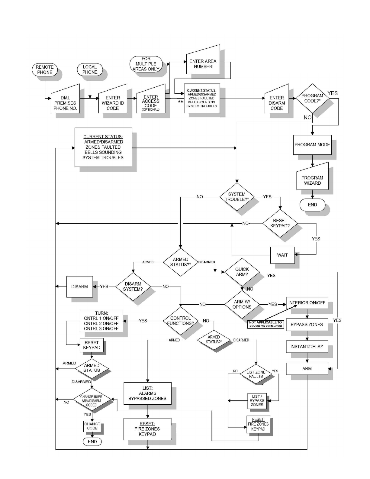
CONDENSED FLOW CHART
* INTERNAL DECISION
**
** PRESSING
(EXCEPT IN PROGRAM MODE)
RETURNS YOU HERE
(
AT ANY TIME
)
5
Page 6

WIZARD IIe WIRING DIAGRAM
SHUNT JP2 FOR EXPRESS
SERIES CONTROL PANELS
JP2
Wizard IIe, COVERS REMOVED
*
NOTE:
IF TOUCHTONES DO NOT WORK WHEN
ATTEMPTING LOCAL ACCESS, REVERSE
CONNECTIONS TO TIP & RING TERMINALS
(TERMINALS 10 & 11 AND 12 & 13).
LINE SEIZURE:
1 is low, the message
“Alarm system
communicating. Please try
again later, or enter Wizard
IIe entry number followed
by pound” will activate
when the local phone is
picked up.
(1) GEMINI SERIES CONTROL PANELS
If terminal
(4-WIRE KEYPAD BUS)
* DO NOT INSTALL SHUNT ON JP2
9
10
11
12
(2) EXPRESS SERIES CONTROL PANELS
(3-WIRE KEYPAD BUS)
* INSTALL SHUNT ON JP2
12
13
14
NOTES:
(1) GEMINI SERIES INCLUDE THE FOLLOWING CONTROL PANELS: GEM-P1632, GEM-P3200, GEM-P9600, SS-P3200 & SS-P9600
(2) EXPRESS SERIES INCLUDE THE FOLLOWING CONTROL PANELS: XP-400, XP-600, GEM-P400 & GEM-P800
6
Page 7

WIZARD IIe PROGRAMMING WORKSHEET
ENTER PROGRAM MODE
•
From a Remote Telephone:
automatically answers, go to step 1.
•
From a Local Telephone: Pick up the telephone and go to step 1.
PROGRAMMING STEPS
1. Enter the Wizard ID Code (Default = 55) and press #.
2. Enter the Acces Code (Default = 000000), if programmed, and press #.
3. When prompted for the Disarm Code, enter the Program Code (Default = 999) and press #.
4. When asked if you wish to load the Default Program, press #for Yes or press *for No.
5. When asked to enter the next command line, enter the command line (see Code 1 below) and its assoicated data
from these programming worksheets. To restart programming of any line press
PROGRAMMING TIPS
To Read Existing Data: Enter the Command Line only, then press
Example 1: To read existing Wizard ID Code, press
To Write New Data: Enter the Command Line and Data, then press
Example 2: To write Wizard ID Code “1234”, press
To Write and Read Back Data: Enter The Command Line and Data, then press
Example 3: To write Wizard ID Code “1234” and read it back, press
DO NOT ATTEMPT TO PROGRAM ANY RESERVED LOCATIONS.
IF NO ACTIVITY IS DETECTED WITHIN 30 SECONDS, THE WIZARD WILL HANG UP.
Dial the telephone number where Wizard is connected. When the Wizard or an Answering Machine
**
.
#
*11*#
#
.
.
*11*1234#
twice in rapid succession.
#
*11*1234##
.
.
.
CODES
Code 1: Wizard ID Code
Enter up to 4 digits in blank boxes at right.
Code 2: Access Code
Enter up to 6 digits in blank boxes at right.
Note: Entering all zeros will disable Access Code.
Code 3: Program Code
Enter up to 6 digits in blank boxes at right.
LIMITS
Limit 1: Number of Rings before Pickup
Enter 2 digits. Valid data is “01” through “15”.
NOTE: Refer to Standalone Telephone Controller
Limit 2: Maximum Area Number
Enter 2 digits. Valid data is “01” through “08”.
NOTE: For Express Series, (XP-400, XP-600,
GEM-P400 and GEM-P800) program “001” in this
location.
CODE 1:
CODE 2:
CODE 3:
LIMIT 1:
LIMIT 2:
(RESERVED)
*11* ##
*12*
*13*
*21* ##
*22*
COMMAND DATA
[Default = 5 5 ]
COMMAND DATA
##
[Default = 0 0 0 0 0 0]
COMMAND DATA
##
[Default = 999]
COMMAND DATA
[Default = 009]
COMMAND DATA
##
[Default = 001]
7
Page 8

#
Limit 3: Options
NOTE: Press
twice in rapid succession to Write and Read Back Data.
First, circle desired option number(s) at left, below:
[001] Disable Remote Access (Allows Local Phone Access Only)
[002] Panel Programmed for Keypad Fire and/or Keypad Aux Panic
NOTE: Refer to Panic Activation from Phone
[004] Enable Keypad Panic from Local Phone
NOTE: Refer to Panic Activation from Phone
[008] Enable Keypad Aux Panic from Local Phone
NOTE: Refer to Panic Activation from Phone
[016] Enable Keypad Fire Panic from Local Phone
NOTE:
Refer to Panic Activation from Phone
[032] Enable Auto-Reset Keypad (Wizard resets keypad every 90 seconds)
[064] Enable Area Select (Program for Multi-Area Systems)
[128] RESERVED - Do not program!
Then, enter 3-digit sum of circled numbers in blank boxes at right, above.
Valid data is “000” through “127”.
#
NOTE: Press
twice in rapid succession to Write and Read Back Data.
Limit 4: Telephone Company Answering Machine Override/”K” Keypad
(SECOND RING ACCESS FEATURE)
To enable this feature, enter “008”. To disable, enter “000”. Enter “016” to
enable the new “K-Series” style keypads.
NOTE: Refer to Telephone Company Answering Machine Override.
[000] Disable Telephone Company Answering Machine Override
[008] Enable Telephone Company Answering Machine Override
[016] Enable "K Series" style Keypad
LIMIT 3:
LIMIT 4:
COMMAND DATA
*23* #
[Default = 000]
COMMAND DATA
*24* #
[Default = 000]
COMMAND DATA
Limit 5: Number of Zones
NOTE: An attempt to bypass a zone number greater than that programmed here
LIMIT 5:
*25* #
[Default = 014]
will result in the error message, “Invalid. Please try again.”
COMMAND DATA
Limit 6: Wizard Keypad Address
NOTE:
For Napco Gemini Series Control Panels (GEM-P1632, GEM-P3200 and
GEM-P9600) Only; enter keypad address for Wizard. For Napco Express Series
Control Panels (GEM-P400, GEM-P800, XP-400 & XP-600) leave at default
LIMIT 6:
*26* #
[Default = 000]
“000”.
COMMAND DATA
Limit 7: Enable Control Panel Type
Enter “000” for Napco Gemini Series Control Panels (GEM-P1632, GEM-P3200
& GEM-P9600).
Enter “001” for Napco Express Series Control Panels (GEM-P400, GEM-P800,
LIMIT 7:
*27* #
[Default = 000]
XP-400 & XP-600).
CONTROL-OUTPUT DESCRIPTIONS
Enter up to 8 descriptors (from Descriptor Library) for each output in brackets below. Then, enter respective 3-digit code
in box beneath each descriptor.
#
twice in rapid succession to Write and Read Back Data.
CONTROL
*41*
NOTE: Press
[ ] [ ] [ ] [ ] [ ] [ ] [ ] [ ]
* * * * * * * *#
CONTROL
*42*
CONTROL
*43*
8
[ ] [ ] [ ] [ ] [ ] [ ] [ ] [ ]
* * * * * * * *#
[ ] [ ] [ ] [ ] [ ] [ ] [ ] [ ]
* * * * * * * *#
Page 9

ZONE DESCRIPTIONS
Enter up to 8 descriptors (from Descriptor Library) for each zone in brackets below. Then, enter respective 3-digit code in
box beneath each descriptor.
#
NOTE: Press
twice in rapid succession to Write and Read Back Data.
ZONE 1:
*501*
ZONE 2:
*502*
ZONE 3:
*503*
ZONE 4:
*504*
ZONE 5:
*505*
ZONE 6:
*506*
ZONE 7:
*507*
ZONE 8:
*508*
[ ] [ ] [ ] [ ] [ ] [ ] [ ] [ ]
* * * * * * * *#
[ ] [ ] [ ] [ ] [ ] [ ] [ ] [ ]
* * * * * * * *#
[ ] [ ] [ ] [ ] [ ] [ ] [ ] [ ]
* * * * * * * *#
[ ] [ ] [ ] [ ] [ ] [ ] [ ] [ ]
* * * * * * * *#
[ ] [ ] [ ] [ ] [ ] [ ] [ ] [ ]
* * * * * * * *#
[ ] [ ] [ ] [ ] [ ] [ ] [ ] [ ]
* * * * * * * *#
[ ] [ ] [ ] [ ] [ ] [ ] [ ] [ ]
* * * * * * * *#
[ ] [ ] [ ] [ ] [ ] [ ] [ ] [ ]
* * * * * * * *#
ZONE 9:
*509*
ZONE 10:
*510*
ZONE 11:
*511*
ZONE 12:
*512*
ZONE 13:
*513*
ZONE 14:
*514*
ZONE 15:
*515*
ZONE 16:
*516*
[ ] [ ] [ ] [ ] [ ] [ ] [ ] [ ]
* * * * * * * *#
[ ] [ ] [ ] [ ] [ ] [ ] [ ] [ ]
* * * * * * * *#
[ ] [ ] [ ] [ ] [ ] [ ] [ ] [ ]
* * * * * * * *#
[ ] [ ] [ ] [ ] [ ] [ ] [ ] [ ]
* * * * * * * *#
[ ] [ ] [ ] [ ] [ ] [ ] [ ] [ ]
* * * * * * * *#
[ ] [ ] [ ] [ ] [ ] [ ] [ ] [ ]
* * * * * * * *#
[ ] [ ] [ ] [ ] [ ] [ ] [ ] [ ]
* * * * * * * *#
[ ] [ ] [ ] [ ] [ ] [ ] [ ] [ ]
* * * * * * * *#
ZONE 17:
*517*
[ ] [ ] [ ] [ ] [ ] [ ] [ ] [ ]
* * * * * * * *#
9
Page 10

NOTE: Press
twice in rapid succession to Write and Read Back Data.
#
ZONE 18:
*518*
ZONE 19:
*519*
ZONE 20:
*520*
ZONE 21:
*521*
ZONE 22:
*522*
ZONE 23:
*523*
ZONE 24:
*524*
ZONE 25:
*525*
[ ] [ ] [ ] [ ] [ ] [ ] [ ] [ ]
* * * * * * * *#
[ ] [ ] [ ] [ ] [ ] [ ] [ ] [ ]
* * * * * * * *#
[ ] [ ] [ ] [ ] [ ] [ ] [ ] [ ]
* * * * * * * *#
[ ] [ ] [ ] [ ] [ ] [ ] [ ] [ ]
* * * * * * * *#
[ ] [ ] [ ] [ ] [ ] [ ] [ ] [ ]
* * * * * * * *#
[ ] [ ] [ ] [ ] [ ] [ ] [ ] [ ]
* * * * * * * *#
[ ] [ ] [ ] [ ] [ ] [ ] [ ] [ ]
* * * * * * * *#
[ ] [ ] [ ] [ ] [ ] [ ] [ ] [ ]
* * * * * * * *#
ZONE 26:
*526*
ZONE 27:
*527*
ZONE 28:
*528*
ZONE 29:
*529*
ZONE 30:
*530*
ZONE 31:
*531*
ZONE 32:
*532*
ZONE 33:
*533*
[ ] [ ] [ ] [ ] [ ] [ ] [ ] [ ]
* * * * * * * *#
[ ] [ ] [ ] [ ] [ ] [ ] [ ] [ ]
* * * * * * * *#
[ ] [ ] [ ] [ ] [ ] [ ] [ ] [ ]
* * * * * * * *#
[ ] [ ] [ ] [ ] [ ] [ ] [ ] [ ]
* * * * * * * *#
[ ] [ ] [ ] [ ] [ ] [ ] [ ] [ ]
* * * * * * * *#
[ ] [ ] [ ] [ ] [ ] [ ] [ ] [ ]
* * * * * * * *#
[ ] [ ] [ ] [ ] [ ] [ ] [ ] [ ]
* * * * * * * *#
[ ] [ ] [ ] [ ] [ ] [ ] [ ] [ ]
* * * * * * * *#
ZONE 34:
*534*
ZONE 35:
*535*
10
[ ] [ ] [ ] [ ] [ ] [ ] [ ] [ ]
* * * * * * * *#
[ ] [ ] [ ] [ ] [ ] [ ] [ ] [ ]
* * * * * * * *#
Page 11

NOTE: Press
twice in rapid succession to Write and Read Back Data.
#
ZONE 36:
*536*
ZONE 37:
*537*
ZONE 38:
*538*
ZONE 39:
*539*
ZONE 40:
*540*
ZONE 41:
*541*
ZONE 42:
*542*
ZONE 43:
*543*
[ ] [ ] [ ] [ ] [ ] [ ] [ ] [ ]
* * * * * * * *#
[ ] [ ] [ ] [ ] [ ] [ ] [ ] [ ]
* * * * * * * *#
[ ] [ ] [ ] [ ] [ ] [ ] [ ] [ ]
* * * * * * * *#
[ ] [ ] [ ] [ ] [ ] [ ] [ ] [ ]
* * * * * * * *#
[ ] [ ] [ ] [ ] [ ] [ ] [ ] [ ]
* * * * * * * *#
[ ] [ ] [ ] [ ] [ ] [ ] [ ] [ ]
* * * * * * * *#
[ ] [ ] [ ] [ ] [ ] [ ] [ ] [ ]
* * * * * * * *#
[ ] [ ] [ ] [ ] [ ] [ ] [ ] [ ]
* * * * * * * *#
ZONE 44:
*544*
ZONE 45:
*545*
ZONE 46:
*546*
ZONE 47:
*547*
ZONE 48:
*548*
ZONE 49:
*549*
ZONE 50:
*550*
ZONE 51:
*551*
[ ] [ ] [ ] [ ] [ ] [ ] [ ] [ ]
* * * * * * * *#
[ ] [ ] [ ] [ ] [ ] [ ] [ ] [ ]
* * * * * * * *#
[ ] [ ] [ ] [ ] [ ] [ ] [ ] [ ]
* * * * * * * *#
[ ] [ ] [ ] [ ] [ ] [ ] [ ] [ ]
* * * * * * * *#
[ ] [ ] [ ] [ ] [ ] [ ] [ ] [ ]
* * * * * * * *#
[ ] [ ] [ ] [ ] [ ] [ ] [ ] [ ]
* * * * * * * *#
[ ] [ ] [ ] [ ] [ ] [ ] [ ] [ ]
* * * * * * * *#
[ ] [ ] [ ] [ ] [ ] [ ] [ ] [ ]
* * * * * * * *#
ZONE 52:
*552*
ZONE 53:
*553*
[ ] [ ] [ ] [ ] [ ] [ ] [ ] [ ]
* * * * * * * *#
[ ] [ ] [ ] [ ] [ ] [ ] [ ] [ ]
* * * * * * * *#
11
Page 12

NOTE: Press
twice in rapid succession to Write and Read Back Data.
#
ZONE 54:
*554*
ZONE 55:
*555*
ZONE 56:
*556*
ZONE 57:
*557*
ZONE 58:
*558*
ZONE 59:
*559*
ZONE 60:
*560*
ZONE 61:
*561*
[ ] [ ] [ ] [ ] [ ] [ ] [ ] [ ]
* * * * * * * *#
[ ] [ ] [ ] [ ] [ ] [ ] [ ] [ ]
* * * * * * * *#
[ ] [ ] [ ] [ ] [ ] [ ] [ ] [ ]
* * * * * * * *#
[ ] [ ] [ ] [ ] [ ] [ ] [ ] [ ]
* * * * * * * *#
[ ] [ ] [ ] [ ] [ ] [ ] [ ] [ ]
* * * * * * * *#
[ ] [ ] [ ] [ ] [ ] [ ] [ ] [ ]
* * * * * * * *#
[ ] [ ] [ ] [ ] [ ] [ ] [ ] [ ]
* * * * * * * *#
[ ] [ ] [ ] [ ] [ ] [ ] [ ] [ ]
* * * * * * * *#
ZONE 62:
*562*
ZONE 63:
*563*
ZONE 64:
*564*
ZONE 65:
*565*
ZONE 66:
*566*
ZONE 67:
*567*
ZONE 68:
*568*
ZONE 69:
*569*
[ ] [ ] [ ] [ ] [ ] [ ] [ ] [ ]
* * * * * * * *#
[ ] [ ] [ ] [ ] [ ] [ ] [ ] [ ]
* * * * * * * *#
[ ] [ ] [ ] [ ] [ ] [ ] [ ] [ ]
* * * * * * * *#
[ ] [ ] [ ] [ ] [ ] [ ] [ ] [ ]
* * * * * * * *#
[ ] [ ] [ ] [ ] [ ] [ ] [ ] [ ]
* * * * * * * *#
[ ] [ ] [ ] [ ] [ ] [ ] [ ] [ ]
* * * * * * * *#
[ ] [ ] [ ] [ ] [ ] [ ] [ ] [ ]
* * * * * * * *#
[ ] [ ] [ ] [ ] [ ] [ ] [ ] [ ]
* * * * * * * *#
ZONE 70:
*570*
ZONE 71:
*571*
12
[ ] [ ] [ ] [ ] [ ] [ ] [ ] [ ]
* * * * * * * *#
[ ] [ ] [ ] [ ] [ ] [ ] [ ] [ ]
* * * * * * * *#
Page 13

NOTE: Press
twice in rapid succession to Write and Read Back Data.
#
ZONE 72:
*572*
ZONE 73:
*573*
ZONE 74:
*574*
ZONE 75:
*575*
ZONE 76:
*576*
ZONE 77:
*577*
ZONE 78:
*578*
ZONE 79:
*579*
[ ] [ ] [ ] [ ] [ ] [ ] [ ] [ ]
* * * * * * * *#
[ ] [ ] [ ] [ ] [ ] [ ] [ ] [ ]
* * * * * * * *#
[ ] [ ] [ ] [ ] [ ] [ ] [ ] [ ]
* * * * * * * *#
[ ] [ ] [ ] [ ] [ ] [ ] [ ] [ ]
* * * * * * * *#
[ ] [ ] [ ] [ ] [ ] [ ] [ ] [ ]
* * * * * * * *#
[ ] [ ] [ ] [ ] [ ] [ ] [ ] [ ]
* * * * * * * *#
[ ] [ ] [ ] [ ] [ ] [ ] [ ] [ ]
* * * * * * * *#
[ ] [ ] [ ] [ ] [ ] [ ] [ ] [ ]
* * * * * * * *#
ZONE 80:
*580*
ZONE 81:
*581*
ZONE 82:
*582*
ZONE 83:
*583*
ZONE 84:
*584*
ZONE 85:
*585*
ZONE 86:
*586*
ZONE 87:
*587*
[ ] [ ] [ ] [ ] [ ] [ ] [ ] [ ]
* * * * * * * *#
[ ] [ ] [ ] [ ] [ ] [ ] [ ] [ ]
* * * * * * * *#
[ ] [ ] [ ] [ ] [ ] [ ] [ ] [ ]
* * * * * * * *#
[ ] [ ] [ ] [ ] [ ] [ ] [ ] [ ]
* * * * * * * *#
[ ] [ ] [ ] [ ] [ ] [ ] [ ] [ ]
* * * * * * * *#
[ ] [ ] [ ] [ ] [ ] [ ] [ ] [ ]
* * * * * * * *#
[ ] [ ] [ ] [ ] [ ] [ ] [ ] [ ]
* * * * * * * *#
[ ] [ ] [ ] [ ] [ ] [ ] [ ] [ ]
* * * * * * * *#
ZONE 88:
*588*
ZONE 89:
*589*
[ ] [ ] [ ] [ ] [ ] [ ] [ ] [ ]
* * * * * * * *#
[ ] [ ] [ ] [ ] [ ] [ ] [ ] [ ]
* * * * * * * *#
13
Page 14

NOTE: Press
twice in rapid succession to Write and Read Back Data.
#
ZONE 90:
*590*
ZONE 91:
*591*
ZONE 92:
*592*
ZONE 93:
*593*
ZONE 94:
*594*
ZONE 95:
*595*
ZONE 96:
*596*
[ ] [ ] [ ] [ ] [ ] [ ] [ ] [ ]
* * * * * * * *#
[ ] [ ] [ ] [ ] [ ] [ ] [ ] [ ]
* * * * * * * *#
[ ] [ ] [ ] [ ] [ ] [ ] [ ] [ ]
* * * * * * * *#
[ ] [ ] [ ] [ ] [ ] [ ] [ ] [ ]
* * * * * * * *#
[ ] [ ] [ ] [ ] [ ] [ ] [ ] [ ]
* * * * * * * *#
[ ] [ ] [ ] [ ] [ ] [ ] [ ] [ ]
* * * * * * * *#
[ ] [ ] [ ] [ ] [ ] [ ] [ ] [ ]
* * * * * * * *#
AREA DESCRIPTIONS
Enter up to 8 descriptors (from Descriptor Library) for each area in brackets below. Then, enter respective 3-digit code in
box beneath each descriptor.
#
twice in rapid succession to Write and Read Back Data.
AREA 1:
*61*
AREA 2:
*62*
AREA 3:
*63*
AREA 4:
*64*
AREA 5:
*65*
AREA 6:
*66*
NOTE: Press
[ ] [ ] [ ] [ ] [ ] [ ] [ ] [ ]
* * * * * * * *#
[ ] [ ] [ ] [ ] [ ] [ ] [ ] [ ]
* * * * * * * *#
[ ] [ ] [ ] [ ] [ ] [ ] [ ] [ ]
* * * * * * * *#
[ ] [ ] [ ] [ ] [ ] [ ] [ ] [ ]
* * * * * * * *#
[ ] [ ] [ ] [ ] [ ] [ ] [ ] [ ]
* * * * * * * *#
[ ] [ ] [ ] [ ] [ ] [ ] [ ] [ ]
* * * * * * * *#
AREA 7:
*67*
AREA 8:
*68*
14
[ ] [ ] [ ] [ ] [ ] [ ] [ ] [ ]
* * * * * * * *#
[ ] [ ] [ ] [ ] [ ] [ ] [ ] [ ]
* * * * * * * *#
Page 15

THE FOLLOWING STATEMENT IS REQUIRED BY THE FCC.
This equipment generates and uses radio-frequency energy and, if not
installed and used properly, that is, in strict accordance with the
manufacturer's instructions, may cause interference to radio and
television reception. It has been type tested and found to comply with the
limits for a Class-B computing device in accordance with the
specifications in Subpart J of Part 15 of FCC Rules, which are designed
to provide reasonable protection against such interference in a
residential installation.
However, there is no guarantee that interference will not occur in a
particular installation. If this equipment does cause interference to radio
or television reception, which can be determined by turning the
equipment off and on, the user is encouraged to try to correct the
interference by one or more of the following measures: reorient the
receiving antenna; relocate the computer with respect to the receiver;
move the computer away from the receiver; plug the computer into a
different outlet so that computer and receiver are on different branch
circuits.
If necessary, the user should consult the dealer or an experienced
radio/television technician for additional suggestions. The user may find
the following booklet prepared by the Federal Communications
Commission helpful: “How to Identify and Resolve Radio-TV Interference
Problems.” This booklet is available from the U.S. Government Printing
Office, Washington, DC 20402; Stock No. 004-000-00345-4.
If a digital communicator is connected to a telephone line, do not notify
the telephone company. It is no longer necessary to call the telephone
company to notify it of the registration and ringer equivalence numbers of
any telephone instrument being connected to the public switched
telephone network. The telephone company will call and request this
information if a need arises in the future.
RINGER EQUIVALENCE NUMBER
The FCC registration label, found on the printed-circuit board and on the
bottom of your telephone sets, includes the ringer equivalence number
(REN). This is a representation of the electrical load that will be applied
to your telephone line. This system has a ringer equivalence of zero.
Therefore, it does not affect the load of the telephone company central
office equipment when your telephones ring. The telephone line
servicing your premises will not operate properly if the total ringer load
exceeds the capability of the central office equipment. That is, if too
many ringers are connected to the line, there may be insufficient energy
to ring your telephones. If the ringer load is excessive, you may also
have difficulty dialing telephone numbers.
If you want to know the total REN allowed for your telephone line, you
may call your telephone company. However, as a rule of thumb, a total
REN of five (5) should permit normal operation of your telephone sets
and equipment. To determine the total ringer load, list the REN of each
of your telephone sets or devices connected to your telephone line. Add
these numbers; the result is the total REN for your line. If this number
exceeds 5, you may want to consult your telephone company to
determine whether or not proper operation of your equipment is possible.
RIGHTS OF THE TELEPHONE COMPANY
If your equipment causes harm to the telephone network, the telephone
company may discontinue your service temporarily. If possible, they will
notify you in advance. But if advance notice is not practical, you will be
notified as soon as possible. You will be given the opportunity to correct
the situation and you will be informed of your right to file a complaint with
the FCC.
Your telephone company may make changes in its facilities, equipment,
operations or procedures that could affect the proper function of your
communicator. If they do, you will be notified in advance to give you an
opportunity to maintain uninterrupted service.
NOTES
15
Page 16

NAPCO LIMITED WARRANTY
NAPCO SECURITY SYSTEMS, INC. (NAPCO)
warrants its products to be free from manufacturing
defects in materials and workmanship for thirty-six
months following the date of manufacture. NAPCO will,
within said period, at its option, repair or replace any
product failing to operate correctly without charge to the
original purchaser or user.
This warranty shall not apply to any equipment, or
any part thereof, which has been repaired by others,
improperly installed, improperly used, abused, altered,
damaged, subjected to acts of God, or on which any
serial numbers have been altered, defaced or removed.
Seller will not be responsible for any dismantling or
reinstallation charges.
THERE ARE NO WARRANTIES, EXPRESS OR
IMPLIED, WHICH EXTEND BEYOND THE
DESCRIPTION ON THE FACE HEREOF. THERE IS
NO EXPRESS OR IMPLIED WARRANTY OF
MERCHANTABILITY OR A WARRANTY OF FITNESS
FOR A PARTICULAR PURPOSE. ADDITIONALLY,
THIS WARRANTY IS IN LIEU OF ALL OTHER
OBLIGATIONS OR LIABILITIES ON THE PART OF
NAPCO.
Any action for breach of warranty, including but not
limited to any implied warranty of merchantability, must
be brought within the six months following the end of the
warranty period. IN NO CASE SHALL NAPCO BE
LIABLE TO ANYONE FOR ANY CONSEQUENTIAL OR
INCIDENTAL DAMAGES FOR BREACH OF THIS OR
ANY OTHER WARRANTY, EXPRESS OR IMPLIED,
EVEN IF THE LOSS OR DAMAGE IS CAUSED BY THE
SELLER'S OWN NEGLIGENCE OR FAULT.
In case of defect, contact the security professional
who installed and maintains your security system. In
order to exercise the warranty, the product must be
returned by the security professional, shipping costs
prepaid and insured to NAPCO. After repair or
replacement, NAPCO assumes the cost of returning
products under warranty. NAPCO shall have no
obligation under this warranty, or otherwise, if the
product has been repaired by others, improperly
installed, improperly used, abused, altered, damaged,
subjected to accident, nuisance, flood, fire or acts of
God, or on which any serial numbers have been altered,
defaced or removed. NAPCO will not be responsible for
any dismantling, reassembly or reinstallation charges.
This warranty contains the entire warranty. It is the
sole warranty and any prior agreements or
representations, whether oral or written, are either
merged herein or are expressly cancelled. NAPCO
neither assumes, nor authorizes any other person
purporting to act on its behalf to modify, to change, or to
assume for it, any other warranty or liability concerning
its products.
In no event shall NAPCO be liable for an amount in
excess of NAPCO's original selling price of the product,
for any loss or damage, whether direct, indirect,
incidental, consequential, or otherwise arising out of any
failure of the product. Seller's warranty, as hereinabove
set forth, shall not be enlarged, diminished or affected by
and no obligation or liability shall arise or grow out of
Seller's rendering of technical advice or service in
connection with Buyer's order of the goods furnished
hereunder.
NAPCO RECOMMENDS THAT THE ENTIRE
SYSTEM BE COMPLETELY TESTED WEEKLY.
Warning: Despite frequent testing, and due to, but
not limited to, any or all of the following; criminal
tampering, electrical or communications disruption, it is
possible for the system to fail to perform as expected.
NAPCO does not represent that the product/system may
not be compromised or circumvented; or that the product
or system will prevent any personal injury or property
loss by burglary, robbery, fire or otherwise; nor that the
product or system will in all cases provide adequate
warning or protection. A properly installed and
maintained alarm may only reduce risk of burglary,
robbery, fire or otherwise but it is not insurance or a
guarantee that these events will not occur.
CONSEQUENTLY, SELLER SHALL HAVE NO
LIABILITY FOR ANY PERSONAL INJURY, PROPERTY
DAMAGE, OR OTHER LOSS BASED ON A CLAIM THE
PRODUCT FAILED TO GIVE WARNING. Therefore, the
installer should in turn advise the consumer to take any
and all precautions for his or her safety including, but not
limited to, fleeing the premises and calling police or fire
department, in order to mitigate the possibilities of harm
and/or damage.
NAPCO is not an insurer of either the property or
safety of the user's family or employees, and limits its
liability for any loss or damage including incidental or
consequential damages to NAPCO's original selling
price of the product regardless of the cause of such loss
or damage.
Some states do not allow limitations on how long an
implied warranty lasts or do not allow the exclusion or
limitation of incidental or consequential damages, or
differentiate in their treatment of limitations of liability for
ordinary or gross negligence, so the above limitations or
exclusions may not apply to you. This Warranty gives
you specific legal rights and you may also have other
rights which vary from state to state.
16
 Loading...