

NAPCO StarLink Connect, StarLink Connect SLECDMA-CB-TF-C, StarLink Connect SLECDMA-CB-C Installation Instructions Manual
Page 1
333 Bayview Avenue Amityville, New York 11701
For Sales and Repairs, (800) 645-9445
For Technical Service, (800) 645-9440 or visit us at
(Note: Technical Service is for security professionals only)
http://tech.napcosecurity.com/
Publicly traded on NASDAQ Symbol: NSSC
© NAPCO 2018
StarLink™ Connect Series
SLECDMA-CB-C & SLECDMA-CB-TF-C
Multi-Function Alarm Communicators
INSTALLATION INSTRUCTIONS
WI2247ALF 8/18
OVERVIEW
The StarLink™ Connect models SLECDMA-CB-C and
SLECDMA-CB-TF-C are multi-function Commercial / Resi-
dential Burglary and Residential Fire alarm radio communicators and supervised system interface modules. They provide several options to the user:
1. A monitoring path to a central station through a digital
CDMA radio and optionally through a TCP/IP network to
the Internet using a hardwired or optional Wi-Fi connec-
If required, mount the unit to a single-, dual-, or three-gang
StarLink SLE Series radios use proprietary data-capture
The StarLink radio model names are as follows:
tion;
2. Notification alerts of alarm system changes to a mobile
device. Notifications use iBridge Messenger SMS text
messaging and/or emails to inform the user and/or dealer of system state changes. For this release, these notifications are enabled in the iBridge Connected Home
Services website at http://ibridge.napconoc2.com;
3. Both radio models are compatible with most 12VDC
alarm control panels, including Honeywell and DSC
(always adhere to the documentation provided by the
control panel manufacturer). Residing in the Windows
System Tray, the StarLink Connect application allows
you to use your customary control panel communication
software for remote programming and communication:
DSC DLS
Honeywell Compass
®
NAPCO control panels are programmed in the tradition-
al way using PCD-Windows Quickloader software.
StarLink Connect is available on the enclosed CD.
electrical box and route the wires through the back knockout(s), or as specified by local codes. See WI2140 for pro-
gramming instructions (all manuals are available for
download at http://tech.napcosecurity.com/).
technology that captures the alarm report from the control
panel and transmits the alarm signals to the SLE Control
Center (the Napco "NOC"); the alarm signals are then forwarded to ANY central station via Contact ID or Sur-Gard
System II or Sur-Gard System V central station receivers via
TCP/IP using standard line security. The SLE Control Center reports a trouble signal in the event that the network does
not receive the expected supervision signal from the wireless communicator. In addition, both StarLink radio models
can be powered directly from the control panel.
SLECDMA-CB-C - Commercial / Residential Burglary and
Residential Fire Network Compatible CDMA alarm capture radio communicator in white metal housing. Powered directly from control panel (no power supply, no
transformer).
SLECDMA-CB-TF-C - Commercial / Residential Burglary
and Residential Fire Network Compatible CDMA alarm
capture radio communicator in white metal housing. Includes SLE-ULPS-R power supply and TRF12/T123
plug-in 16.5V / 20VA transformer.
ADDITIONAL COMPONENTS
In addition to the models listed above, the
following sub-assemblies are available:
SLE-WIFI-MODULE - Allows your StarLink™
device to connect to the Internet by means of a wireless
(Wi-Fi) link, eliminating a wired Ethernet cable connection.
SLE-DLCBL - Download Cable, 6 feet.
SLE-ANTEXT30 - Extended antenna with 30 feet of cable.
SLE-ANTEXT50 - Extended antenna with 50 feet of cable.
SLE-ANTEXT75 - Extended antenna with 75 feet of cable.
(Any suitable external cellular antenna is permitted by
UL). Always follow the manufacturer's installation instructions. Note: Antennas are not Listed by UL. For
3/4G radios where an External Antenna needs to be
installed outside of the room in which the radio is installed (maximum 30 meters (98 feet) in Residential applications), please use RF Transmitter Board
9GPS5320EXAPSLD available from our Customer Service Department, if not provided. The
9GPS5320EXAPSLD is identified by "two red dots" located on the lower right corner of the board. See
WI2222 included with the 9GPS5320EXAPSLD for the
simple installation procedure.
SPECIFICATIONS
The following specifications apply to all StarLink radio mod-
els in these installation instructions unless otherwise stated:
Electrical Ratings for +12V (both models powered by the
control panel)
Input Voltage: 10-15VDC (power-limited output from con-
trol panel). Do NOT connect to full-wave rectified (FWR)
power.
Input Current:
Electrical Ratings for the IN 1 Burg/Fire Input:
SLECDMA-CB-C standby current: 100mA (110mA
with telco EOLR)
SLECDMA-CB-TF-C standby current : 100mA
(110mA with telco EOLR)
Transmission current (all models): 200mA max.
Input Voltage: 9-15VDC.
Maximum Input Current: Up to 2mA from control panel
supply circuit
StarLink™ Connect SLECDMA-CB Series Alarm Communicators -- Installation Instructions 1
Page 2
ETHERNET
Electrical Ratings for IN 2 and IN 3:
Maximum Loop Voltage: 15VDC max.
Maximum Loop Current: 1.2mA
End of Line Resistor (EOLR) Value: 10K
Electrical Ratings for 3 PGM Outputs:
Open Collector Outputs: Maximum Voltage 3V when
active; 15V maximum when not active
Maximum PGM Sink Current: 50mA (up to 15VDC)
Physical (W x H x D)
Metal Housing: 11½ x 9½ x 3½" (29.2 x 24.1 x 8.9cm)
Mounting: Metal housing includes two keyhole slots for
wall mounting (see measurements on page 15)
Environmental
Operating Temperature: 0°C - 49°C (32°F - 120°F)
Humidity: Maximum 93% Non-Condensing
Indoor / dry location use only
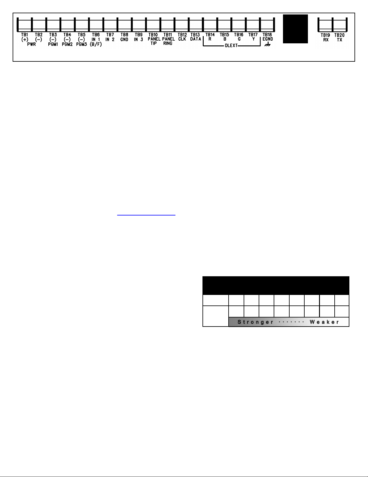
TERMINAL DESCRIPTIONS
Configure all inputs and outputs using the Management
Center (the Napco "NOC" located at http://NapcoNoc2.com).
Located at the bottom of the StarLink radio PC board, the 20
terminals are described as follows:
TB1: PWR (+) +10 - 15VDC.
Do NOT connect to FWR power.
TB2: PWR (–)
TB3: PGM1 (–): Open collector output. PGM1 is nor-
mally on (active low). When it is triggered (for example, a trouble is detected) it becomes open collector/
high. To have a zone dedicated to an StarLink radio
trouble, insert one side of the end of line resistor into
this PGM1 terminal, and wire the other side of the
resistor to the positive terminal of the zone.
TB4: PGM2 (–): Open collector output. This output is
normally open collector / high. When a report fails to
communicate anywhere in the communications path,
the output is active low.
TB5: PGM3 (–): Open collector output. This output is
normally open collector / high. Use the Napco "NOC"
to configure options for PGM activation.
TB6: IN 1: Active high input for wiring to the control
panel bell output. When this input detects a pulsing
temporal 3 high, it sends a Fire alarm; a pulsing temporal 4 (CO Alarm), a CO alarm is sent. For this input to report to a central station, the StarLink radio
must be configured with the central station telephone
number and correct reporting formats and codes.
TB7: IN 2: See TB9, below .
TB8: GND: Common ground terminal.
TB9: IN 3: Both terminals IN 2 and IN 3 default to 'User
Defined'; no end-of-line resistor supervision required.
Wire the common ground terminal GND (terminal
TB8) to the relay common. When used as ar m/
disarm status input, a low indicates "armed" and a
high indicates "disarmed". For these inputs to report
to a central station, the radio must be configured with
the central station telephone number and correct reporting formats and codes.
TB10: PANEL TIP: See wiring diagram(s ).
TB11: PANEL RING: See wiring diagram(s).
TB12: CLK: See wiring diag ram(s).
TB13: DATA: See wiring diagram(s).
TB14: R: Red w ire. See TB17.
TB15: B: Blue wire. See TB17.
TB16: G: Green w ire. See TB17.
TB17: Y: Yellow wire. Do NOT connect if using the SLE
-DLCBL Download Cable.
TB18: EGND: Earth ground (optional)
TB19: RX: See wiring diagram(s).
TB20: TX: See wiring diagram(s).
LED DESCRIPTIONS
The PC board contains several LEDs, as follows:
GREEN RF SIGNAL STRENGTH LED
Labeled "D3", this LED is located at the lower right corner
of the PC board (see image).
Every 30 seconds, the StarLink radio receiver section
turns on and listens to the cell tower. Depending on the
signal strength detected, it will blink the Signal Strength
LED from 1 to 8 times, providing a signal strength indicator
that is updated constantly and is always displayed. Refer
to the Coverage Table:
LED Blinks 8 7 6 5 4 3 2 1
Green LED Operation
Signal strength (as received by the radio) is displayed by
this LED blinking 1 to 8 times at a constant rate (with a
short delay between blink cycles). Acceptable power level
is greater than or equal to -91dBm (minimum 4 blinks at
the mounting location).
YELLOW OPERATIONAL STATUS LED (Radio)
Labeled "D4", this yellow LED is located at the bottom right
of the PC board. Operation is as follows:
Normal Standby Condition:
Blinks on momentarily every 10 seconds: Unit is in
Processing Alarm Conditions:
When processing an alarm, this yellow LED will blink
GREEN RF SIGNAL STRENGTH LED
RADIO RECEIVER COVERAGE TABLE
Power
(dBm)
-55 -65 -75 -85 -91 -95 -99 -105
standby waiting for an alarm to report.
2 StarLink
™
Connect SLECDMA-CB Series Alarm Communicators -- Installation Instructions
Page 3
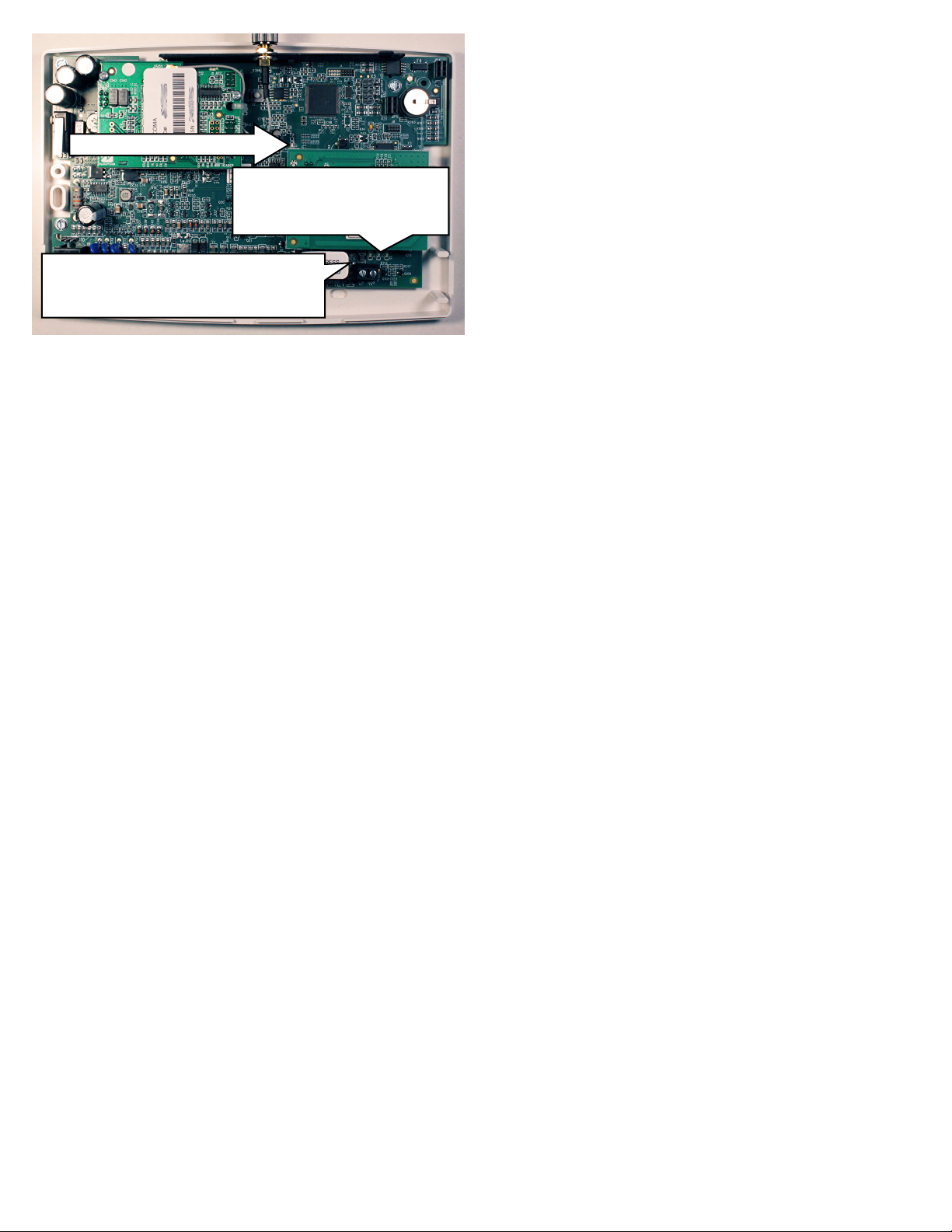
DL: RED DIAGNOSTIC LED
D4: YELLOW OPERATIONAL STATUS
D3: GREEN RF SIGNAL STRENGTH
D5: RED TROUBLE
DS14: GREEN IP NETWORK TYPE OR QUALITY
DS15 YELLOW IP NETWORK STATE
DS16 RED IP NETWORK TROUBLES
LED LOCATIONS
variably during each part of the process (dialing, handshaking, data transmission, etc.).
This yellow LED will light when communicating with the
phone app and when notifications are transmitted.
RED TROUBLE LED
Labeled "D5", this LED is located at the bottom right of the
PC board. Operation is as follows:
1 Blink: Low Aux Power input voltage
2 Blinks: Battery trouble
3 Blinks: Alarm report Failed to Communicate (will
restore only when both paths are operational)
4 Blinks: RF trouble (antenna connection or cellular
registration)
5 Blinks: Radio poll or check-in failure (radio only).
The unit must only fail on one path to trigger the trouble,
but for the trouble to clear, unit requires both IP and radio polling / checkins to be operational.
6 Blinks: Unit disabled (reporting or control panel
downloading not allowed)
7 Blinks: Unit was shutdown and has no functionali-
ty; requires a restart (full power down and full power up
sequence) to restore operation.
RED DIAGNOSTIC LED
Labeled "D7", this LED is located in the middle of the PC
board. One blink indicates a weak or non-existent signal
from the network (green LED is off). If this red LED is
blinking in any other manner, please contact technical support.
NETWORK CONNECTION LEDs
Labeled "DS14" (green), "DS15" (yellow) and
"DS16" (red), these LEDs are located at the bo ttom
right of the PC board.
The green LED labeled "DS14" describes the IP network
connection type or the connection quality, as follows:
When DS14 is off = No network cable detected
When DS14 is flashing rapidly = No IP connection
(occurs just after power on while trying to obtain an IP
address; therefore has priority over any other green
flashing LEDs)
When DS14 is flashing slowly = Normal operation:
1 Slow Blink: Static IP Address (as programed by
the NOC)
2 Slow Blinks: DHCP (default)
3 Slow Blinks: Auto IP (if unable to acquire DHCP
address, after 5 minutes radio will convert to Auto IP.
The Yellow LED labeled "DS15" describes the status of
the IP network.
When DS15 is off = No power
When DS15 is flashing rapidly = Push button on Wi-Fi
module is being pressed
When DS15 is flashing steady with 1 quick blink off eve-
ry 2 seconds = Reporting signal to NOC
When DS15 is flashing steady with 2 quick blinks off
every 2 seconds = Downloading to control panel or the
module
When DS15 is flashing slowly:
1 Slow Blink: Ethernet available (must detect that
the CAT5 cable is connected and must be connected
to the Internet via customer router, etc.)
2 Slow Blinks: Wi-Fi Station Mode
3 Slow Blinks: Wi-Fi APN Mode (Access Point)
The red LED labeled "DS16" describes the IP network
troubles.
When DS16 is off = No network troubles detected
When DS16 is flashing rapidly = No IP connection
(occurs just after power up while the radio tries to obtain
a DHCP IP address
When DS16 is flashing slowly:
1 Slow Blink: No network cable detected
2 Slow Blinks: No network cable access to the
Internet (mutually exclusive with "1 Blink"). If the radio
is configured for only an Ethernet connection (no WiFi) and the Ethernet cable is connected but the router
is non-functional, the radio will detect the loss of access to the Internet within a programmable amount of
seconds. The default of 500 seconds (8-1/3 minutes)
is intended to display a trouble to the installer sooner
in case the account is set for 1-hour, 24-hour or 7-day
Supervisory Failure
3 Slow Blinks: Ethernet failed to communicate
4 Slow Blinks: Ethernet poll / chec k -in failure
5 Slow Blinks: Wi-Fi enabled but the SLE-WIFI-
MODULE is not detected
6 Slow Blinks: = No Wi -Fi access to the Internet.
May occur when the Wi-Fi and the network cable each
access the Internet via separate means (for example
two different routers). Note: This indication may be
combined with the "2 Blinks" indication if both the Wi-
Fi and network cable use the same ISP.
7 Slow Blinks: Wi-Fi failed to communicate
8 Slow Blinks: Wi-Fi poll / checkin fail
9 Slow Blinks: Wi-Fi serial data error or no serial
data response
10 Slow Blinks: Wi-Fi Security / Authentication failed
OTHER LEDs
Labeled "D607" (green) and "D606" (red), these LEDs indi-
StarLink™ Connect SLECDMA-CB Series Alarm Communicators -- Installation Instructions 3
Page 4

cate the status when connected to a DSC or Honeywell
control panel (when connected to a NAPCO control panel, both LEDs remain off). The LED labeled "D44" is not
used.
When connected to a Honeywell control panel, D607
(green) flashes once every 5 seconds, and:
When D606 (red) is off = No troubles
When D606 (red) is flashing rapidly = Bootloader mode
When D606 (red) is flashing 1 = Keypad bus fault
When D606 (red) is flashing 3 = Configuration memory
error
When connected to a DSC control panel, D607 (green)
flashes twice every 5 seconds and:
When D606 (red) is off = No troubles
When D606 (red) is flashing rapidly = Bootloader mode
When D606 (red) is flashing 1 = Keypad bus fault
(radio terminals 12 and 13)
When D606 (red) is flashing 2 = DSC download con-
nection faulted (radio terminals 19 and 20)
SUPPLYING POWER TO THE RADIO
Control panels can provide power through their Auxiliary
Power terminals if the available standby current is reduced
by the SLE standby power. If the control panel Auxiliary
Power is insufficient to power the communicator, a suitably
rated power limited Residential Fire or Commercial / Residential Burglary power supply may be used (such as the
model GEMC-12V2APS).
RADIO INSTALLATION STEPS
STEP 1: ACCOUNT REGISTRATION
Create a new account and register specific StarLink radio
modules at www.NapcoComNet.com. Accounts and modules registered via the Internet are enabled for activation
within 24 hours.
STEP 2: SELECT A MOUNTING LOCATION
The mounting location should be indoors within the protected area and selected based on RF performance. It is
HIGHLY recommended that the installer carefully adhere to
the following recommendations BEFORE any wires are
installed.
Generally, high locations are best. DO NOT mount ra-
dio in basements or below grade as unpredictable performance may result.
DO NOT mount the radio in non-climate controlled envi-
ronments (i.e. attics may become extremely hot in summer, garages may become extremely cold in winter).
Avoid mounting locations within 3 feet of AC power
lines, fluorescent light fixtures, or large metal objects (air
conditioners, metal garage doors, etc.) as these locations have been shown to have a detrimental effect on
signal strength.
A fair amount of care may be required to mount the ra-
dio so as to achieve an optimal RF path. The installer
should spend as much time as needed to obtain the
highest signal level possible.
a. Before applying power, be sure to connect the
antenna. Temporarily connect power to the radio from a fully charged 12V (4AH minimum) battery. DO NOT mount the StarLink radio at this time.
Press Tamper switch to send a signal.
b. Position the unit in the desired mounting location,
with antenna oriented vertically. The signal strength
is displayed by the Green "Signal Strength LED"
labeled "D3" (located at the lower right corner of the
PC board). The CDMA radio tower signal strength
may fluctuate from day to day, therefore it is best to
try to find a mounting location where the LED provides a minimum of 4 blinks.
c. Once a location has been selected based on signal
coverage, permanently secure the unit using #8
screws (not supplied) in the two mounting holes.
WARNING: To ensure user safety and to satisfy FCC
RF exposure requirements, this unit must be installed so
that a minimum separation distance of 60cm (24") is always maintained between the antenna of the transmitting
device and nearby persons.
STEP 3: WIRING
22-gauge wire may be used if mounted up to 50 feet from
the control panel, and 18-gauge wire should be used for up
to 100 feet. Reference the wiring diagrams further in this
manual. All wiring methods must be performed in accordance with NFPA70, Articles 725, and 800
STEP 4: APPLY POWER
Attach antenna before applying power !
Apply 12 VDC to terminals 1 and 2.
STEP 5: SIGNAL VERIFICATION
After triggering channels, use the StarLink radio Signal Ver-
ification to ensure that the StarLink radio Network has
properly received the signals.
Verify Online: To verify that the signals have been
received by the StarLink radio Network online, go to
http://NapcoNoc2.com, log in with your Username and
Password, enter your Company ID number and the
StarLink Radio Number, then click Signal Log.
IMPORTANT: Verify that the signals transmitted by the
StarLink radio have been properly received by your central
station before leaving the premises.
NOTE: This equ ipment has been test ed and found to
comply with the limits for a Class B Unintentional Radiator,
pursuant to Part 15 of the FCC Rules. These limits are
designed to provide reasonable protection against harmful
interference in a residential installation. This equipment
generates, uses, and can radiate radio frequency energy
and, if not installed and used in accordance with the Instruction Manual, may cause harmful interference to radio
communications. However, there is no guarantee that interference will not occur in a particular installation. If this
equipment does cause harmful interference to radio or television reception, which can be determined by turning the
equipment off and on, the user is encouraged to try to cor-
4 StarLink
™
Connect SLECDMA-CB Series Alarm Communicators -- Installation Instructions
Page 5
rect the interference by one of more of the following
measures: 1. Reorient or relocate the receiving antenna; 2.
Increase the separation between the equipment and receiver; 3. Connect the equipment into an outlet on a circuit different from that to which the receiver is connected; 4. Consult
the dealer or an experienced radio/TV technician for help.
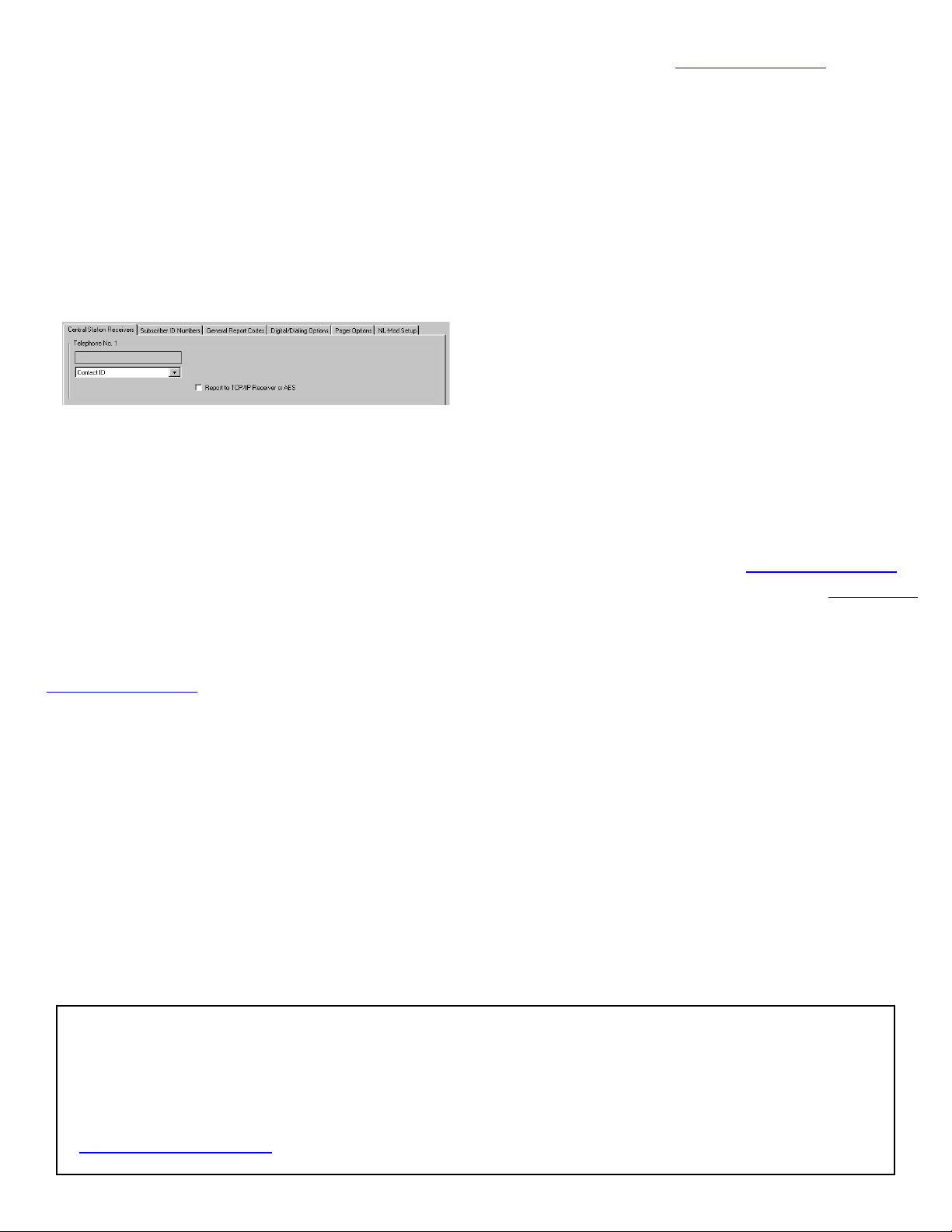
NAPCO CONTROL PANEL PROGRAMMING
To program the central station receiver reporting format,
use PCD-Windows Quickloader download software. Open
the Digita l Communications screen, Central Station Receiv-
ers tab, as shown in the following image:
A "Point ID" (also called "Contact ID") receiver format pro-
gramming example:
The radio can transmit to any central station capable of re-
ceiving Contact ID or the DSC Sur-Gard System II or SurGard System V central station receivers via TCP/IP.
Note: A receiver reporting format must be entered for
each telephone number used, but each telephone number
may be assigned a different format.
CAUTION: The installer should always be certain an area
code is programmed into the control panel.
Optional: If you wish the StarLink radio to report a code
and zone number (Contact ID by default) to the central station
in response to a triggered input event, see the table on page
6. Note: These event codes and zone numbers c an be
changed from the Management Center screen (located at
http://NapcoNoc2.com).
Programming StarLink Radio Troubles
It is required that if a StarLink radio or control panel trouble is
detected, that it is reported to the central station.
When the StarLink radio detects and sends a trouble to the
control panel, the control panel must be programmed to annunciate this trouble. The radio can detect multiple troubles
as indicated by the "Red Trouble LED" ("D5"). For these
troubles to be annunciated at the control panel, there are
several methods, some of them are configurable at the Management Center screen (http://NapcoNoc2.com):
Wire the radio PGM1 output to a dedicated control panel
zone (input) to annunciate the trouble (activate a trouble
sounder) when an open is detected. With Napco control
panels, program a dedicated zone for Day Zone, Minisounder on Alarm and No bell on Alarm. Wire the zone as
indicated in the wiring diagrams further in this manual.
For radio models powered by the control panel Aux Power
terminals, wire the radio directly to the PGM1 output of the
control panel (program the radio to report all troubles on
PGM1).
You can also wire to the positive terminal of the dedicated
zone on a GEMC-EZM8. Thus when a radio trouble is detected, the radio PGM activates the control panel zone, and
the control panel generates a trouble.
StarLink Panel / Radio Supervision of Tip/Ring Wiring
The StarLink radio connection to the control panel shall be
supervised with local trouble annunciation and report to the
central station if the Tip/Ring wiring is cut or shorted.
For local annunciation of radio troubles, the control panel
must be programmed for Telco line supervision that will produce a local trouble at the premises (refer to control panel
programming).
To report the radio trouble to the central station:
1. Program the unit (select "Y") for the "Tip/Ring Wiring
Fault Report" feature located in the Advanced Features
screen of the Napco "NOC" (at http://NapcoNoc2.com).
2. Install the supplied 10K EOLR across the control panel
terminals normally intended to be wired to the home telephone if Telco service was used (shown in the wiring
diagram examples).
Note: Some control panels may require a different dura-
tion than the default time of 3 minutes. See also the alternate supervision method described below, "Telco Line to
Alarm Panel Supervision (For Primary Mode Only)".
Supervision Time Schedule Considerations
If a status change (alarm trouble, etc.) is transmitted, the ra-
dio supervision timer is restarted.
For example, if a status change is sent, the next regular su-
pervision transmission will occur at the interval determined
by your rate plan.
Telco Line to Alarm Panel Supervision
A 10K ohm resistor (5% tolerance) can be placed across the "house side" of the telephone line circuit
(see wiring diagrams). Use this resistor instead of using a relay on the alarm control panel to trip an input
on the radio to supervise the connection between the alarm control panel telco circuit and the radio.
REMEMBER: Enable the feature " Tip / Ring Wiring Fault Report" in the NOC
(www.NapcoComNet.com) to supervise the telephone line connection to the control panel.
StarLink™ Connect SLECDMA-CB Series Alarm Communicators -- Installation Instructions 5
Page 6

JUMPER DESCRIPTIONS
Jumper block labeled "X5"; from top to bottom, as
detailed in the following table. Note: Contact ID is
always available in response to a Contact ID
handshake.
Jumper Block "X5" Options
Jumper block labeled "X5" contains 5 jumper terminals; from top
(labeled "1") to bottom (labeled "5") as follows:
Jumper ON
Not used; do NOT install jumper 1 Not used; do NOT install jumper
4/2 with Checksum Pulse Format 2
Not used; do NOT install jumper 3 Not used; do NOT install jumper
10K EOLR Required 4
10K EOLR Required 5
The SLE series radios are compatible with 4/2 Pulse
Dialing formats with 10pps, 20pps, and 40pps with and
without checksum, either 1400Hz or 2300Hz
handshake / kissoff. See page 15 for table of formats.
Refer to WI2140 for selecting the required handshake /
kissoff frequency in the NOC (http://NapcoNoc2.com)
setup screens (as required by the control panel).
Jumper
Number
Jumper OFF
Contact ID or 4/2 format without
sum check
IN3 no EOLR (normally high, active
low trigger)
IN2 no EOLR (normally high, active
low trigger)
STARLINK RADIO RELATED EVENT
REPORT CODES (Contact ID by default)
EVENT AREA
IN 1 Fire
IN 2 Panic
IN 3 Trouble
Low Battery/Voltage
Tamper Trouble
Reboot
IN 1 CO (Carbon Monoxide)
Panic Alarm*
Holdup Alarm*
Medical Alarm*
24 hour Aux. Alarm*
24 hour Aux. Restore*
Burg Perimeter Alarm*
Burg Interior Alarm*
Keypad Holdup Alarm (ambush)*
Keypad Panic Alarm*
Keypad Emergency Alarm*
Opening*
Closing*
A.C. Trouble*
Tel 1 Fail*
Fire Polling Report
Supv Failure Report
Tip/Ring Wiring Fault Report
Path Test Report
*Not generated by the StarLink radio.
CONTACT ID
CODE ZONE #
0 E110 990 1A
0 E120 992 22
0 E300 993 F3
0 E302 994 F4
0 E341 995 F5
0 E625 997 F7
0 E162 998 18
E123
E122
E100
E150
R150
E131
E132
E121
E123
E140
E401
R401
E301
E351
E780 999 F9
E788 000 D1 or D2
E789 000 F2
E602 890 77
PULSE
4/2
SIGNALS ORIGINATED AT THE NOC
NOC Originated
Alarms
Supervisory Fail
Press to Send
Test Signal
Press to Send
Radio Test
Contact ID
Event Data
Sent
E356 A00 Zn000 99
E601 A00 Zn000 98
Not Applicable
Nothing sent to
CS receiver
6 StarLink
Pulse Format
Event Code
Sent
Not Applicable
Automatically by NOC if fail to receive
any signal from StarLink radio within
Supervisory Timeout duration.
Manually by dealer from the Management Center Signa l Log screen (located
at http://NapcoNoc2.com). Sends test
into CS receiver.
Manually by dealer from the Management Center Checkins screen (located at
http://NapcoNoc2.com). Sends a com-
mand to the StarLink radio to force a
check-in to the NOC.
Initiated By Comments
For Auto Enroll, uses captured telephone
number, Sub ID and format. For Dealer
Programmed, uses entered telephone
number, Sub ID and format.
Same comment as above.
----
™
Connect SLECDMA-CB Series Alarm Communicators -- Installation Instructions
Page 7

(Commercial Fire and Commercial Burglary)
SLECDMA-CB-C & SLECDMA-CB-TF-C
Wiring Diagram
SLECDMA-CB-C & SLECDMA-CB-TF-C
PC Board
Yellow
Trouble
LED
Green AC
ON LED
All connections are power limited except Telco
and battery terminals
Power Supply
(SLE-ULPS-R)
Terminals 14-17: No connections permitted.
Note: Connect IN2 to a
panel output used for
identifying Telco line cut (this
is the DACT interconnect
wiring to the radio).
PANEL
PANEL
RTS
PANEL
(–)
+12V
PGM1 PGM2 PGM3 IN3 RING TIP
IN1
IN2*
GND
RING
PANEL
TIP
(R)
TX (B)
6 7 8 15 14 13 12 11 9 10 2* 3 4 5 1*
(To control panel*)
RX (G)
17 16
CTS
EARTH
Y
GND
18
ETHERNET
TRF12/T123
16.5V / 20VA
Transformer
16.5VAC
Class 2
Relay contacts rated
max 30VDC,
0.5A
12VDC
output is
power limited
AC IN
+ 12V –
N/O
COM
8 9 10
N/C
IN1
J2
+ BAT –
RED BLK
6 7 2 3 4 5 1
Red (+)
Black (‒)
Battery
Remove shunt J2 to isolate relay
common from ground (i.e. jump-
EOLR*
Note: Maintain
minimum 1/4"
separation of
battery leads from
all other wiring.
er on = wet; off = dry contact)
*Notes:
Connect the StarLink radio to the control panel output for Telco Trouble (this is the DACT interconnect wiring to
the radio). Remember to program the StarLink communicator module to report this IN2 Telco Trouble and for
line cut (EOLR) to the central station. In addition, always add an EOLR at the control panel Telco Trouble
Output (Fire Aux Relay for the GEMC control panels).
Use EOLR value as specified by the control panel installation instructions.
IN1 not supervised. IN2 and IN3 can be supervised.
Keep all non-power limited wiring separate from all power-limited wiring inside the housing by 1/4".
Remove shunt J2 to isolate relay common from ground (i.e. jumper on = wet (circuit common); off = dry
contact). When wet, configuration is used; the power should be derived from the alarm control panel.
StarLink module must be configured to trigger PGM1 on any trouble.
PGM1 of the StarLink module must be wired to the trouble input (terminal 5) of the power supply.
The Power Supply Trouble Output must be wired to a control panel zone dedicated to a radio trouble; see
control panel programming instructions and program to Report Alarm / Alarm Restore / Trouble / Trouble
Restore.
StarLink™ Connect SLECDMA-CB Series Alarm Communicators -- Installation Instructions 7
Page 8

Wiring Diagram for PRIMARY Reporting Configuration
GEM-P816 / GEM-P1632 / GEM-P1664 Control Panels
(CONTROL PANEL HOUSING)
*Refer to section
"SUPPLYING
POWER".
REMOTE
BUS
GRN
YEL
9
10
11
12
RED
BLK
13 14 15 16 17 18 19 20 21 22 26 27 28 29 23 24 25
ZONE (+)
DEDICATED TO GPRS
SUPERVISION
2.2K
StarLink Radio Terminals
Control Panel PC Board
TELCO PHONE
TIP RING TIP RING
~ ~
10K
(un-polarized)
10K EOLR required when TIP/RING
Wiring Fault Report is enabled in
the Napco "NOC". For optional
local line fault annunciation, enable
the Telco Line Cut Monitor feature
(un-polarized) (un-polarized)
~
~
in the control panel programming.
(STARLINK RADIO HOUSING)
(CONTROL PANEL HOUSING)
*Refer to section
"SUPPLYING
POWER".
Wiring Diagram for PRIMARY Reporting Configuration
GEM-X255 / GEM-P9600 / GEM-P3200 Control Panels
REMOTE
BUS
RED
(+)
BLK
(‒)
GRN
TX
YEL
RX
9
10
11
12
13 14 15 16 17 18 19 20 21 22 26 27 28 29 23 24 25 33 30 31 32
(un-polarized)
ZONE (+)
DEDICATED TO GPRS
SUPERVISION
2.2K
~ ~
10K EOLR required when TIP/RING Wiring
Fault Report is enabled in the Napco "NOC".
For optional local line fault annunciation,
enable the Telco Line Cut Monitor feature in
the control panel programming.
Control Panel PC Board
TEL LINE PHONE
TIP RING TIP RING
~ ~
10K
(STARLINK RADIO HOUSING)
StarLink Radio Terminals
8 StarLink
™
Connect SLECDMA-CB Series Alarm Communicators -- Installation Instructions
Page 9

Control Panel Compatibility
Napco StarLink Connect Software
Installs in the Windows System Tray, the Napco StarLink Con-
nect communication software allows remote management
of alarm control panels connected to the StarLink radio. Napco StarLink Connect supports Honeywell Compass and
DSC software, thus allowing you to use the original software
supplied with your Honeywell or DSC control panel.
Note: UL Web Server / Hosting is not Listed for use in UL
installations. Remote arming/disarming/programming is not to
be used in UL Listed Installations.
Installation and Setup
To install, proceed as follows:
1. Napco StarLink Connect is available for download at
tech.napcosecurity.com in the Software Downloads area
and is also on the supplied PCD-Windows 6.3.6 CD
(located in the StarLink Connect root folder).
Save the StarlinkConnectSetup.exe file to a folder on
your PC.
2. Run StarlinkConnectSetup.exe and follow the
installation prompts.
After the installation process completes, right-
click the desktop icon (shown at right) and select
"Run as administrator" (you can optionally
use the icon in the Windows Start menu).
3. In the System Tray (usually located at the bottom
right side of the Windows Taskbar) single or double-click to open the red Napco StarLink Connect
icon (shown at right).
4. In the Napco StarLink Connect dialog that appears, click
the Settings tab and click the StarLink Authentication button.
5. Type the Dealer ID and Password used to log in to the
Napco NOC website (http://NapcoNoc2.com). Click OK.
6. Close the Napco Sta rLink Connect dialog by clicking the
X in the upper right corner. The Exit tab is only used
if you want to Suspend or Exit the application; clicking
the X in the upper right corner will keep the application
running in the background.
IMPORTANT: If using a non-StarLink radio to connect
to a DSC or Honeywell control panel (using your customary DSC DLS or Honeywell Compass software), ALWAYS click Suspend (shown below) to suspend the Nap-
co StarLink Connect software.
In the System Tray, the Napco StarLink Connect
icon will turn red to indicate the software has
paused.
IMPORTANT: If you decide to uninstall the Napco
StarLink Connect software, always click Exit (shown
above) before uninstalling.
Napco StarLink Connect Software
Supported Control Panels
Panel Revision
DSC PC1616 ........................................................... 4.13+
DSC PC1832 ........................................................... 4.13+
DSC PC1864 ........................................................... 4.13+
Honeywell Vista-10P ................................................. 2.6+
Honeywell Vista-10PSIA ........................................... 3.0+
Honeywell Vista-15P .................................................... 5+
Honeywell Vista-15PSIA ........................................... 4.0+
Honeywell Vista-20P .................................................... 5+
Honeywell Vista-20PSIA ........................................... 4.0+
Honeywell Vista-21iP .............................................. 4.23+
Honeywell Vista-21iPSIA ........................................... 1.0+
Honeywell Vista-128BP .............................................. Any
Honeywell Vista-128BPEN ......................................... Any
Honeywell Vista-128BPT ............................................ Any
Honeywell Vista-128FBP ............................................ Any
Honeywell Vista-128FBPN ......................................... Any
Honeywell Vista-128FBPT ......................................... Any
Honeywell First Alert FA130 ...................................... 2.6+
Honeywell First Alert FA148 ......................................... 5+
Honeywell First Alert FA168 ......................................... 5+
Note: The Napco StarLink Connect communication software only works with
control panels that support IP communications.
StarLink™ Connect SLECDMA-CB Series Alarm Communicators -- Installation Instructions 9
Page 10

DSC Control Panel Connections
(DSC1864)
StarLink Radio Terminals
PC LINK
BLK
RED
Use Cable labeled
"DSC PC-LINK
HARNESS" (part W1154)
10K EOLR
required
when TIP/
RING Wiring
Fault Report
is enabled
10K EOLR
BLK
RED
(STARLINK RADIO HOUSING)
Using StarLink Connect Software with
DSC Control Panels
The Napco StarLink Connect software is compatible with the
DSC DLS Programming Software. See www.dsc.com for
more information regarding DSC control panel compatibility
with their DLS software. Before proceeding, the StarLink
Connect SLE radio must be wired to the DSC control panel as
described earlier in this manual.
1. Before connecting each time to the DLS Programming
Software, launch the Napco StarLink Connect software
by pressing "Alt + S" on
the keyboard. In the
popup that appears, click
the DLS tab and type the
StarLink radio Device ID
(printed on the radio PCB
sticker) and click OK.
Note: Always verify the
radio is a "StarLink
Connect" radio with the correct panel type before
entering "ready to connect" mode (click Info to view radio
data). In addition, the PC-Security Code prompt will
appear if a Code was used (the app will remember the
last Code used until you exit the app from the System
Tray).
2. When the Napco StarLink Connect icon in the
System Tray turns green with a black "D" in the
center (shown at right), the Napco StarLink
Connect software is ready to connect with the
DSC DLS Programming Software.
3. Launch the DSC DLS Programming Software and log in
normally. When connected to the DSC DLS
Programming Software, the Napco StarLink Connect
icon in the System Tray turns yellow. Upload, download
and/or program the DSC control panel as usual.
4. To indicate real-time communication activity from
the DSC DLS Programming Software, through
the Napco StarLink Connect software to the
DSC control panel, the "D" in the center of the
yellow StarLink icon will toggle between "black
on white" and "white on black".
5. Upon disconnection, the yellow StarLink icon turns back
to green and waits for another DSC DLS Programming
Software connection. The last Radio ID used will be
retained in memory (RAM) for convenient reconnection.
The Napco StarLink Connect software state changes
are reflected in the appearance of its System Tray
icons:
Red Icon: "Stopped" (initial state)
Green Icon: "Listening for DLS
Programming Software outgoing connection"
Yellow Icons: "Connected with DLS
Programming Software". During data
transfer, yellow icon will toggle between
"black on white" and "white on black" to
indicate data transfer activity.
10 StarLink
™
Connect SLECDMA-CB Series Alarm Communicators -- Installation Instructions
Page 11

DSC Control Panel Programming
DSC Control Panel Programming
Program the DSC control panel to allow the operation of four (4) functional areas:
Allow telco reporting to the central station
Allow notification alerts (iBridge Messenger text messaging)
Allow mobile device app communication for remote system control
Allow Napco StarLink Connect software to support DSC DLS IV& DLS 5 software.
IMPORTANT: See page 9 for compatible DSC control panels.
Programming for Telco Reporting
To report to a central station, you must program the DSC control panel to use Tip and Ring to send signals, as follows:
Section As Sole Communicator Code Summarization
301 Enter a Receiver Number
310 Enter Account Number
350 Enter '03' to send Contact ID Panel default is SIA (04).
Note: Ensure All Report Codes are in, and signals can be sent.
Communicator Programming
Required communicator options are as follows:
Section
015 Enable Option 7 Option 7 turns on telephone line supervision.
167 Set '060' Seconds Sets T-Link acknowledgement delay to 60 seconds.
350 Set '03' Format sent as Contact ID (03).
351 Enable Option 1
359 Enable Option 1
375 Enable Option 1
376 Enable Option 1
380 Enable Option 1
381 Disable Option 3 Option 3 turns on/off code reporting.
Communicator Options
Required
Code Summarization
Options to turn on/off alarm/restore for telephone 1 (option 1), telephone
2 (option 2), and alternate communications (option 5).
Options to turn on/off tamper/restore for telephone 1 (option 1), tele-
phone 2 (option 2), and alternate communications (option 5).
Options to turn on/off maintenance for telephone 1 (option 1), telephone
2 (option 2), and alternate communications (option 5)
Options to turn on/off testing for telephone 1 (option 1), telephone 2
(option 2), and alternate communications (option 5)
Option 1 turns on/off communications. Option 5 turns on/off 3rd tele-
phone number.
382 Enable Option 5 Option 5 enables/disables communication link.
401 Enable Option 1 Option 1 enables/disables Double Call.
389 Set '003' Seconds The time it will take to periodically check for faults.
StarLink™ Connect SLECDMA-CB Series Alarm Communicators -- Installation Instructions 11
Page 12

Honeywell Control Panel Connections
(+) (‒)
GRN
YEL
StarLink Terminals
Using StarLink Connect Software with
Honeywell Control Panels
The Napco StarLink Connect software is compatible with the
Honeywell Compass
See www.security.honeywell.com for more information
regarding Honeywell control panel compatibility with their
Compass software. Before proceeding, the StarLink Connect
SLE radio must be wired to the Honeywell control panel as
described earlier in this manual.
1. Before connecting each time to the Compass
Downloader for Windows
software, launch the Napco
StarLink Connect software
by pressing "Alt + S" on the
keyboard. In the popup that
appears, click the Compass
tab and type the StarLink
radio Device ID (printed on
the radio PCB sticker) and
click OK.
Note: Always verify the radio is a "StarLink
Connect" radio with the correct panel type before
entering "ready to connect" mode (click Info to view radio
data). In addition, the PC-Security Code prompt will
appear if a Code was used (the app will remember the
last Code used until you exit the app from the System
Tray).
2. When the Napco StarLink Connect icon in the
System Tray turns green with a black "C" in the
center (shown at right), the Napco StarLink
Connect software is ready to connect with the
Compass Downloader for Windows software.
3. Launch the Compass Downloader for Windows software
12 StarLink
®
Downloader for Windows® Software.
™
Connect SLECDMA-CB Series Alarm Communicators -- Installation Instructions
10K EOLR
10K EOLR
required when
TIP/RING Wiring
Fault Report is
enabled.
TO PANEL TERMINAL 23
TO PANEL TERMINAL 24
(STARLINK RADIO HOUSING)
and log in normally. When connected to the Compass
Downloader for Windows software, the Napco StarLink
Connect icon in the System Tray turns yellow.
Upload, download and/or program the Honeywell control
panel as usual.
4. To indicate real-time communication activity from
the Compass Downloader for Windows software,
through the Napco StarLink Connect software to
the Honeywell control panel, the "C" in the center
of the yellow StarLink icon will toggle between
"black on white" and "white on black".
5. Upon disconnection, the yellow StarLink icon turns back
to green and waits for another Compass Downloader for
Windows software connection. The last Radio ID used
will be retained in memory (RAM) for convenient
reconnection.
The Napco StarLink Connect software state changes
are reflected in the appearance of its System Tray
icons:
Red Icon: "Stopped" (initial state)
Green Icon: "Listening for Compass
outgoing connection"
Yellow Icons: "Connected with Compass" .
During data transfer, yellow icon will toggle
between "black on white" and "white on black"
to indicate data transfer activity.
Page 13

Honeywell Control Panel Programming
(This Page for use with Vista-10, 15, 20 and 21 Panels Only)
Program the Honeywell control panel to allow the operation of four (4) functional areas:
Allow telco reporting to the central station
Allow notification alerts (iBridge Messenger text messaging)
Allow mobile device app communication for remote system control
Allow Napco StarLink Connect software to support Honeywell Compass software.
IMPORTANT: See page 9 for compatible control panel models and firmware versions.
Programming for Telco Reporting
To report to a central station, you must program the Honeywell control panel to use Tip and Ring to send signals, as follows:
Field Radio as Sole Communicator Description
*41 Enter telephone number. (This is the central station telephone number).
*43 Enter Account number. (This is the central station account number).
*49 Enter 0 For All Communications to Radio.
*54 & *55 Enter 0 for both Phone Line Communicates First.
*65 & *66 Enter 1 for both
*193 Enter 1, 0 Enable to turn on Address 20. "0" sets sound to beep.
(Optional) Enable Opening/Closing Reports
to the central Station.
Programming for Notifications, Mobile App and Napco StarLink Connect
To allow notification alerts (iBridge Messenger text messaging), mobile device app communication for remote system control and
the Napco StarLink C onnect software to support Honeywell Compass software. Program the Honeywell control panel as detailed in the table below. IMPORTANT: This table is used for Honeywell Vista-10, 15, 20 and 21 control panels only; see
page 9 for compatible models and firmware versions. Note: If telco reporting and using Notifications, the Mobile App and/or
Napco StarLink Connect, program the items in the above table and also the table below. For Honeywell Vista-128 control
panels, go to page 14.
In addition, verify that your Vista control panel firmware revision allows for radio emulation programming.
Field
*29 Enter 1 This enables radio emulation.
*43 Enter Account Number This is the central station account number.
*193 Enter 1, 0 "1" turns on/off keypad address (enable address 20). "0" sets sound to beep.
Radio as Sole
Communicator
Description
VISTA-21iP Additional Programming
Programming a Honeywell VISTA-21iP control panel requires the following ADDITIONAL programming steps:
1. Power down the Vista control panel by removing all AC and battery power.
2. On the VISTA-21iP motherboard, move the Internal IP/GSM jumper to the "OFF" position.
3. Restore power to the Vista control panel.
4. In the control panel programming *29 menu mode, set the Internal IP/GSM to D ISABLED (refer to the Vista-21iP
programming manual if needed).
StarLink™ Connect SLECDMA-CB Series Alarm Communicators -- Installation Instructions 13
Page 14

Honeywell Control Panel Programming
(This Page for use with Vista-128 Panels Only)
IMPORTANT: These tables are used w ith Honeywell Vista-128 control panels only; see page 9 for compatible models
and firmware versions. For Honeywell Vista-10, 15, 20 and 21 control panels, see page 13. Always adhere to the documentation for the Honeywell control panel in use.
Program the Honeywell Vista-128 control panel to allow the operation of four (4) functional areas:
Allow telco reporting to the central station
Allow notification alerts (iBridge Messenger text messaging)
Allow mobile device app communication for remote system control
Allow Napco StarLink Connect to support Honeywell Compass software.
In addition, verify that your Vista control panel firmware revision allows for radio emulation programming.
Programming for Telco Reporting (Vista-128)
To report to a central station, you must program the Honeywell control panel to use Tip and Ring to send signals, as follows:
Field Radio as Sole Communicator Description
*32 Enter Account number. (This is the central station account number).
*33 Enter telephone number. (This is the central station telephone number).
*37 Enter 1 Enable Download Command.
*56 Enter 0 Dynamic Signal Delay.
*57 Enter 1 Dynamic Signal Priority; setting "1" gives signal priority to the radio.
To enter "Menu Driven Mode".
#93 Enter 0
(Press #93 while still in programming mode to display the first choice of the "menu
driven" programming functions).
Go to the table below to continue.
Programming With #93 Menu Driven Mode
Press #93 while still in programming mode to display the first choice of the menu driven programming functions. Press 0 for
"NO", or press 1 for "YES" in response to the displayed menu selection. Press [*] (keypad "star" key) to display the next selection in sequence. Program the following items in this #93 Menu:
Prompt Enter Description
ZONE PROG?
DEVICE PROG?
DEVICE ADDRESS
20 DEVICE TYPE
20 CONSOLE PART.
20 SOUND OPTION
20 KEYPAD GLOBAL?
20 AUI ?
DEVICE ADDRESS
03 DEVICE TYPE
Enter 0
Enter 1 Enter "Device Programming" menu to identify the StarLink radio to the control panel as a "keypad".
Enter 20
Enter 01 01 = Alpha keypad. Press [*] to accept entry.
Enter 1
Enter 0 0 = No suppression of keypad sounds.
Enter 1 1 = Enables keypad for global arming/disarming. Press [*] to accept entry.
Enter 0 0 = "NO" Keypad is a standard alpha physical (not virtual) keypad.
Enter 03
Enter 06 06 = LRR (Long Range Radio Communicator). Press [*] to accept entry.
Answer "NO" to this question, then press [*] (keypad "star" key) repeatedly until the next selection
(DEVICE PROG?) appears.
Identifies the StarLink radio device address number to the control panel (the default address 20 is set
in the radio at the factory, and therefore will be used in this documentation). Press [*] to accept entry.
Enter the addressable device's primary default partition number (1 to maximum number of partitions
programmed for the system). Press [*] to accept entry.
Begin programming of the LRR (Long Range Radio Communicator) section of the StarLink radio.
This prompt identifies the LRR address number to the control panel (the default address 03 is set in
the radio at the factory, and therefore will be used in this documentation ). Press [*] to accept entry.
03 RADIO PROG?
Enter 0
Press 00* to quit programming mode and follow the remaining prompts to exit normally.
14 StarLink
0 = Disable LRR (Long Range Radio).
™
Connect SLECDMA-CB Series Alarm Communicators -- Installation Instructions
Page 15

Name Format Type Handshake Frequency Speed
Ademco Slow 4/2 1400 Hz or 2300Hz 10pps
Ademco Slow 4/2 checksum 1400 Hz or 2300Hz 10pps
Radionics Slow 4/2 2300Hz 10pps
Radionics Slow 4/2 checksum 2300Hz 10pps
Silent Knight Fast 4/2 1400 Hz or 2300Hz 20pps
Format
Compatibility
4/2 Pulse Dialing
Note: The SLE Series Radios are
compatible with any Listed 4/2
Receiver such as the Ademco 685.
Silent Knight Fast 4/2 checksum 1400 Hz or 2300Hz 20pps
Radionics Fast 4/2 2300Hz 40pps
Radionics Fast 4/2 checksum 2300Hz 40pps
Universal High Speed 4/2 1400 Hz or 2300Hz 40pps
Universal High Speed 4/2 checksum 1400 Hz or 2300Hz
40pps
11-1/2"
10-1/8"
IMPORTANT WIRING METHODS
For single-conductor terminal
blocks (like the ty pe shown at
left), to terminate more than one
conductor to a terminal, use the
wiring methods shown at right:
For "barrier" type terminal
blocks (like t he type shown at
left), to terminate two conductors
to a terminal, use the wiring methods shown at right:
In
Incorrect
Incorrect
Out
9-1/2"
9-21/64"
Red and White Metal Housing Dimensions (inches)
WIRE NUT OR
CRIMP
In
Correct -- Single incoming and/or pigtail with wire nut / crimp connectors
Correct -- Separate incoming and outgoing conductors
PIGTAIL
CONNECTOR
In Out
To terminate more than two conductors or
conductors of different wire sizes to a terminal,
use the "pigtail" type wiring method as shown at
right. Use insulated wire for the pigtail, and firmly
PIGTAIL
WIRE NUT OR
CRIMP
CONNECTOR
PIGTAIL
secure the conductors to the pigtail using an appropriate wire nut or crimp connector for the number and gauge of conductors used.
Important: © NAPCO 2016. Al l righ ts reserved. All t rad emarks, servic e marks, and pro duct or s erv ic e names descr ib ed in this man ual are for
identification purposes only and may be trademarks or registered trademarks of their respective owners. The absence of a name or logo in this document does not
constitute a waiver of any and all intellectual property rights that NAPCO Security Technologies, Inc. has established in any of its product, feature, or service names or
logos. Note: Multiple illustrations that appear within a single page may not be to scale.
StarLink™ Connect SLECDMA-CB Series Alarm Communicators -- Installation Instructions 15
Incorrect
Correct -- Use pigtail and wire nut / crimp connector
Page 16

NAPCO LIMITED WARRANTY
NAPCO SECURITY SYSTEMS, INC. (NAPCO)
warrants its products to be free from manufacturing
defects in materials and workmanship for thirty-six
months following the date of manufacture. NAPCO
will, within said period, at its option, repair or replace
any product failing to operate correctly without
charge to the original purchaser or user.
This warranty shall not apply to any equipment, or
any part thereof, which has been repaired by others,
improperly installed, improperly used, abused,
altered, damaged, subjected to acts of God, or on
which any serial numbers have been altered,
defaced or removed. Seller will not be responsible for
any dismantling or reinstallation charges.
THERE ARE NO WARRANTIES, EXPRESS OR
IMPLIED, WHICH EXTEND BEYOND THE
DESCRIPTION ON THE FACE HEREOF. THERE IS
NO EXPRESS OR IMPLIED WARRANTY OF
MERCHANTABILITY OR A WARRANTY OF
FITNESS FOR A PARTICULAR PURPOSE.
ADDITIONALLY, THIS WARRANTY IS IN LIEU OF
ALL OTHER OBLIGATIONS OR LIABILITIES ON
THE PART OF NAPCO.
Any action for breach of warranty, including but
not limited to any implied warranty of merchantability,
must be brought within the six months following the
end of the warranty period. IN NO CASE SHALL
NAPCO BE LIABLE TO ANYONE FOR ANY
CONSEQUENTIAL OR INCIDENTAL DAMAGES
FOR BREACH OF THIS OR ANY OTHER
WARRANTY, EXPRESS OR IMPLIED, EVEN IF
THE LOSS OR DAMAGE IS CAUSED BY THE
SELLER'S OWN NEGLIGENCE OR FAULT.
In case of defect, contact the security professional
who installed and maintains your security system. In
order to exercise the warranty, the product must be
returned by the security professional, shipping costs
prepaid and insured to NAPCO. After repair or
replacement, NAPCO assumes the cost of returning
products under warranty. NAPCO shall have no
obligation under this warranty, or otherwise, if the
product has been repaired by others, improperly
installed, improperly used, abused, altered,
damaged, subjected to accident, nuisance, flood, fire
or acts of God, or on which any serial numbers have
been altered, defaced or removed. NAPCO will not
be responsible for any dismantling, reassembly or
reinstallation charges.
This warranty contains the entire warranty. It is
the sole warranty and any prior agreements or
representations, whether oral or written, are either
merged herein or are expressly cancelled. NAPCO
neither assumes, nor authorizes any other person
purporting to act on its behalf to modify, to change,
or to assume for it, any other warranty or liability
concerning its products.
In no event shall NAPCO be liable for an amount
in excess of NAPCO's original selling price of the
product, for any loss or damage, whether direct,
indirect, incidental, consequential, or otherwise
arising out of any failure of the product. Seller's
warranty, as hereinabove set forth, shall not be
enlarged, diminished or affected by and no obligation
or liability shall arise or grow out of Seller's rendering
of technical advice or service in connection with
Buyer's order of the goods furnished hereunder.
NAPCO RECOMMENDS THAT THE ENTIRE
SYSTEM BE COMPLETELY TESTED WEEKLY.
Warning: Despite frequent testing, and due to,
but not limited to, any or all of the following; criminal
tampering, electrical or communications disruption, it
is possible for the system to fail to perform as
expected. NAPCO does not represent that the
product/system may not be compromised or
circumvented; or that the product or system will
prevent any personal injury or property loss by
burglary, robbery, fire or otherwise; nor that the
product or system will in all cases provide adequate
warning or protection. A properly installed and
maintained alarm may only reduce risk of burglary,
robbery, fire or otherwise but it is not insurance or a
guarantee that these events will not occur.
CONSEQUENTLY, SELLER SHALL HAVE NO
LIABILITY FOR ANY PERSONAL INJURY,
PROPERTY DAMAGE, OR OTHER LOSS BASED
ON A CLAIM THE PRODUCT FAILED TO GIVE
WARNING. Therefore, the installer should in turn
advise the consumer to take any and all precautions
for his or her safety including, but not limited to,
fleeing the premises and calling police or fire
department, in order to mitigate the possibilities of
harm and/or damage.
NAPCO is not an insurer of either the property or
safety of the user's family or employees, and limits its
liability for any loss or damage including incidental or
consequential damages to NAPCO's original selling
price of the product regardless of the cause of such
loss or damage.
Some states do not allow limitations on how long
an implied warranty lasts or do not allow the
exclusion or limitation of incidental or consequential
damages, or differentiate in their treatment of
limitations of liability for ordinary or gross negligence,
so the above limitations or exclusions may not apply
to you. This Warranty gives you specific legal rights
and you may also have other rights which vary from
state to state.
16 StarLink
™
Connect SLECDMA-CB Series Alarm Communicators -- Installation Instructions
 Loading...