

NAPCO StarLink SLE-LTE Commercial, SLE-LTEV-CB, SLE-LTEV-CFB, SLE-LTEV-CB-TF, SLE-LTEV-CFB-PS Installation Instructions Manual
Page 1
333 Bayview Avenue
Amityville, New York 11701
For Sales and Repairs, (800) 645-9445
For Technical Service, (800) 645-9440 or visit us at
(Note: Technical Service is for security professionals only)
http://tech.napcosecurity.com/
Publicly traded on NASDAQ Symbol: NSSC
© NAPCO 2018
StarLink™ SLE-LTE Commercial Series
Alarm Communicators
INSTALLATION INSTRUCTIONS
WI2226ALF 8/18
INTRODUCTION
The StarLink™ Commercial / Residential Fire and Burglary
alarm capture radio communicators are fully supervised,
wireless digital two-way subscriber units supported by an
extensive nationwide wireless network. All models are
compatible with most 12VDC alarm control panels (always
adhere to the documentation provided by the control panel
manufacturer). Model SLE-LTEV-CFB is compatible with
most 12 or 24VDC control panels. All can function as a
backup to existing telephone lines, or as sole path primary
communicators. In backup mode, all units will automatically switch the communication channel from the telephone
line to the network when telephone line trouble is detected.
See WI2140 for programming information.
The SLE-LTE Series radios use data-capture technology
that captures the alarm report from the control panel and
transmits the alarm signals to the SLE Control Center; the
alarm signals are then forwarded to ANY central station via
Contact ID or Sur-Gard System II or Sur-Gard System V
central station receivers via TCP/IP using standard line
security. The SLE Control Center reports a trouble signal
in the event that the network does not receive the expected
supervision signal from the wireless communicator.
For Commercial Burglary installations, under the
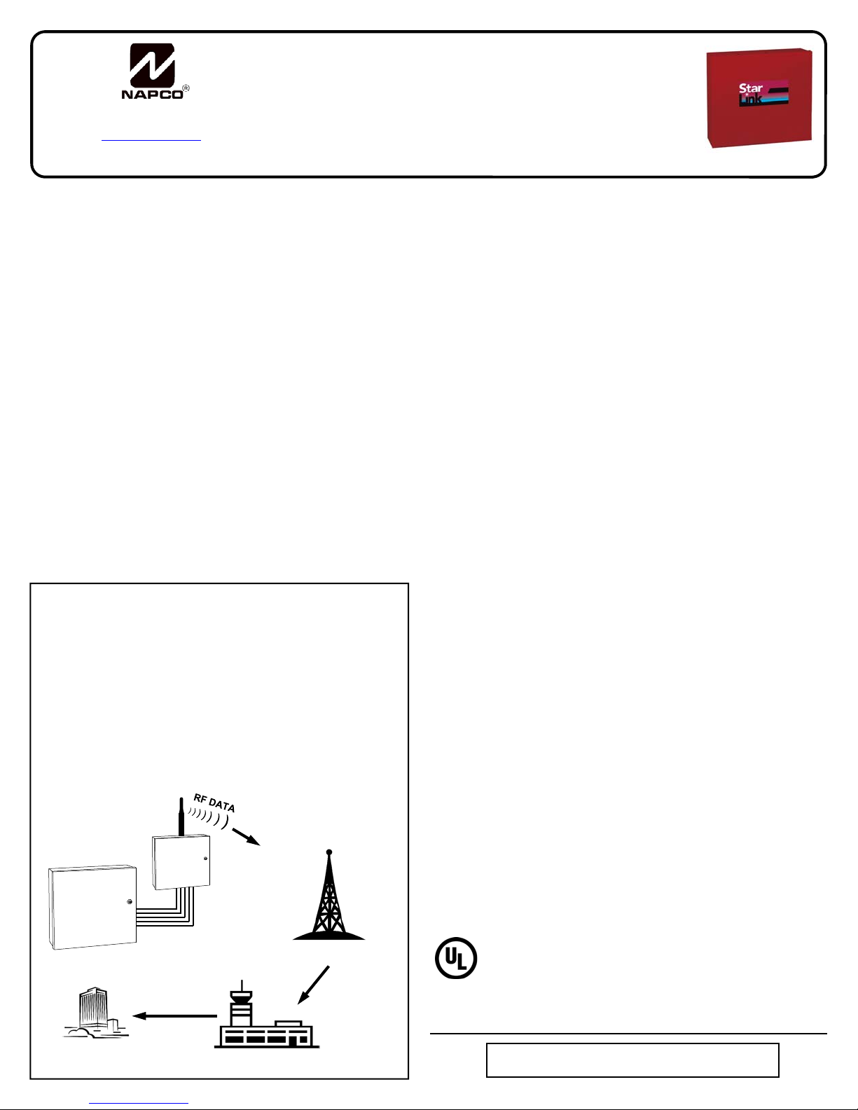
STARLINK RADIO REPORTING PATH
The diagram below shows the transmission path of a
signal from the StarLink radio to the central station.
1. Signal from a Control Panel.
2. StarLink radio receives the signal transmission
(from the TIP an RING wires); sends RF signal
through the network operator.
3. Network Operator, part of the vendor system, a
section of the cellular spectrum.
4. SLE Control Center, receiv es and routes data.
5. Central Station.
( ( ( ( ( ( ( ( ( ( ) ) ) ) ) ) ) ) ) )
StarLink
Radio
armed condition, any loss of communication must be
treated as a Burglary Alarm at the Central Station.
The following models are available:
SLE-LTEV-CFB-PS: Commercial / Residential Fire and
Burglary Radio in red metal housing with SLE-ULPS-R
power supply and 16.5V / 20VA transformer mounted
inside housing
SLE-LTEV-CB-TF: Commercial / Residential Burglary
and Residential Fire Radio in white metal housing with
SLE-ULPS-R power supply and TRF12/T123 plug-in
16.5V / 20VA transformer
SLE-LTEV-CFB: Commercial / Residential Fire and Bur-
glary in red metal housing. Powered directly from control
panel (no power supply, no transformer, rated 12/24VDC
input)
SLE-LTEV-CB: Commercial / Residential Burglary and
Residential Fire Radio in white metal housing. Powered
directly from control panel (no power supply, no transformer)
The following features are included with models that include
a SLE-ULPS-R power supply:
Power limited output to the StarLink radio PC board 12V
input terminals
Battery connection red and black flying leads
Monitored battery charging and Active battery test circuits
StarLink radio trouble input (from StarLink radio PC board
PGM1 terminal to de tect StarLink radio trouble)
Requires a sealed lead acid min 4AH / max 7AH battery
for minimum 24-hour standby time (max charge current
200mA).
Trouble relay output (C, N/O and N/C termi nals) to w i re
to a panel zone dedicated to "LTE Trouble" (dry contacts). Remove jumper "J2" to isolate common from
ground
Green AC ON LED visible from the exterior housing
Yellow TROUBLE LED on PC board. Flashes signify:
One flash: AC fail / brownout (2 hour delay)
Two flashes: Low battery
Three flashes: Charging circuit trouble
Four flashes: StarLink radio trouble
The housing-mounted transformer (when provided) is mount-
(2)
Control
Panel
CENTRAL
STATION
StarLink
™
SLE-LTE Commercial Series Alarm Communicators -- Installation Instructions 1
(1)
(5)
UL Classified StarLink Network
Operations Center
(3)
Network
Operator
(4)
AGENCY LISTINGS
UL 864 Standard For Control Units and Accessories For
Fire Alarm Systems, 10th Editio n
UL 1610 Standard For Central-Station Burglar-Ala rm Units
UL 985 Standard For Household Fi re Wa rning Sy stem Unit s
UL 1023 Standard For Household Burglar-Alarm System
Units
LTEV models are Verizon® Network Certified
Page 2

ed inside its own housing compartment with a replaceable
UL Listed .5A fast blow primary fuse. 120VAC connections
are to be made by a licensed electrician using suitable connectors, in accordance with N.E.C. and local code requirements.
ADDITIONAL COMPONENTS
In addition to the models listed above, the following sub-
assemblies are available:
SLE-ULPS-R - Power Supply. Required for installations
where the control panel cannot provide the 71mA of
Auxiliary power required to operate the StarLink radio.
Uses a standard 4AH / 12V minimum (7AH maximum)
rechargeable battery to provide radio standby power.
Requires connection to either the model NAPCO
TRF12/T123 (16.5V / 20VA) external plug-in transformer
or the chassis-mounted 16.5VAC / 20VA transformer
affixed inside the housing (see wiring diagrams further in
this manual). Note: For models without the SLE-ULPSR, connect the radio terminals 1 and 2 to the control
panel Aux Power terminals (observing polarity).
SLE-DLCBL - Download Cable, 6 feet
SLE-ANTEXT30 - Extended antenna with 30 feet of cable
SLE-ANTEXT50 - Extended antenna with 50 feet of cable
SLE-ANTEXT75 - Extended antenna with 75 feet of cable
(Any suitable external cellular antenna is permitted by
UL). Always follow the manufacturer's installation instructions. Note: Antennas are not Listed by UL. For
LTE radios where an External Antenna needs to be installed outside of the room in which the radio is installed
(maximum 30 meters (98 feet) in Residential applications), please use RF Transmitter Board
9SLELTEEXAPSLD available from our Customer Service Department, if not provided. The
9SLELTEEXAPSLD is identified by "two red dots" located on the lower right corner of the board. See WI2239
included with the 9SLELTEEXAPSLD for the simple installation procedure.
GEM-Tamperkit - Tamper switches and screws to protect
metal housing (see page 18).
SPECIFICATIONS
The following specifications apply to all StarLink radio mod-
els unless otherwise stated:
Electrical Ratings for 120VAC, 60Hz
For Models with Power Supply
Input Voltage: 120VAC nominal
Input Current: 150mA maximum
Maximum Charging Current: 200mA
Electrical Ratings for +12V
For Models without Power Supply*
Input Voltage: 10-15VDC (power-limited output from
Listed control panel). Note: Model SLE-LTEV-CFB is
rated 10-25VDC input.
Input Current for SLE-LTEV-CB: 10V = 90mA , 12V =
71mA, 15V = 63mA, with peak RF transmission current
of 200mA.
Input Current for SLE-LTEV-CFB: 10V = 90m A , 12V =
71mA, 25V = 68mA, with peak RF transmission current
of 200mA.
Electrical Ratings for the IN 1 Burg/Fire Input:
Input Voltage: 9-15VDC. Note: Model SLE-LTEV-CFB
is rated 9-25VDC input.
Maximum Input Current: Up to 2mA from FACP NAC
circuit
Electrical Ratings for IN 2 and IN 3:
Maximum Loop Voltage: 15VDC. Note: Model SLE-
LTEV-CFB is rated max 25VDC input.
Maximum Loop Current: 1.2mA
End of Line Resistor (EOLR) Value: 10K (2 req'd)
Electrical Ratings for 3 PGM Outputs:
Open Collector Outputs: Maximum Voltage 3V when
active; 15V maximum when not active. Note: Model
SLE-LTEV-CFB is rated max 25VDC output.
Maximum PGM Sink Current: 50mA (up to 15VDC),
25mA (15.1VDC - 25VDC)
Physical (W x H x D)
Metal Housing: 11½ x 9½ x 3½" (29.2 x 24.1 x 8.9cm)
Mounting: Metal housing includes two keyhole slots for
wall mounting (see measurements on page 7)
Environmental
Operating Temperature: 0°C - 49°C (32°F - 120°F)
Humidity: Maximum 93% Non-Condensing
Indoor / dry location use only
NOTICE TO AUTHORITIES HAVING JURISDICTION, USERS, INSTALLERS,
DEALERS, AND OTHER AFFECTED PARTIES
FIRE PROGRAMMING OPTION
Unattended Remote Downloading No Enable / Disable
IN2 and IN3 Unsupervised Yes Supervised / Unsupervised
7 Day Supervision, Radio to NOC No
*For Commercial Fire installations, a UL Listed Fire Alarm regulated power supply or FACP regulated auxiliary output is required.
2 StarLink
PERMITTED IN
UL864? (Y/N)
AVAILABLE SETTINGS REQUIRED UL 864 SETTINGS
Disabled (Jumper 1 installed). Also required for Commercial / Burgla-
ry installations. Note: See page 7 "Configuration Download / Firm-
ware Updates" for jumper instructions.
Unsupervised using conduit within 20 feet of FACP (default). If not
using conduit, install Jumpers 4 and 5 and EOL Resistors (see pages
3 and 4).
200 seconds, 5 minutes,
60 minutes, 7 days
™
SLE-LTE Commercial Series Alarm Communicators -- Installation Instructions
200 seconds, 5 minutes, 60 minutes
Page 3

TERMINAL DESCRIPTIONS
Configure all inputs and outputs using the Management Center screen (located at www.napconoc.com).
Located at the bottom of the StarLink radio PC board, the
17 terminals are described as follows:
TB1: PWR (+12V) Note: Model SLE-LTEV-CFB is rat-
ed 12/24VDC input.
(Refer to section "STEP 4: APPLY POWER")
TB2: PWR GND (–)
(Refer to section "STEP 4: APPLY POWER")
TB3: PGM1 (–): Open collector output. PGM1 is nor-
mally on (active low). When it is triggered (for ex-
ample, a trouble is detected) it becomes open col-
lector/high. To have a zone dedicated to an Star-
Link radio trouble, insert one side of the end of line
resistor into this PGM1 terminal, and wire the other
side of the resistor to the positive terminal of the
zone.
TB4: PGM2 (–): Open collector output. This output is
defaulted as "Fail to Communicate", and is normally
open collector/high. When a report fails to com-
municate anywhere in the communications path, the
output is active low.
TB5: PGM3 (–): Open collector output. This output is
defaulted as "Telephone Line Cut". When the tele-
phone line voltage is correct, the output is open col-
lector/high; when the telephone line voltage is too
low, the output is active low.
TB6: IN 1: Active high input for wiring to the panel
bell output. When this input detects a pulsing tem-
poral 3 high, it sends a Fire alarm; a pulsing tem-
poral 4 (CO Alarm), a CO alarm is sent. When
used, these conductors must be run in conduit (max
20 feet for Commercial Fire, and 3 feet for Residen-
tial Fire). Do not use for Burglary applications.
TB7: IN 2: See TB9, below.
TB8: GND: Common ground terminal.
TB9: IN 3: Both terminals IN 2 and IN 3 by default are
supervised end-of-line resistor inputs that can be
triggered with N/O or N/C relay contacts. Wire the
common ground terminal GND (terminal TB8) to the
relay common. In Burglary applications, when used
as arm/disarm status input, a low indicates "armed"
and a high indicates "disarmed". For these inputs to
report to a central station, the radio must be configured with the central station telephone number and
correct reporting formats and codes. See table on
page 17 for more information.
TB10: TIP: See TB11, below.
TB11: RING: Terminals TIP and RING: Wh en used f o r
backup reporting, the house Tip and Ring telephone
wires must be routed from the outside to these terminals. Under normal back up conditions, these
terminals are internally wired to the PANEL TIP and
PANEL RING terminals, allowing all transmissions
to the central station to be monitored. These wires
are monitored for voltage such that if voltage falls
below 1.5V, a Telco Line Fault trouble is detected,
and the StarLink radio applies telephone line voltage to the control panel Tip and Ring DACT interconnect to the radio allowing it to receive and transmit any alarms sent by the panel.
TB12: PANEL RING: See wiring diagrams.
TB13: PANEL TIP: See wiring diagrams.
Note: TB14-TB17 no connections permitted by UL.
TB14: RTS (R): See TB17 below.
TB15: PANEL TX (B): See TB17 below.
TB16: PANEL RX (G): See TB17 below.
TB17: CTS (Y): No connections permitted.
LED DESCRIPTIONS
The PC board contains several LED's, as follows:
GREEN RF SIGNAL STRENGTH LED
Labeled "D3", this LED is located at the lower right corner
of the PC board.
Every 30 seconds, the StarLink radio receiver section
turns on and listens to the cell tower. Depending on the
Supervised Fire / Burg Input
8 7 9
Radio GND
(TB8)
(Radio)
(Alarm Panel)
10K
10K
C C N/O
TBL*
The EOLR must be installed and located within the control panel housing.
*Reverse polarity / energized state.
StarLink
™
SLE-LTE Commercial Series Alarm Communicators -- Installation Instructions 3
Alarm
-or-
To StarLink
Terminals
IN2 (TB7)
-or-
IN3 (TB9)
N/O
N/C
Supervised Arm / Disarm Input
To StarLink
-or-
8 7 9
Radio GND
(TB8)
(Radio)
(Alarm Panel)
10K
10K
C
Open = Disarmed
Closed = Armed
The EOLR must be installed and located within the control panel housing.
Terminals
IN2 (TB7)
-or-
IN3 (TB9)
Page 4

RED DIAGNOSTIC LED (Labeled "D7")
YELLOW OPERATIONAL STATUS LED (Labeled "D4")
GREEN RF SIGNAL STRENGTH LED (Labeled "D3")
RED TROUBLE LED (Labeled "D5")
D4 D3 D5
LED LOCATIONS
signal strength detected, it will blink the Signal Strength
LED from 1 to 8 times, providing a signal strength indicator that is updated constantly and is always displayed.
Refer to Coverage Table below.
Green LED Operation
Signal strength (as received by the radio) is displayed by
this LED blinking 1 to 8 times at a constant rate (with a
short delay between blink cycles). Acceptable power
level is greater than or equal to -91dBm (minimum 4
blinks at the mounting location).
LED Blinks 8 7 6 5 4 3 2 1
GREEN RF SIGNAL STRENGTH LED
RADIO RECEIVER COVERAGE TABLE
Power
(dBm)
-55 -65 -75 -85 -91 -95 -99 -105
YELLOW OPERATIONAL STATUS LED
Labeled "D4", this LED is located at the bottom right of
the PC board. Operation is as follows:
Normal Standby Condition:
Blinks on momentarily every 10 seconds: Unit is in
standby waiting for an alarm to report.
Processing Alarm Conditions:
When processing an alarm, this LED will blink variably
during each part of the process (dialing, handshaking,
data transmission, etc.).
RED TROUBLE LED
Labeled "D5", this LED is located at the bottom right of
the PC board. Operation is as follows:
1 Blink: Low Aux Power input voltage
2 Blinks: Battery trouble
3 Blinks: Alarm report Failed to Communicate
4 Blinks: RF trouble (antenna connection or cellu-
lar registration)
5 Blinks: Network trouble (signal unable to reach
the SLE Control Center)
6 Blinks: Unit disabled (r eporting or control panel
downloading not allowed)
7 Blinks: Unit was shutdown and has no function-
ality; requires a restart (full power down and full power
up sequence) to restore operation
8 Blinks: Telco Line Cut (this is not the DACT inter-
connect to the radio)
RED DIAGNOSTIC LED
Labeled "D7", this LED is located in the middle of the PC
board. One blink indicates a weak or non-existent signal
from the network (green LED is off). If this red LED is
blinking in any other manner, please contact technical
support.
SUPPLYING POWER
Control panels can provide power through their Auxiliary
Power terminals if the available standby current is reduced by
71mA. When there is insufficient standby current due to the
application (such as when 24-hour standby time is required
for Fire or CO), the SLE-ULPS-R Charger Module accessory
must be used to charge an additional battery and to supply
the power for the StarLink radio. See WI2131.
JUMPER DESCRIPTIONS
Jumper block labeled "X5"; from top to bottom, as detailed in
the following table. Note: Contact ID is always available in
response to a Contact ID handshake.
Tech on site must temporarily
remove to download
4/2 with Checksum Pulse Format 2 4/2 Pulse Format
Supervised inputs. EOLR(s) re-
quired, see page 3
The StarLink SLE-LTE Series radios are compatible with
any Listed alarm control unit DACT communicating contact
ID or any 4+2 pulse format (4/2 Pulse Dialing formats such
as Ademco Slow, Radionics Slow, Silent Knight Fast, Radionics Fast and Universal High Speed, with 10pps, 20pps,
and 40pps with and without checksum, either 1400Hz or
2300Hz handshake / kissoff).
The StarLink SLE-LTE Series radios and NOC are compati-
ble with the Listed Ademco model 685 with model 685-8 line
card DACR or any Listed compatible DACR with any 4+2
pulse or contact ID format which is specified in the Installation Instructions for the interconnected DACT / Alarm Control Unit.
Refer to WI2140 (available on the NOC) for selecting the
required handshake / kissoff frequency in the NOC
(www.NapcoNOC.com) setup screens (as required by the
control panel).
Jumper Block "X5" Options
Jumper block labeled "X5" contains 5 jumper terminals; from top
(labeled "1") to bottom (labeled "5") as follows:
Jumper ON
Backup Mode 3 Primary Mode
Jumper
Number
1
4 and 5
Jumper OFF
Not permitted by UL 864 and
UL 1610
Not permitted by UL 864 and
UL 1610 (UL 864 permits use of
conduit within 20 feet of FACP in
lieu of Supervision)
PRIMARY AND BACK-UP REPORTING
The StarLink radio can function as a primary wireless com-
municator, in cases where there are no telephone lines present, when connected directly to the control panel Telco
4 StarLink
™
SLE-LTE Commercial Series Alarm Communicators -- Installation Instructions
Page 5

terminals. For primary reporting, do NOT install jumper 3
in terminal block "X5". The StarLink radio can also function as a backup to the existing telephone lines (install
jumper 3 in terminal block "X5"). When used as a back up
communicator and when it senses telephone line trouble,
the StarLink radio automatically switches the communication channel from the telephone line to the network.
NETWORK COVERAGE
The StarLink radio constantly supervises the network cov-
erage. When the StarLink radio is configured for primary
reporting, and the StarLink radio detects a loss in network
coverage, the StarLink radio must be configured to prompt
the control panel to announce a Telco Line Cut failure trouble using the Management Center screen (located at
www.NapcoNoc.com). Note: This Telco Line Cut failure
trouble will NOT activate when the StarLink radio is configured for backup reporting.
INSTALLATION STEPS
STEP 1: ACCOUNT REGISTRATION
Create a new account and register specific StarLink radio
modules at www.NapcoComNet.com. Accounts and modules registered via the Internet are enabled for activation
within 24 hours.
STEP 2: SELECT A MOUNTING LOCATION
The mounting location should be indoors within the protected area and selected based on RF performance. It is
HIGHLY recommended that the installer carefully adhere to
the following recommendations BEFORE any wires are installed.
Generally, high locations are best. DO NOT mount radio
in basements or below grade as unpredictable performance may result.
DO NOT mount the radio in non-climate controlled envi-
ronments (i.e. attics may become extremely hot in summer, garages may become extremely cold in winter).
Avoid mounting locations within 3 feet of AC power lines,
fluorescent light fixtures, or large metal objects (air conditioners, metal garage doors, etc.) as these locations
have been shown to have a detrimental effect on signal
strength.
A fair amount of care may be required to mount the Star-
Link radio so as to achieve an optimal RF path. The
installer should spend as much time as needed to obtain
the highest signal level possible.
For Commercial Burglary installations, install in accord-
ance with UL 681, Standard for Installation and Classification of Burglary and Holdup Alarm Systems. Installation shall also be in accordance with UL 827, Standard
for Central-Station Alarm Services, and UL 1641, Standard for Installation and Classification of Residential Burglar Alarm Systems
a. Before applying power, be sure to connect the
antennas. Temporarily connect power to the StarLink radio from a fully charged 12V (4AH minimum)
battery. DO NOT mount the radio at this time. Press
Tamper switch to send a signal.
b. Position the unit in the desired mounting location, with
antenna oriented vertically. The signal strength is
displayed by the Green "Signal Strength LED" labeled
StarLink
™
SLE-LTE Commercial Series Alarm Communicators -- Installation Instructions 5
"D3" (located at the lower right corner of the PC
board). The radio tower signal strength may fluctuate
from day to day, therefore it is best to try to find a
mounting location where the LED provides a mini-
mum of 4 blinks.
c. Once a location has been selected based on signal
coverage, permanently secure the unit using #8
screws (not supplied) in the two mounting holes.
WARNING: To ensure user safety and to satisfy FCC
RF exposure requirements, this unit must be installed so
that a minimum separation distance of 60cm (24") is always maintained between the antenna of the transmitting
device and nearby persons.
STEP 3: WIRING (PRIMARY AND BACKUP MODES)
22-gauge wire may be used if mounted up to 50 feet from
the control panel, and 18-gauge wire should be used for up
to 100 feet. Reference the wiring diagrams further in this
manual. See the section CONTROL PANEL PROGRAM-
MING further in this manual.
For Primary Mode:
Remove jumper #3 in jumper block labeled "X5". The wiring between the control panel and the StarLink radio is over
five (5) wires, as follows:
TB1: PWR (+12V) Note: Model SLE-LTEV-CFB is
rated 12/24VDC input.
TB2: PWR GND (–)
TB13: PANEL TIP
TB12: PANEL RING
TB3: PGM1 (–). Normally low output wired to the
(+) of a zone dedicated to monitoring the radio status.
See page 12 for GEMC-F8ZCPIM wiring. Should be
programmed on Napco control panels as Day Zone, but
be programmed to sound locally and NOT activate the
bell. Note : See steps "a" and "b", below.
For Backup Mode:
Install jumper #3 in jumper block labeled "X5". The wiring
between the control panel and the StarLink radio is over
seven (7) wires, as follows:
TB1: PWR (+12 or 12/24V)
TB2: PWR GND (–)
TB10: TIP
TB11: RING
TB13: PANEL TIP
TB12: PANEL RING
TB3: PGM1 (–). Normally low output wired to the
(+) of a zone dedicated to monitoring the radio status
(see page 12 for GEMC-F8ZCPIM wiring). Should be
programmed on Napco panels as Day Zone, but be
programmed to sound locally and NOT activate the bell.
a. Without applying power (voltage), connect to screw
terminals TB1 (+12 or 12/24V) and TB2 (–). If t h e
control panel Aux. Output cannot supply the necessary current, then you must use the SLE-ULPS-R
Power Supply accessory with additional battery (see
WI2131). For wir i ng con n ec ti ons , se e t he wi r ing d iagrams further in this manual.
b. Referencing the correct wiring diagram for the ap-
propriate control panel (wiring diagrams are located
further in this manual), connect the "TELCO" control
Page 6

panel terminals TIP and RING (DACT interconnect
wiring to the radio). Do NOT connect the StarLink
radio terminals TB10-13 to house telephone lines
(RJ31X modular plug wires, etc.).
Wiring Methods
Strip wire carefully to avoid exposed conductors after
installation, etc.
Use UL Listed wire, ensuring that all conductors are to be
insulated for the maximum voltage of any conductor in
the enclosure
All wiring methods must be performed in accordance with
NFPA 70, Articles 725, and 800
STEP 4: APPLY POWER
Attach primary (top left) antenna before applying
power !
The StarLink radio requires +12 or 12/24VDC. It draws
less than 71mA during standby, and almost 200mA dur-
ing transmissions (for less than 1 second).
STEP 5: SIGNAL VERIFICATION
Verify Online: To veri fy t hat the signals have been
received by the StarLink radio LTE Network online, go to
www.napconoc.com, log in with your Username and
Password, enter your Company ID number and the Star-
Link LTE Radio Number, then click Signal Log.
IMPORTANT: Verify that the signals transmitted by the
StarLink radio have been properly received by your central
station before leaving the premises.
NAPCO CONTROL PANEL PROGRAMMING
To program the central station receiver reporting format,
use PCD-Windows Quickloader download software. Open
the Digital Communications screen, Central Station Receiv-
ers tab, as shown in the following image. A "Point
ID" (also called "Contact ID") receiver format programming
example is shown:
The radio can transmit to any central station capable of re-
ceiving SIA Contact ID via DACR technology or the DSC
Sur-Gard System II or Sur-Gard System V central station
receivers via TCP/IP.
STARLINK RADIO RELATED EVENT
REPORT CODES
EVENT AREA
IN 1 Fire
IN 2 Panic
IN 3 Trouble
Low Battery/Voltage
Tamper Trouble
Line Cut
Reboot
IN 1 CO (Carbon Monoxide)
Panic Alarm*
Holdup Alarm*
Medical Alarm*
24 hour Aux. Alarm*
24 hour Aux. Restore*
Burg Perimeter Alarm*
Burg Interior Alarm*
Keypad Holdup Alarm (ambush)*
Keypad Panic Alarm*
Keypad Emergency Alarm*
Opening*
Closing*
A.C. Trouble*
Tel 1 Fail*
*Not generated by the StarLink radio.
Note: A receiver reporting format must be entered for
each telephone number used, but each telephone number
may be assigned a different format.
CAUTION: The installer should always be certain an
area code is programmed into the control panel.
Optional: If you wish the StarLink radio to report a code
and zone number (Contact ID by default) to the central station in response to a triggered input event, see the table on
(Contact ID by default)
CONTACT ID
CODE ZONE #
0 E110 990 1A
0 E120 992 22
0 E300 993 F3
0 E302 994 F4
0 E341 995 F5
0 E352 996 F6
0 E625 997 F7
0 E162 998 18
E123
E122
E100
E150
R150
E131
E132
E121
E123
E140
E401
R401
E301
E351
PULSE
4/2
SIGNALS ORIGINATED AT THE NOC
NOC Originated
Alarms
Supervisory Fail E356 A00 Zn000
Press to Send
Test Signal
Press to Send
Radio Test
6 StarLink
Contact ID
Event Data
Sent
E601 A00 Zn000
Not Applicable
Nothing sent to
CS receiver
Automatically by NOC if fail to receive any signal
from StarLink radio within Supervisory Timeout
duration.
Manually by dealer from the Management Center
Signal Log screen (located at
www.napconoc.com). Sends test into CS receiv-
er.
Manually by dealer from the Management Center
Checkins screen (located at
www.napconoc.com). Sends a command to the
StarLink radio to force a check-in to the NOC.
Initiated By Comments
For Auto Enroll, uses captured telephone number,
Sub ID and format. For Dealer Programmed, uses
entered telephone number, Sub ID and format.
Same comment as above.
----
™
SLE-LTE Commercial Series Alarm Communicators -- Installation Instructions
Page 7

the previous page.
Note: These event codes and zone numbers can be
changed from the Management Center screen (located at
www.napconoc.com).
Upon alarm, the NOC can optionally send an SMS message to a third party that includes the appropriate Contact
ID alarm code, including the zone or user number, if applicable. The "STARLINK RADIO RELATED EVENT RE-
PORT CODES" table also includes the most common Contact ID alarm codes.
Programming StarLink Radio Troubles
It is required that if a StarLink radio or control panel trou-
ble is detected, that it is reported to the central station.
When the StarLink radio detects and sends a trouble to
the control panel, the control panel must be programmed
to annunciate this trouble. The radio can detect multiple
troubles as indicated by the "Red Trouble LED" ("D5").
For these troubles to be annunciated at the panel, there
are several methods, some of them are configurable at the
Management Center screen (www.napconoc.com):
Wire the radio PGM1 output to a dedicated control panel
zone (input) to annunciate the trouble (activate a trouble
sounder) when an open is detected. The radio must
also report this trouble to the central station. With Napco control panels, program a dedicated zone for Day
Zone, Mini-sounder on Alarm and No bell on Alarm.
Wire the zone as indicated in the wiring diagrams further
in this manual.
For models with the SLE-ULPS-R Power Supply, wire
this Power Supply trouble output relay to the two terminals of the control panel zone dedicated to the trouble.
With the GEMC Commercial Fire control panels, use the
dry contacts of the Power Supply relay by removing the
jumper and using the contacts of the Power Supply relay
(Common and N/O) in series with a 2.2k EOLR.
For radio models without the SLE-ULPS-R Power Sup-
ply (powered by the control panel Aux Power terminals),
wire the radio directly to the PGM1 output of the control
panel (program the radio to report all troubles on
PGM1). Alternatively, you can use the GEMC-F8ZCPIM
module to detect a trouble on the zone by use of a PGM
output of the radio. See special wiring instructions for
use of the GEMC-F8ZCPIM zones.
You can also wire to the positive terminal of the dedicat-
ed zone on a GEMC-EZM8. Thus when a radio trouble
is detected, the radio PGM activates the control panel
zone, and the panel generates a trouble that is sent to
the central station.
All installations also require wiring an output from the
control panel, as follows: With Gemini C-Series
(GEMC) control panels, we recommend using the Fire
Aux Relay. Program the Fire Aux Relay to activate as a
trouble relay. Wire this relay to the StarLink module IN2
terminal.
Note: We recommend using the text " LTE Trouble"
as the Zone Description.
StarLink Radio Supervision
If the two Telco wires (DACT interconnect wiring to the
radio) between the StarLink radio and the control panel
are cut or otherwise disconnected, the control panel must
detect and generate a local trouble indication. The control
panel must trigger an output to activate the StarLink radio
to report this line cut fault to the central station. Program
the control panel for telephone supervision. Program the
StarLink radio using the Management Center "Advanced
Features" screen (at www.napconoc.com) to enable the
Line Cut feature on all troubles (therefore a dedicated zone
is not required). Note: Some control panels may require a
different duration than the default time of 3 minutes.
Supervision Time Schedule Considerations
If a status change (alarm trouble, etc.) is transmitted, the
radio supervision timer is restarted.
For example, if a status change is sent, the next regular
supervision transmission will occur at the interval determined by your rate plan.
Configuration Download / Firmware Updates
Technician on site required.
For Commercial Installations a technician is required to be
on site during any reprogramming of the radio or control
panel and must perform / re-perform acceptance testing.
To perform a download or update the radio firmware,
jumper 1 must be removed. UL requires that the jumper
be replaced after the download is complete. Failure to
replace the jumper would allow downloads to the radio
without a technician on-site.
For Residential installations jumper 1 may be removed to
permit uploading and downloading without a technician on
site, however, the dealer is responsible for ensuring the
system is operating correctly after any downloads or
changes to the system.
Cover Tamper
The SLE-LTE series radios in the metal housings may op-
tionally have front and rear tamper switches installed
(GEM-Tamperkit) and wired to the control panel (see page
18). Note: The tamper switch on the radio PC board is
not used in this housing (but continues to function if
pressed).
11-1/2"
10-1/8"
9-1/2"
9-21/64"
Red and White Metal Housing Dimensions (inches)
StarLink
™
SLE-LTE Commercial Series Alarm Communicators -- Installation Instructions 7
Page 8

(Commercial Fire and Commercial Burglary)
SLELTEV-CFB-PS
Wiring Diagram
(To
control
panel*)
BLK
.5A
Fuse
SLELTEV-CFB-PS
PC Board
All connections are power limited except AC
Mains, Telco and battery terminals
Terminals 14-17: No connections permitted .
PANEL
(–)
PGM1 PGM2 PGM3 IN3 RING TIP
+V
IN1
6 7 8 15 14 13 12 11 9 10 2* 3 4 5 1*
IN2*
GND
RING
Note: Connect IN2 to a
panel output used for
identifying Telco line cut (this
is the DACT interconnect
wiring to the radio).
PANEL
RTS
PANEL
PANEL
TIP
(R)
RX (G)
TX (B)
16.5VAC
Class 2
CTS
17 16
Yellow
Trouble
LED
Green AC
ON LED
Power Supply
(SLE-ULPS-R)
Relay contacts rated
max 30VDC,
0.5A
12VDC
output is
Y
power limited
AC IN
+ 12V –
N/O
COM
8 9 10
N/C
IN1
J2
+ BAT –
RED BLK
6 7 2 3 4 5 1
Red (+)
Black (‒)
Battery
Remove shunt J2 to isolate relay
EOLR*
Note: Maintain
minimum 1/4"
separation of
battery leads from
all other wiring.
common from ground (i.e. jump-
er on = wet; off = dry contact)
(Earth Ground)
Chassis Mounted 16.5VAC / 20VA Transformer
*Notes:
Connect the StarLink radio to the control panel output for Telco Trouble (this is the DACT interconnect wiring to the
radio). Remember to program the StarLink communicator module to report this IN2 Telco Trouble and for line cut
(EOLR) to the central station (options 1 or 4 on page 17). In addition, always add an EOLR at the control panel Telco
Trouble Output (Fire Aux Relay for the GEMC control panels).
Use EOLR value as specified by the control panel installation instructions.
IN1 not supervised. IN2 and IN3 are supervised.
Licensed electrician required to wire the 120VAC connections to the transformer in accordance with N.E.C. and local
code requirements.
Route 1 20VAC only through the transformer compartment knockouts.
Keep all non-power limited wiring separate from all power-limited wiring inside the housing by 1/4". In addition, maintain
a minimum 1/4" separation of all primary wiring in the transformer compartment from the yellow secondary wires of the
transformer.
Remove shunt J2 to isolate relay common from ground (i.e. jumper on = wet (circuit common); off = dry contact). When
wet, configuration is used; the power should be derived from the alarm control panel.
StarLink module must be configured to trigger PGM1 on any trouble.
PGM1 of the StarLink module must be wired to the trouble input (terminal 5) of the power supply.
The Power Supply Trouble Output must be wired to a control panel zone dedicated to a LTE trouble; see control panel
programming instructions and program to Report Alarm / Alarm Restore / Trouble / Trouble Restore.
8 StarLink
Note: Maintain minimum 1/4" separation
of all wiring in this compartment from the
yellow wires of the transformer.
™
SLE-LTE Commercial Series Alarm Communicators -- Installation Instructions
Page 9

(Commercial Burglary)
SLE-LTEV-CB-TF
Wiring Diagram
(To
control
panel*)
TRF12/T123
SLE-LTEV-CB-TF
PC Board
Yellow
Trouble
LED
Green AC
ON LED
All connections are power limited except
AC Mains, Telco and battery terminals
Power Supply
(SLE-ULPS-R)
Terminals 14-17: No connections permitted.
Note: Connect IN2 to a
panel output used for
identifying Telco line cut (this
is the DACT interconnect
wiring to the radio).
PANEL
PANEL
RTS
PANEL
(–)
PGM1 PGM2 PGM3 IN3 RING TIP
+V
IN1
IN2*
GND
RING
PANEL
TIP
(R)
TX (B)
6 7 8 15 14 13 12 11 9 10 2* 3 4 5 1*
Transformer
16.5V / 20VA
16.5VAC
Class 2
RX (G)
CTS
17 16
Y
Relay contacts rated
max 30VDC,
0.5A
12VDC
output is
power limited
AC IN
+ 12V –
N/O
COM
8 9 10
IN1
N/C
J2
+ BAT –
RED BLK
6 7 2 3 4 5 1
Red (+)
Black (‒)
Battery
Remove shunt J2 to isolate relay
common from ground (i.e. jump-
EOLR*
Note: Maintain
minimum 1/4"
separation of
battery leads from
all other wiring.
er on = wet; off = dry contact)
*Notes:
Connect the StarLink radio t o the control panel output for Telco Trouble (this is the DACT interconnect wiring to
the radio). Remember to program the StarLink communicator module to report this IN2 Telco Trouble and for line
cut (EOLR) to the central station (options 1 or 4 on page 17). In addition, always add an EOLR at the control
panel Telco Trouble Output (Fire Aux Relay for the GEMC control panels).
Use EOLR value as specified by the control panel installation instructions.
IN1 not supervised. IN2 and IN3 are supervised.
Keep all non-power limited wiring separate from all power-limited wiring inside the housing by 1/4".
Remove shunt J2 to isolate relay common f rom ground (i.e. jumper on = wet (circuit common); off = dry contact).
When wet, configuration is used; the power should be derived from the alarm control panel.
StarLink module must be configured to trigger PGM1 on any trouble.
PGM1 of the StarLink module must be wired to the trouble input (terminal 5) of the power supply.
The Po wer Supply Trouble Output must be wired to a control panel zone dedicated to a LTE trou ble; see control
panel programming instructions and program to Report Alarm / Alarm Restore / Trouble / Trouble Restore.
StarLink
™
SLE-LTE Commercial Series Alarm Communicators -- Installation Instructions 9
Page 10

Transformer
Wiring Diagram for PRIMARY Reporting Configuration
Generic Control Panels
(Use when telephone line is NOT available)
(CONTROL PANEL HOUSING)
CONTROL PANEL PC BOARD
12VDC
TBL INPUT
GND
AUX POWER
Optional: When Power
Supply SLE-ULPS-R is not
used, connect Panel Aux
Power to StarLink terminals
1 and 2 (observing polarity)
(–) (+)
(–) (+)
(RING)
(TIP)
Wire to dedicated zone on the control
panel for Supervision when the Power
Supply board (SLE-ULPS-R) is n ot used.
6 7 8 15 14 13 12 11 9 10 2* 3 4 5 1*
+V
PGM1 PGM2 PGM3 IN1 IN2 GND IN3 RING TIP
(–)
PANEL
RING (+)
StarLink Radio Terminals
SLE-LTEV-CB-TF PC Board: All connections
are power limited except AC Mains, Telco and
battery terminals. Terminals 14-17: No connec-
(STARLINK RADIO HOUSING)
tions permitted.
*Refer to section "SUPPLYING POWER".
10 StarLink
N/O
Note: Connect IN2 to a
panel output used for
identifying Telco line cut (this
is the DACT interconnect
wiring to the radio).
COM
8 9 10
N/C
J2
17 16
PANEL
TIP (–)
PANEL
TX (B)
PANEL
RX (G)
CTS
Y
Power Supply (SLE-ULPS-R)
RTS
(R)
(optional)
Either the TRF12/T123 (16.5V /
20VA) transformer or the chas-
sis-mounted 16.5VAC / 20VA
transformer
™
SLE-LTE Commercial Series Alarm Communicators -- Installation Instructions
are not power limited
(+)
(–)
RED
BLACK
StarLink
BATTERY
Note: Battery leads
Page 11

Wiring Diagram for BACKUP Reporting Configuration
Generic Control Panels
Transformer
TO TELCO
RING TIP
RJ31X
HOME
PHONES
(CONTROL PANEL HOUSING)
CONTROL PANEL PC BOARD
TELCO
TBL
OUTPUT
10K
Telco TBL
Output
Relay
10K
GND
Optional: When Power Supply
SLE-ULPS-R is not used,
connect Panel Aux Power to
StarLink terminals 1 and 2
12VDC
AUX POWER
(observing polarity)
(–) (+)
(TELCO) (PHONE)
(RING)
(TIP)
(TIP)
YELLOW (–)
BLACK (+)
(RING)
ZONE (+)
DEDICATED
TO
SUPERVISION
*For StarLink terminals 1 and 2: May
be wired directly to
Aux Power of the
control panel when
71mA standby
current is available
+V
Note: Connect IN2 to a
panel output used for
identifying Telco line cut
(this is the DACT
interconnect wiring to the
radio).
PGM1 PGM2 PGM3 IN1 IN2 GND IN3 RING TIP
(–)
(STARLINK RADIO HOUSING)
GRN
RED
BRN
GRAY
Wire to dedicated
zone on the
control panel for
Supervision when
the Power Supply
board (SLE-
ULPS-R) is not
used.
GRN
6 7 8 15 14 13 12 11 9 10 2* 3 4 5 1*
StarLink Radio Terminals
SLE-LTEV-CB-TF PC Board: All connec-
tions are power limited except AC Mains,
Telco and battery terminals. Terminals 14-
17: No connections permitted.
RED
PANEL
RING (+)
BLACK
YELLOW
PANEL
TIP (–)
RTS
(R)
PANEL
TX (B)
17 16
PANEL
CTS
RX (G)
Y
Either the TRF12/T123
(16.5V / 20VA) transformer
or the chassis-mounted
16.5VAC / 20VA transformer
TELCO QUAD WIRE
N/O
COM
8 9 10
N/C
J2
Power Supply (SLE-ULPS-R)
(optional)
EOLR
(+)
(–)
RED
BLACK
StarLink
BATTERY
Note: Battery leads
are not power limited
*Refer to section "SUPPLYING POWER".
StarLink
™
SLE-LTE Commercial Series Alarm Communicators -- Installation Instructions 11
Page 12

Wiring Diagram for PRIMARY Reporting Configuration
GEMC-32, GEMC-96, GEMC-128 and GEMC-255 Control Panels
(Use when telephone line is NOT available)
(CONTROL PANEL HOUSING)
RJ31X
GEMC Control
Panel PC Board
RING TIP
RJ31X
RING TIP
SEE WIRING
DIAGRAM
AND WI FOR
ADDITIONAL
INFORMATION
10K
10K
MONITOR
COM
ZONE (+)
DEDICATED TO
SUPERVISION
TELCO TROUBLE OUTPUT
Special Wiring Instructions for the
GEMC-F8ZCPIM as a Monitor Zone Only
When PGM1 is wired to a GEMC-F8ZCPIM
zone, replace the 2.2k ohm EOL resistor wit h
a 560ohm 1/2 watt min EOL resistor. Connect
PGM1 to the negative terminal of the zone.
When PGM2 and/or PGM3 are wired to a
GEMC-F8ZCPIM zone, replace the 2.2k ohm
+V
EOL resistor with two 1K ohm 1/4 watt min
EOL resistors. Connect the PGM wire to the
common wire of the two resistors in series.
GEMC-F8ZCPIM
ZONE
(+)
(‒)
EOLR 560Ω
(min 1/2W)
Radio PGM1 terminal
GEMC-F8ZCPIM
ZONE
EOLR
EOLR
1K
1K
Ω
Ω
Radio PGM2 or PGM3
terminal
Note: Connect IN2 to a
panel output used for
identifying Telco line cut (this
is the DACT interconnect
wiring to the radio).
(STARLINK RADIO HOUSING)
*Refer to section "SUPPLYING POWER".
12 StarLink
2.2K
6 7 8 15 14 13 12 11 9 10 2* 3 4 5 1*
PGM1 PGM2 PGM3 IN1 IN2 GND IN3 RING TIP
(–)
StarLink Radio Terminals
SLE-LTEV-CB-TF PC Board: All connections are power limited except AC Mains,
Telco and battery terminals. Terminals
14-17: No connections permitted.
™
SLE-LTE Commercial Series Alarm Communicators -- Installation Instructions
PANEL
RING (+)
PANEL
TIP (–)
RTS
(R)
PANEL
TX (B)
PANEL
RX (G)
17 16
CTS
Y
Page 13

Wiring Diagram for PRIMARY Reporting Configuration
GEMC-32, GEMC-96, GEMC-128 and GEMC-255 Control Panels
(Use when telephone line is NOT available)
(CONTROL PANEL HOUSING)
RJ31X
GEMC Control
Panel PC Board
RING TIP
RJ31X
RING TIP
SEE WIRING
DIAGRAM
AND WI FOR
ADDITIONAL
INFORMATION
10K
10K
COM
ZONE (+)
DEDICATED
TO SUPER-
TELCO TROUBLE OUTPUT
VISION
Note: Connect IN2
to a panel output used
for identifying Telco
line cut (this is the
DACT interconnect
wiring to the radio).
2.2K
6 7 8 15 14 13 12 11 9 10 2* 3 4 5 1*
+V
PGM1 PGM2 PGM3 IN1 IN2 GND IN3 RING TIP
(–)
StarLink Radio Terminals
Wire to dedicated zone
on the control panel for
Supervision when the
Power Supply board
(SLE-ULPS-R) is not
used.
(STARLINK RADIO HOUSING)
*Refer to section "SUPPLYING POWER".
StarLink
™
SLE-LTE Commercial Series Alarm Communicators -- Installation Instructions 13
SLE-LTEV-CB-TF PC Board: All connections are power limited except AC
Mains, Telco and battery terminals. Ter-
minals 14-17: No connections permitted.
PANEL
RING (+)
PANEL
TIP (–)
RTS
(R)
PANEL
TX (B)
PANEL
RX (G)
17 16
CTS
Y
Either the
TRF12/T123
(16.5V / 20VA)
transformer
or the chassis-
mounted
16.5VAC /
20VA
transformer
N/O
COM
8 9 10
N/C
J2
Power Supply (SLE-ULPS-R)
(optional)
2.2K
(+)
(–)
RED
BLACK
StarLink
BATTERY
Page 14

Wiring Diagram for BACKUP Reporting Configuration
GEM-X255 / GEM-P9600 / GEM-P3200 Control Panels
(CONTROL PANEL HOUSING)
16VAC
Transformer
RING TIP
HOME
PHONES
TO TELCO
RJ31X
GRN
RED
Control Panel PC Board
1
16VAC
2
3
4
5
(Cut Jumper A)
AUX RELAY
COM
10K
6
N/C
7
N/O
8
Summary of connections:
RJ31X RED to StarLink module 10
RJ31X GREEN to StarLink module 11
RJ31X BROWN to Panel 32
RJ31X GRAY to Panel 33
Panel 30 to StarLink module 13
Panel 31 to StarLink module 12
9
10K
10
11
REMOTE
AUX PWR
PWR (─)
(+) (–)
13 14 15 16 17 18 19 20 21 22 26 27 28 29 23 24 25 33 30 31 32
TEL LINE PHONE
TIP RING TIP RING
12
GRAY
BRN
BLACK
YELLOW
Optional: When Power Supply
COM
TELCO TBL
BRN
GRAY
SLE-ULPS-R is not used,
connect Panel Aux Power to
StarLink terminals 1 and 2
(observing polarity)
GRN
RED
*For StarLink module
terminals 1 and 2:
May be wired directly
to Aux Power of the
control panel when
71mA standby current is available.
Note: Connect
IN2 to a panel
output used for
identifying Telco
line cut (this is the
DACT interconnect
wiring to the radio).
GRN
RED
6 7 8 15 14 13 12 11 9 10 2* 3 4 5 1*
+V
Wire to dedicated zone on
Power Supply board (SLE-
(STARLINK RADIO HOUSING)
PGM1 PGM2 PGM3 IN1 IN2 GND IN3 RING TIP
(–)
StarLink Radio Terminals
the control panel for
Supervision when the
ULPS-R) is not used.
SLE-LTEV-CB-TF PC Board: All connections are pow-
er limited except AC Mains, Telco and battery termi-
nals. Terminals 14-17: No connections permitted.
*Refer to section "SUPPLYING POWER".
PANEL
RING (+)
14 StarLink
BLACK
ZONE (+)
RED
GRN
TELCO QUAD WIRE
YELLOW
Either the
TRF12/T123
17 16
PANEL
TIP (–)
PANEL
RTS
(R)
™
PANEL
TX (B)
RX (G)
SLE-LTE Commercial Series Alarm Communicators -- Installation Instructions
CTS
Y
(16.5V / 20VA)
transformer
or the chassis-
mounted
16.5VAC /
20VA
transformer
Power Supply (SLE-ULPS-R)
(optional)
DEDICATED
SUPERVISION
N/O
COM
8 9 10
N/C
J2
TO
2.2K
(+)
(–)
RED
BLACK
StarLink
BATTERY
Page 15

Wiring Diagram for PRIMARY Reporting Configuration
GEM-816 / GEM-P1632 / GEM-P1664 Control Panels
(Use when telephone line is NOT available)
(CONTROL PANEL HOUSING)
*Refer to section
"SUPPLYING
POWER".
+V
AUX POWER
Control Panel PC Board
(+) (–)
5
6
TELCO PHONE
TIP RING TIP RING
13 14 15 16 17 18 19 20 21 22 26 27 28 29 23 24 25
~ ~
(un-polarized)
ZONE (+)
DEDICATED TO
SUPERVISION
2.2K
6 7 8 15 14 13 12 11 9 10 2* 3 4 5 1*
PGM1 PGM2 PGM3 IN1 IN2 GND IN3 RING
(–)
StarLink Radio Terminals
TIP
PANEL
RING
(un-polarized)
Note: Connect IN2 to a
panel output used for
identifying Telco line cut (this
is the DACT interconnect
wiring to the radio).
(un-polarized)
~ ~
PANEL
TIP
RTS
(R)
PANEL
TX (B)
PANEL
RX (G)
SLE-LTEV-CB-TF PC
Board: All connections are power lim-
17 16
CTS
Y
ited except AC
Mains, Telco and
battery terminals.
Terminals 14-17: No
connections permit-
ted.
(CONTROL PANEL HOUSING)
*Refer to section
"SUPPLYING
POWER".
Wiring Diagram for PRIMARY Reporting Configuration
GEM-X255 / GEM-P9600 / GEM-P3200 Control Panels
(Use when telephone line is NOT available)
Control Panel PC Board
(Cut Jumper A)
AUX RELAY
COM
10K
10K
6
7
8
9
10
N/C
N/O
AUX POWER
(+) (–)
TEL LINE PHONE
TIP RING TIP RING
13 14 15 16 17 18 19 20 21 22 26 27 28 29 23 24 25 33 30 31 32
~
~
(un-polarized)
(un-polarized)
Note: Connect
IN2 to a panel
output used for
ZONE (+)
identifying Telco
SUPERVISION
DEDICATED TO
line cut (this is the
DACT interconnect
wiring to the radio).
2.2K
~ ~
6 7 8 15 14 13 12 11 9 10 2* 3 4 5 1*
PANEL
+V
PGM1 PGM2 PGM3 IN1 IN2 GND IN3 RING
(–)
StarLink Radio Terminals
TIP
PANEL
RING
TIP
(un-polarized)
RTS
(R)
PANEL
TX (B)
PANEL
RX (G)
SLE-LTEV-CB-TF
PC Board: All connections are power
limited except AC
Mains, Telco and
17 16
CTS
battery terminals.
Terminals 14-17:
Y
No connections
permitted.
StarLink
™
SLE-LTE Commercial Series Alarm Communicators -- Installation Instructions 15
Page 16

Wiring Diagram for BACKUP Reporting Configuration
GEM-816 / GEM-P1632 / GEM-P1664, Freedom F-64 Control Panels
16VAC
Transformer
TO TELCO
RING TIP
RJ31X
HOME
PHONES
(CONTROL PANEL HOUSING)
1
2
3
4
Optional: When Power
Supply SLE-ULPS-R is not
used, connect Panel Aux
Power to StarLink terminals
1 and 2 (observing polarity)
5
6
7
8
9
10
11
12
GRN
RED
BRN
GRAY
Control Panel PC Board
VAC
16
Summary of connections:
AUX POWER
(+)
(–)
13 14 15 16 17 18 19 20 21 22 26 27 28 29 23 24 25
RJ31X RED to StarLink module 10
RJ31X GREEN to StarLink module 11
RJ31X BROWN to Panel 28
RJ31X GRAY to Panel 29
Panel 27 to StarLink module 12
Panel 26 to StarLink module 13
TELCO PHONE
TIP RING TIP RING
GRAY
BRN
BLACK
YELLOW
ZONE (+)
DEDICATED
TO
SUPERVISION
BRN
GRAY
*For StarLink module terminals 1 and
RED
GRN
2: May be wired
directly to Aux
Power of the control panel when
71mA standby
current is available.
Wire to dedicated zone on the
control panel for Supervision
when the Power Supply board
(SLE-ULPS-R) is not used.
GRN
RED
6 7 8 15 14 13 12 11 9 10 2* 3 4 5 1*
+V
Note: Connect IN2 to
a panel output used for
identifying Telco line
cut (this is the DACT
interconnect wiring to
the radio).
(STARLINK RADIO HOUSING)
PGM1 PGM2 PGM3 IN1 IN2 GND IN3 RING TIP
(–)
StarLink Radio Terminals
SLE-LTEV-CB-TF PC Board: All connections are pow-
er limited except AC Mains, Telco and battery termi-
nals. Terminals 14-17: No connections permitted.
*Refer to section "SUPPLYING POWER".
PANEL
RING (+)
16 StarLink
BLACK
YELLOW
PANEL
TIP (–)
BRN
GRAY
YELLOW
BLACK
TELCO QUAD WIRE
2.2K
N/O
COM
8 9 10
N/C
J2
Either the
TRF12/T123
17 16
PANEL
RTS
(R)
PANEL
RX (G)
CTS
Y
TX (B)
™
SLE-LTE Commercial Series Alarm Communicators -- Installation Instructions
(16.5V /
20VA)
transformer
or the chassis-mounted
16.5VAC /
20VA
transformer
Power Supply (SLE-ULPS-R)
(optional)
(+)
RED
StarLink
BATTERY
(–)
BLACK
Page 17

Option
Application
FACP with DACT
Use IN2 or IN3 only for
trouble. Panel reports via
1
dialer capture, but Linecut
for DACT interconnection
wiring to the radio reports via
an input on radio.
FACP with DACT
Use IN1 (not supervised)
either for trouble or alarm.
2
Panel has trouble (or alarm)
relay that closes on the
condition.
FACP without DACT
Use IN2 or IN3 for both
3
Alarm and Trouble on one
input. Panel has alarm and
trouble relay outputs.
BURG with DACT
Use IN2 or IN3 for only
trouble reporting. Panel
4
reports via dialer capture but
Linecut for DACT intercon-
nection wiring to the radio
reports via an input on radio.
BURG without DACT
Use IN2 or IN3 for both
Alarm and Trouble. Panel
has alarm and Trouble
5
Relay/PGM outputs. Two
EOLRs are needed since for
UL Burg it is required to
detect both wire breaks and
6
vise for both wire breaks and
shorts.
BURG without DACT:
Armed Status
Use IN2 or IN3 for Armed
Status input. Two EOLRs
are needed since for UL
Burg it's required to super-
shorts.
Input Configuration Options
Armed Disarmed
Cut
Wire*
TBL TBL TBL - - - Yes
TBL TBL ALARM - - - Yes
ALARM ALARM ALARM TBL TBL TBL No
ALARM TBL ALARM TBL TBL TBL No
TAMPER
ALARM
Open Short
-- -- -- - - - Yes
-
TBL
(or
ALARM)
N/A ALARM TBL N/A TBL No
Cut
Open Short
Wire*
- - - - Yes
Resend
TBL every
24 Hrs.
NOC Inputs
"Function"
Selection
Supervised Fire
Trouble (Linecut)
User Defined
Unsupervised Fire
Trouble (Linecut)
Un-Supervised Fire
Trouble (use 'User
Defined' selection
for Alarms)
Supervised Fire
Alarm/Trouble
Supervised Burg-
Linecut
Supervised Burg
Alarm/Trouble
Supervised Arm/
Disarm Status
Comments
Requires two EOLRs. Radio reports in CID
(use jumpers 4/5)
Non-supervised (use conduit max 20 feet
Commercial Fire or 3 feet Residential Fire)
(remove jumpers 4/5).
Non-supervised (use conduit activation
requires +12V or 12/24V)
Requires two EOLRs. The Trouble relay
N.O. contact (de-energized opens) is put in
series with one EOLR. Alarm relay put
across both EOLR and trouble relay.
Requires two EOLRs. Program panel to
report Open/Close (radio remembers last
state of panel for Napco panels when used
with local download cable).
Requires two 10K EOLRs. Three off nor-
mal conditions can be detected, namely,
cut wire, shorted loop and one of the
EOLR's having a closed contact in series.
The Trouble relay N.O. contact (de-
energized opens) is put in series with one
EOLR. The Alarm relay N.O. contact is put
across both EOLRs and trouble relay. The
panel Armed or Disarmed state is deter-
mined by a separate input (see Option 6 in
this table below for armed status opera-
tion). (Note: The Alarm relay should NOT
activate on 24hr zones.)
Requires two 10K EOLRs. A relay or PGM
for Arm/Disarm status goes in series with
one EOLR where open is disarmed and
closed is armed. The other EOLR is across
the series combination (relay for Arm/
Disarm and first EOLR) to provide the loop
supervision.
REN = 0. The Ringer Equivalence Number (REN) indicates the maximum number
of devices allowed to be connected to a telephone interface. The termination of an
interface may consist of any combination of devices subject only to the requirement that
the sum of the RENs of all the devices not exceed five (5).
*Note: On line cut, PGM1 will activate.
StarLink
™
SLE-LTE Commercial Series Alarm Communicators -- Installation Instructions 17
Page 18

Tamper Switch Mounting Instructions
WIRING THE TAMPER SWITCHES
(REQUIRED FOR UL COMMERCIAL BURGLARY)
Before installation and wiring, the tamper switches (part GEMTamperkit) are normally open devices; when placed into
the circuit and into operation, they are normally closed devices.
Tamper switches protect against the opening of the radio cabinet door or the removal of the radio enclosure from the wall or
other mounting surface.
There are two places in the cabinet to mount tamper switches:
(1) To prevent cabinet removal from the wall, located on the
left side of the cabinet there is one knockout for the switch
plunger and three mounting holes (in the enclosure sheet metal). (2) To protect the cabinet door, mount a tamper switch in
the three mounting holes (in the enclosure sheet metal).
When mounted, the switch button contacts the inside surface
of the door. Note: Be sure to alert the user that opening the
enclosure door will cause a tamper alarm.
Wiring a normally closed sensor loop for tamper supervision,
wire to a zone on the control panel.
Back Tamper
2
1
VIEW OF TAMPER SWITCHES:
(1) = ENCLOSURE BASE;
(2-BACK) = TAMPER SWITCH TO PREVENT REMOVAL FROM WALL;
(3-DOOR) = TAMPER SWITCH TO PROTECT THE ENCLOSURE
DOOR
Door Tamper
3
GEM-Tamperkit
consists of
SC206LF
SW105 Tamper Switch 2
Description QTY
Slotted Pan Head 6-32 x 3/4
Machine Screw
NYCFD Conditions of Acceptability
1. Only radios Listed for UL 864 Commercial Fire are NYCFD approved.
2. All installations must be dual path (DACT and Radio) and DACT shall be primary.
3. Each path must be supervised not exceeding 24 hours.
4. Failure of either path shall be annunciated at the protected premises.
5. Failure of either path shall cause a trouble to be sent to the central station within 5 minutes on the other
communications path.
6. When a remote antenna is used, the antenna transmission line shall be installed in rigid metal, intermediate metal,
or electrical metallic tubing in accordance with NFPA70, NEC.
7. Interconnections between elements of transmitting equipment, including any antennas, shall be supervised either to
cause an indication of failure at the protected premises or to transmit a trouble signal to the supervising station.
8. All UL requirements must be complied with.
6
18 StarLink
™
SLE-LTE Commercial Series Alarm Communicators -- Installation Instructions
Page 19

Optional Alternate Methods for Commercial Fire
Branch Circuit Power Connections to the SLE Charger Board
COVER
EXAMPLE OF CONDUIT LOCATION
Min. 4 inch with flush
mount receptacle
EXAMPLE
OF
CONDUIT
LOCATION
8 IN.
FRONT VIEW
8 IN.
Minimum Pull
Box
Dimensions
4 to 6 IN.
SIDE VIEW
and min. 6 inch with
surface mount
receptacle
UL LISTED ELECTRICAL PULL BOX WITH LISTED OUTLET BOX AND NON-SWITCHED RECEPTACLE
ON DEDICATED FIRE ALARM SYSTEM BRANCH CIRCUIT
CONDUIT TRANSFORMER OUTPUT WIRING
UL LISTED PULL BOX
WALL
CONDUIT
120V
TRANSFORMER SECONDARY WIRING CONDUIT LIMITED TO 20 FEET MAXIMUM LENGTH
UL LISTED NAPCO TRF12/T123 TRANSFORMER FOR
CONNECTION TO SLE CHARGER BOARD
UL LISTED SURFACE OR FLUSH MOUNT OUTLET BOX
AND NON-SWITCHED RECEPTACLE
Maintain a minimum of 1/4 inch separation of
circuits (transformer secondary wiring from
120V branch circuit).
StarLink
™
SLE-LTE Commercial Series Alarm Communicators -- Installation Instructions 19
Page 20

NAPCO LIMITED WARRANTY
NAPCO SECURITY SYSTEMS, INC. (NAPCO) warrants its products to be
free from manufacturing defects in materials and workmanship for 36
months following the date of manufacture. NAPCO will, within said period,
at its option, repair or replace any product failing to operate correctly
without charge to the original purchaser or user.
This warranty shall not apply to any equipment, or any part thereof, which
has been repaired by others, improperly installed, improperly used, abused,
altered, damaged, subjected to acts of God, or on which any serial numbers
have been altered, defaced or removed. Seller will not be responsible for
any dismantling or reinstallation charges.
THERE ARE NO WARRANTIES, EXPRESS OR IMPLIED, WHICH
EXTEND BEYOND THE DESCRIPTION ON THE FACE HEREOF. THERE
IS NO EXPRESS OR IMPLIED WARRANTY OF MERCHANTABILITY OR
A WARRANTY OF FITNESS FOR A PARTICULAR PURPOSE.
ADDITIONALLY, THIS WARRANTY IS IN LIEU OF ALL OTHER
OBLIGATIONS OR LIABILITIES ON THE PART OF NAPCO.
Any action for breach of warranty, including but not limited to any implied
warranty of merchantability, must be brought within the six months following
the end of the warranty period. IN NO CASE SHALL NAPCO BE LIABLE
TO ANYONE FOR ANY CONSEQUENTIAL OR INCIDEN TAL DAMAGES
FOR BREACH OF THIS OR ANY OTHER WARRANTY, EXPRESS OR
IMPLIED, EVEN IF THE LOSS OR DAMAGE IS CAUSED BY THE
SELLER'S OWN NEGLIGENCE OR FAULT.
In case of defect, contact the security professional who installed and
maintains your security system. In order to exercise the warranty, the
product must be returned by the security professional, shipping costs
prepaid and insured to NAPCO. After repair or replacement, NAPCO
assumes the cost of returning products under warranty. NAPCO shall have
no obligation under this warranty, or otherwise, if the product has been
repaired by others, improperly installed, improperly used, abused, altered,
damaged, subjected to accident, nuisance, flood, fire or acts of God, or on
which any serial numbers have been altered, defaced or removed. NAPCO
will not be responsible for any dismantling, reassembly or reinstallation
charges.
This warranty contains the entire warranty. It is the sole warranty and any
prior agreements or representations, whether oral or written, are either
merged herein or are expressly cancelled. NAPCO neither assumes, nor
authorizes any other person purporting to act on its behalf to modify, to
change, or to assume for it, any other warranty or liability concerning its
products.
In no event shall NAPCO be liable for an amount in excess of NAPCO's
original selling price of the product, for any loss or damage, whether direct,
indirect, incidental, consequential, or otherwise arising out of any failure of
the product. Seller's warranty, as hereinabove set forth, shall not be
enlarged, diminished or affected by and no obligation or liability shall arise
or grow out of Seller's rendering of technical advice or service in connection
with Buyer's order of the goods furnished hereunder.
NAPCO RECOMMENDS THAT THE ENTIRE SYSTEM BE COMPLETELY
TESTED WEEKLY.
Warning: Despite frequent testing, and due to, but not limited to, any or all
of the following; criminal tampering, electrical or communications disruption,
it is possible for the system to fail to perform as expected. NAPCO does not
represent that the product/system may not be compromised or
circumvented; or that the product or system will prevent any personal injury
or property loss by burglary, robbery, fire or otherwise; nor that the product
or system will in all cases provide adequate warning or protection. A
properly installed and maintained alarm may only reduce risk of burglary,
robbery, fire or otherwise but it is not insurance or a guarantee that these
events will not occur. CONSEQUENTLY, SELLER SHALL HAVE NO
LIABILITY FOR ANY PERSONAL INJURY, PROPERTY DAMAGE, OR
OTHER LOSS BASED ON A CLAIM THE PRODUCT FAILED TO GIVE
WARNING. Therefore, the installer should in turn advise the consumer to
take any and all precautions for his or her safety including, but not limited
to, fleeing the premises and calling police or fire department, in order to
mitigate the possibilities of harm and/or damage.
NAPCO is not an insurer of either the property or safety of the user's family
or employees, and limits its liability for any loss or damage including
incidental or consequential damages to NAPCO's original selling price of
the product regardless of the cause of such loss or damage.
Some states do not allow limitations on how long an implied warranty lasts
or do not allow the exclusion or limitation of incidental or consequential
damages, or differentiate in their treatment of limitations of liability for
ordinary or gross negligence, so the above limitations or exclusions may
not apply to you. This Warranty gives you specific legal rights and you may
also have other rights which vary from state to state.
NOTE: This equipment has been tested and found to comply with the limits for a C l ass B Unintentional Radiator, pursuant to Part
15 of the FCC Rules. These limits are designed to provide reasonable protection against harmful interference in a residential installation.
This equipment generates, uses, an d can radiate radio frequency energy and, if not installed a nd used in accordance with the Instruction
Manual, may cause harmful interference to radio communications. However, there is no guarantee that interference will not occur in a
particular installation. If this equipment does cause harmful interference to radio or television reception, which can be determined by turning
the equipment off and on, the user is encouraged to try to correct the interference by one of more of the following measures: 1. Reorient or
relocate the receiving antenna; 2. Increase the separation between the equipment and receiver; 3. Connect the equipment into an outlet on
a circuit different from that to which the receiver is connected; 4. Consult the dealer or an experienced radio/TV technician for help.
IMPORTANT WIRING METHODS
For single-conductor terminal
blocks (l ik e th e t yp e sh ow n at
left), to terminate more than one
conductor to a terminal, use the
In
wiring methods shown at right:
For "barrier" type terminal
blocks (like the type sho wn at
left), to terminate two conductors
to a terminal, use the wiring methods shown at right:
To terminate more than two conductors or
conductors of different wire sizes to a terminal,
use the "pigtail" type wiring method as shown at
right. Use insulated wire for the pigtail, and firmly
secure the conductors to the pigtail using an appropriate wire nut or crimp connector for the number and gauge of conductors used.
20 StarLink
Incorrect
Incorrect
Incorrect
Out
™
SLE-LTE Commercial Series Alarm Communicators -- Installation Instructions
In
Correct -- Single incoming and/or pigtail with wire nut / crimp connectors
Correct -- Separate incoming and outgoing conductors
PIGTAIL
Correct -- Use pigtail and wire nut / crimp connector
PIGTAIL
WIRE NUT OR
CRIMP
CONNECTOR
WIRE NUT OR
CONNECTOR
In Out
CRIMP
PIGTAIL
 Loading...