

Page 1
IBR-TOUCH & IBR-TOUCH-WL
333 Bayview Avenue, Amityville, New York 11701
For Sales and Repairs, (800) 645-9445
For Technical Service, (800) 645-9440 or visit us at
(Note: Technical Service is for security professionals only)
http://tech.napcosecurity.com/
Publicly traded on NASDAQ Symbol: NSSC
© NAPCO 2018
GENERAL DESCRIPTION
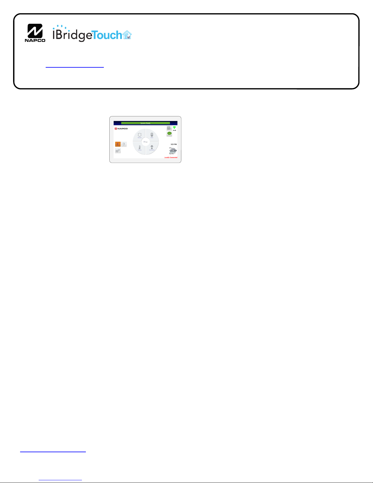
Napco's iBridge™ IBR-TOUCH and the wireless IBRTOUCH-WL are h igh-
resolution LCD touchscreen
tablets that provide seamless
access to all the features of
your Gemini security system.
Both touchscreens are simple
to use, with intuitive menudriven icons and prompts to
help guide you.
IBR-TOUCH / IBR-TOUCH-WL
Touchscreen Tablets
FEATURES
Each touchscreen model has many convenient features:
Touch screen control of security system
The model IBR-TOUCH connects to the Gemini se-
curity system 4-wire bus
The model IBR-TOUCH-WL is powered by a sup-
plied 12VDC adapter and wirelessly connects to your
security system
Integrated IP video viewing of cameras
High-speed, powerful quad core processor
Large high-resolution 1024 x 600 pixel display for clari-
ty
Intuitive capacitive touchscreen display with icons and
menu driven prompts
802.11 Wireless Wi-Fi Connectivity
Entry/Exit countdown displayed
Add or delete User Codes
Quickly and easily bypass zones
The touchscreen is one part of the integrated Napco
iBridge
keypad, Z-Wave
Compatible with the following control panels:
GEM-P816
GEM-P1632
GEM-P1664
GEM-P3200
GEM-P9600
GEM-X255
Important: A standard wired keypad must be installed
and enrolled in the system before adding a IBR-TOUCH
or IBR-TOUCH-WL touchscreen. In addition, be aware
that this standard wired keypad must be available for arming or disarming should the touchscreen(s) be temporarily
disabled during a firmware update. Visit
www.napcosecurity.com for ordering information and ap-
proved Z-Wave devices.
™
Remote Control Services that include a virtual
®
Home Controls and integrated video.
iBridge™ Touchscreen Tablets
Installation Instructions
WI2296LF 6/18
SPECIFICATIONS
Electrical Ratings
Speaker: 1 Integral 2W
.
.
Electrical Ratings
Screen on, idle: 300mA
Clicking menu items: 380mA. Important: Ensure
system standby current is sufficient; if not, a separate
UL-Listed Security and Signaling power-limited 12V
power supply for each touchscreen is required (see wiring diagrams).
Features
CPU: Quad core processor, (up to 1.6GHz)
Wi-Fi: 802.11b/g/n with i ntegral antenna
LCD Size: 7 inch digital screen
Resolution Ratio: 1024 x 600 x, 16:9 aspect ratio,
16.7 million colors
Pixels: 1024 x RGB (3) x 600
Touch Screen: Digital and full-screen, capacitive
Housing
Dimensions (HxWxD): 5-3/8 x 7-7/8 x 7/8 in. (13.7 x
20 x 2.2 cm)
Weight: 14.3oz (405g)
Operating Temperature: 0-49°C (32-120°F)
SELECTING THE MOUNTING LOCATION
The touchscreen requires power supplied from the control
panel keypad bus (wires are intended to be hidden within
the mounting surface). Important: Ensure system
standby current is sufficient; if not, a separate UL-Listed
Security and Signaling power-limited 12V power supply
for each touchscreen is required (see wiring diagrams).
Mount the touchscreen indoors only, and avoid high condensation areas such as bathrooms. Avoid mounting in
locations where direct sunlight or bright light shines directly on the screen.
INSTALLATION - HOLLOW WALL
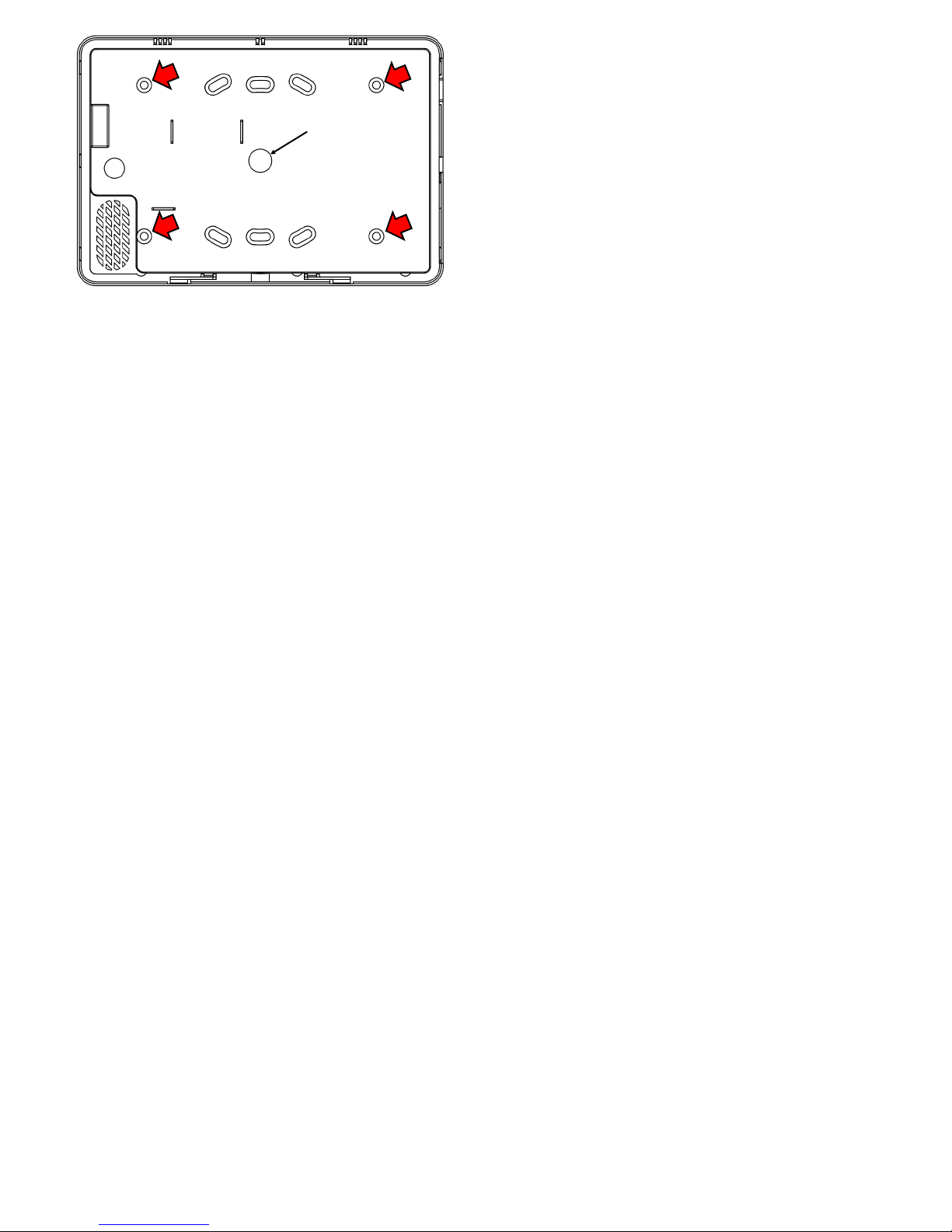
If installing into a 3-gang box, see instructions below. On
the Mounting Template (see page 12) and also shown in
the image below, note the location of the four rear case
mounting holes. In addition, four slotted holes are provided for mounting to a 2-gang box. Also note the location of
the center hole for use with routing the red/black/green/
yellow keypad bus wires (with the "wired" model IBR-
TOUCH) or the power wire (with the "wireless" model
IBR-TOUCH-WL). When the touchscreen is mounted,
the rear case center hole is intended to align with the center hole on the template.
1
Page 2
"center hole" for
power or
keypad bus wires
Touchscreen rear case mounting holes for hollow walls
(arrows) and the "center hole" for power / keypad bus wires
To secure the touchscreen directly to a hollow dry wall or
similar surface, proceed as follows:
1. Select a mounting location that is preferably at eye level
for easy viewing and that also allows the power / keypad
bus wires to be hidden within the mounting surface. At
the rear of the touchscreen, make note of the center hole
for the power / keypad bus wires (see image above).
2. With the final mounting location selected, place the
Mounting Template (see page 12) on the mounting surface and mark the four touchscreen mounting holes and
the center hole for power / keypad bus wires. Use a level to ensure horizontal mounting.
3. Using a 3/16" bit, drill the four touchscreen mounting
holes in the mounting surface. Insert wall anchors into
the holes and tap anchors into wall with a hammer. Use
part MX1327 #6 wall anchor, supplied.
4. Drill the center hole for the power / keypad bus wires in
the mounting surface. Snake the keypad bus wires from
the control panel (or the power wire from the DC power
supply) into the interior of the mounting surface, then out
through the center hole drilled in the mounting surface.
5. Detach the rear case from the touchscreen: Insert a flat
head screwdriver into the two slots at the bottom of the
touchscreen, then push and turn the screwdriver to unhook the two plastic tabs.
6. Insert the wires from the wall center hole through the
center hole of the rear case. Insert screws through the
four rear case mounting holes into the four wall anchors
using the supplied #6 sheet metal Phillips pan head 1"
screws (part SC655).
7. Connect the keypad bus wires to the terminal strip located inside the touchscreen (red to +12V, black to -GND,
yellow to YEL and green to GRN).
8. Push wires into the center hole in the mounting surface.
Place the top edge of the touchscreen over the two
hooks in the rear case and push the bottom of the
touchscreen until it snaps into place.
NOTE: If w iring to a 4-wire bus control panel, the IBR-
ZREMOTE or StarLink Connect radio must be wired
to the control panel bus and must have its own unique
keypad address. It is factory set as keypad address #1
but can be changed. If you wish to change the keypad
address with a touchscreen, the model IBR-TOUCH-WL
touchscreen MUST be used (or an IBR-TOUCH running
with the setting "Connect using Wi-Fi Only" enabled, and
thus is acting as a model IBR-TOUCH-WL). In addition,
the touchscreen must be connected to the same network
as the IBR-ZREMOTE or StarLink Connect radio. Any
attempt to change the keypad address using an IBRTOUCH without "Connect using Wi-Fi Only" enabled will
result in the changing of the keypad address of the integral RCM module located inside the IBR-TOUCH.
To change the keypad address, proceed as follows:
Power the touchscreen, place the control panel into Configuration Mode and enter 11123 FUNCTION (as you
normally would for Keypad Configuration Mode) and then
press FUNCTION until you see "Keypad Address".
Change address number and then press ON/OFF to
save. Place the alarm control panel back in normal
mode.
INSTALLATION - 3-GANG BOX
If installing the touchscreen rear case directly to a hollow
dry wall or similar surface, see instructions above. To secure to a 3-gang box, proceed as follows:
1. Select a mounting location that is preferably at eye level
for easy viewing. At the rear of the touchscreen, make
note of the center hole for the power / keypad bus wires
(see image on this page).
2. With the 3-gang box installed, snake the keypad bus
wires from the control panel (or the power wires from the
12VDC adapter) into the 3-gang box.
IMPORTANT: In the steps that follow, be careful not
to drill into the keypad bus / power wires inside the 3gang box.
3. Place the Mounting Template (see page 12) over the 3gang box and mark the location of the four mounting
holes in the 3-gang box.
4. Detach the rear case from the touchscreen: Insert a flat
head screwdriver into the two slots at the bottom of the
touchscreen, then push and turn the screwdriver to unhook the two plastic tabs.
5. Transfer the location of the four 3-gang box mounting
holes marked on the template in step 3 to the
touchscreen rear case.
6. Using a 3/16" bit, drill the four 3-gang box mounting
holes in the touchscreen rear case.
7. Insert the wires from the 3-gang box through the center
hole of the rear case. Insert screws through the four rear
case mounting holes (that were drilled in step 6) into the
four mounting holes in the 3-gang box. Use the supplied
#6 sheet metal Phillips pan head 1" screws (part SC655).
8. Connect the keypad bus wires to the terminal strip located inside the touchscreen (red to +12V, black to -GND,
yellow to YEL and green to GRN).
9. Push wires from the center hole of the touchscreen into
the 3-gang box. Place the top edge of the touchscreen
over the two hooks in the rear case and push the bottom
of the touchscreen until it snaps into place.
2
Page 3

1: WIRING OVERVIEW with the IBR-TOUCH only ("Keypad Only" Mode)
STANDARD
KEYPAD
RED
BLACK
GREEN
YELLOW
KEYPAD BUS
(–)
(+)
Power Supply
Power Supply: If the sys-
tem standby current is insufficient for the 380mA required for the IBR-TOUCH,
use a separate UL-Listed
Security and Signaling power-limited 12V power supply.
Be sure the negative terminals of the power supply and
control panel are connected.
CONTROL
PANEL
BLACK
RED
IBR-TOUCH*
*With the IBR-TOUCH-WL,
use a StarLink Connect
radio or an IBR-ZREMOTE.
Internet
BROADBAND
CAT5 to Router
CUSTOMER ROUTER
(Wireless)
MODEM
Note: "Keypad Only" mode is
selected in the Setup Wizard, when
the IBR-TOUCH is first started (see
the IBR-TOUCH & IBR-TOUCH-WL
Quick Start Guide (WI2297) for
more information.
For remote services with Z-Wave,
use an IBR-ZREMOTE or a
StarLink Connect radio. The
hardwired IBR-TOUCH includes Wi
-Fi capability for wireless connection
through the customer's "Wi-Fi"
network.
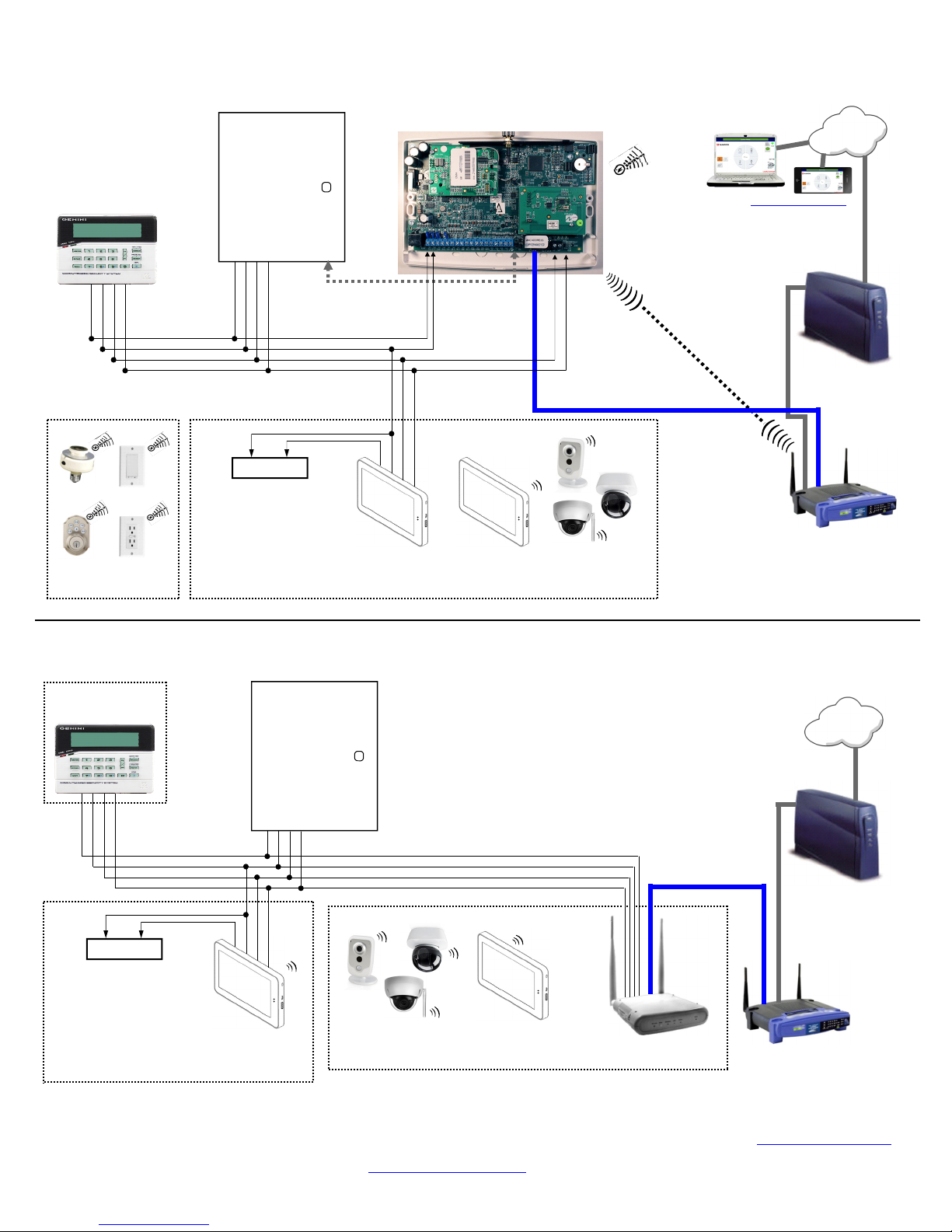
2: WIRING OVERVIEW with the IBR-ZREMOTE
STANDARD
KEYPAD
RED
BLACK
GREEN
YELLOW
KEYPAD BUS
(–)
(+)
Power Supply
Power Supply: If the system
standby current is insufficient for
the 380mA required for the IBRTOUCH, use a separate ULListed Security and Signaling
power-limited 12V power supply.
Be sure the negative terminals of
the power supply and control
panel are connected.
CONTROL
PANEL
BLACK
RED
IBR-TOUCH
TO PANEL SERIAL PORT (only
needed for IBR-ZREMOTE CS
communication or panel
downloading)
IBR-TOUCH-WL
IBR-ZREMOTE
RED
BLACK
(((
CAMERAS
Connection
(1) CAT5 Ethernet
Connection
GREEN
YELLOW
CUSTOMER ROUTER
(Wireless)
Z-WAVE DEVICES
Internet
(2) CAT5 Ethernet
Access at Access at
www.NapcoNOC2.com
(3) CAT5 to Router
BROADBAND
The hardwired IBR-TOUCH
includes Wi-Fi capability for
wireless connection through the
customer's "Wi-Fi" network.
MODEM
3
Page 4
3: WIRING OVERVIEW with a StarLink Connect Radio
STANDARD
KEYPAD
RED
BLACK
GREEN
YELLOW
KEYPAD BUS
Z-WAVE DEVICES
CONTROL
PANEL
TO PANEL SERIAL
PORT ( only needed
for panel downloading;
use part SLE-DLCBL )
(–)
(+)
Power Supply
Power Supply: If the system
standby current is insufficient for
the 380mA required for the IBRTOUCH, use a separate ULListed Security and Signaling
power-limited 12V power supply.
Be sure the negative terminals of
the power supply and control
panel are connected.
StarLink Connect Radio
BLACK
RED
BLACK
RED
IBR-TOUCH
IBR-TOUCH-WL
Note: The IBR-WIFI-MOD
Wireless Panel Interface is optional.
GREEN
YELLOW
(Requires a CAT5 connection to the
customer's router or the SLE-WIFI-MOD to
wirelessly connect to the customer's router)
(((
CAMERAS
Internet
Access at www.NapcoNOC2.com
BROADBAND
MODEM
CUSTOMER ROUTER
(Wireless)
4: WIRING OVERVIEW with the ISEE-WAP
STANDARD
KEYPAD
RED
BLACK
GREEN
YELLOW
KEYPAD BUS
BLACK
RED
(–)
(+)
Power Supply
Power Supply: If the system
standby current is insufficient for
the 380mA required for the IBRTOUCH, use a separate ULListed Security and Signaling
power-limited 12V power supply.
Be sure the negative terminals of
the power supply and control
panel are connected.
IBR-TOUCH
ISEE-WAP: Wireless Pan el Int erface, commu nic ates between Internet, Gemin i Con trol Panel (th rou gh t he 4-wire keypad bus), the IBR-TOUCH
Touchscreen Tablet and optional iSeeVideo wireless cameras. Only use the ISEE-WAP if remote services or if Z-Wave are NOT required. Therefore, the
customer may ONLY control their alarm system or view video LOCALLY through an optional IBR-TOUCH tablet or video through mobile devices running the
iBridge mobile app, using the iBridge Wi-Fi service provided by the ISEE-WAP. NOTE: A remote service subscriber account on www.ibridgeonline.com is
NOT required for LOCAL ONLY control. For remote services and Z-Wave, use the IBR-ZREMOTE. For remote services without Z-Wave, use the iRemote-
MOD Remote Control Module and ac cess your keypad at www.myremot ekeypad.com.
CONTROL
PANEL
CAMERAS
IBR-TOUCH-WL
(((
ISEE-WAP
CAT5 to Router
(((
Internet
BROADBAND
MODEM
CUSTOMER ROUTER
(Wireless or Wired-only)
4
Page 5

DEALER & USER SETTINGS MENUS
IBR-TOUCH App
"System Settings" Button
This "System Settings" button can display either a list of "useronly" selections (adapted for home/business owners), or a list of
"dealer-only" selections (customized for installers), depending on
the how this button is tapped and pressed:
Dealer Settings: To display the list of "dealer-only" selec-
tions, press and hold this button (password required)
User Settings: To display the list of "user-only" selec-
tions, simply tap this button once
When accessing the Dealer Settings, (again, by pressing and
holding this button), a popup appears requesting a password.
This password request signifies that the Dealer Settings menu will
be displayed. Type the dealer password (default is "admin") and
tap OK. Tap Yes to the warning popup that appears, and the
Dealer Settings menu opens.
For Z-Wave menu selections, see the Using your iBridge® IBR-
TOUCH Series Z-Wave
DEALER SETTINGS
Setup Wizard
Tap to re-start the Setup Wizard to configure how the IBR-
TOUCH / IBR-TOUCH-WL will be used, its Wi-Fi connection
settings to the customer's Wi-Fi network and iBridge radio,
and optionally the NAPCO StarLink account(s). See the
NAPCO iBridge IBR-TOUCH & IBR-TOUCH-WL Quick
Start Guide (WI2297) fo r s tep-by-step instructions to help
guide you through the Wizard.
Run Diagnostics
Tap to run a system diagnostics test for components selected
the last time the Setup Wizard was run (typically when the
touchscreen was first powered). Functional components are
marked with a check; items not configured or not enabled are
marked with an "x". Selections are blank when the Wizard is
run for the first time. If you wish to continue through the Set-
up Wizard (described below), tap Configure; otherwise
tap Continue to App to return to the Home Screen (or Test
Again to repeat the tes t). See the NAPCO iBridge IBRTOUCH & IBR-TOUCH-WL Quick Start Guide (WI2297)
for step-by-step instructions to help guide you through the
Wizard.
Security
EZ-ARM: Check to enable Easy Arming (ability to arm
the alarm system quickly by simply tapping ENTER or
ON/OFF, Night, Away or Stay). Each touchscreen
may be individually programmed for Easy Arming.
Disarming still requires entry of a valid user code.
®
Home Automation System (OI394).
Note: Do not program Easy Arming in UL installa-
tions. The alarm control panel must be programmed
to support this feature.
EASY EXIT: Check to enable Easy Exit. While armed i n
the Interior Bypass/Stay Mode, Easy Exit can be initiated by pressing and holding the Disarm "pie wedge"
button. Easy Exit restarts the Exit delay (the top banner on the touchscreen changes to read "ARM ING
STAY...") allowing a User to exit an armed premises
without disarming and rearming the system. Note:
Do not program Easy Exit in UL installations. The
alarm control panel must be programmed to support
this feature.
Number of Zone Areas: Some systems may be divid-
ed, or partitioned, into smaller independent subsystems, which are referred to as Areas. Tap to select the
number of Areas in the alarm system. Note: Each Area
may be controlled by its own touchscreen or by a
touchscreen of a different Area through Managers
Mode (a low-security operating mode that allows arming by Area).
Connection Settings: Displays the network communica-
tion and automatic identification settings used between
the IBR-TOUCH / IBR-TOUCH-WL and the customer's
router (and/or IBR-ZREMOTE / StarLink radio).
Serial Interface: Indicates "Enabled" if IBR-TOUCH
("hardwire" model) is used.
IP Address: Displays the private TCP/IP protocol ad-
dress used for communications between the IBRTOUCH / IBR-TOUCH-WL and the customer's router
(and/or IBR-ZREMOTE / StarLink radio).
Port No.: Displays the port number used for network
activities as set by the IBR-ZREMOTE or StarLink radio.
Autodiscovery Options: "Enabled" allows for the o n-
going automatic recognition of and connection between
the IBR-TOUCH / IBR-TOUCH-WL and the IBRZREMOTE or StarLink radio. Includes discovery and
ports established during the initial handshake process.
Time interval to request status: Displays the duration
between autodiscovery process activations.
Connect using Wi-Fi Only
When checked, a model IBR-TOUCH "hardwired"
touchscreen is converted to a model IBR-TOUCH-WL
"wireless" touchscreen; i.e. signals received into the 4-wire
bus terminals (inside the IBR-TOUCH) are ignored, with the
exception of the two power terminals (thus the touchscreen
can be powered by the control panel 4-wire bus or by wiring
power directly to the power terminals).
Tablet
Connection:
(1) Change/Create CUSTOM IBRIDGE ISEE-WAP Wi-
Fi Name and KEY: Select this feature to modify
the factory default network settings of the ISEEWAP and touchscreen. The Preferred Network dia-
log appears, allowing a new Wi-Fi Name (SSID)
and a new secret Key to be entered. Note that this
information can be changed at any time by rerunning this feature. Note: The ISEE-WAP and all
wireless cameras in the system must be unlocked
before using this feature.
5
Page 6

(continued from previous page)
Dealer Settings Menu
(2) Configure Wireless Camera: When wireless cam-
eras are first powered, they (by default) automatically attempt to connect with the first ISEE-WAP that
answers using the default SSID of "PUBLIC". This
feature requests all cameras within range to attempt
to connect with an ISEE-WAP using the custom
SSID and secret Key previously c reat ed i n the
menu item named "(1) Change/Create CUSTOM
IBRIDGE ISEE-WAP SSID and KEY" described
above. Note: All wireless cameras in the system
must be unlocked before using this feature (will read
"Camera is unlocked" in popup).
(3.a) Lock Down IBRIDGE ISEE-WAP: Tap to protect
the ISEE-WAP / touchscreen connection by a "lock
down" process, ensuring a fixed connection between the ISEE-WAP / touchscreen device pairs.
This selection disables the automatic connection
process that attempts to connect the touchscreen
with the first ISEE-WAP that answers using the default SSID of "PUBLIC".
(3.b) Unlock IBRIDGE ISEE-WAP: To reverse the
"Lock Down" process described in the previous
menu selection.
(4) Restart Wi-Fi: Tap to perform a "warm boot" re-
start operation of the Wi-Fi, where the power is not
turned off and back on, and with the app running.
Minutes to check connection integrity: Tap to set
the number of minutes the touchscreen will automatically attempt a restoration of the wireless connection between the touchscreen and the ISEE-WAP
should this connection be interrupted. Selectable
durations are: 1, 3, 5, 7, 10, 15 and 20 (minutes).
BSSID used to LOCKDOWN IBRIDGE: Tap to enter
a new "broadcast" SSID (named "BSSID" in this
menu) to be stored in the touchscreen's memory, to
be used by default when the touchscreen is rebooted, powered off/on or emerges from Screen lock.
Factory Default:
Tap to remove all user data and restore the IBR-
TOUCH / IBR-TOUCH-WL back to its original out-of-box
factory condition.
iBridge Updater
Update Server Address: Displays the IP Address
and Port number used by the network server when
the menu selection Check For Updates (described
below) is tapped.
Check for Updates: Tap to automatically check to
see if a newer version of the touchscreen firmware
is available from the location specified in the
"Source" menu item (descr ibed abo ve). If a newer version is available, follow the on-screen prompts
to load the firmware update files, as necessary.
Current Version: Displays the current version num-
ber of the IBR-TOUCH / IBR-TOUCH-WL firmware.
Update iBridge Application from USB: Select if the
new firmware update is located on USB memory
(such as a thumb drive, portable hard drive, memory
stick, etc.), and you wish to use the USB socket located on the side of the IBR-TOUCH / IBR-TOUCHWL to re-install the firmware. Note: The update file
must be placed in a folder named "napco" (case
sensitive) located in the top root directory.
Update Logo: Insert a USB thumb drive to add your
logo image to the Home Screen and "Keypad Skin".
The logo must be named "logo.png" (case sensitive)
and must be located in a folder named
"dealerLogo" (case sensitive) located at the top root
directory of the thumb drive. When this logo is added successfully and later the logo is tapped, the
touchscreen opens its default browser to the
webpage specified in the Update Infopa ge menu
selection, detailed below. Note: Although the
touchscreen searches for the specific file name
"logo.png", the image file itself may be a .png, .bmp
or .jpeg format. However, the file must be re-named
"logo.png".
Update Infopage: Insert a USB thumb drive to add
an image that will display website or other corporate
information. The file must be named
"dealer.png" (case sensitive) and must be located in
a folder named "dealerLogo" (case sensitive) located at the top root directory of the thumb drive.
When a logo is added to the Home Screen and
"Keypad Skin" using the Update Logo menu selec-
tion (see above) and this logo is later tapped, the
"dealer.png" image file will appear enlarged on the
touchscreen.
Update Android OS via USB: Select to update the
Android operating system. Be sure the update .zip
file (WinZip) is located in the top root directory of the
USB drive (such as a thumb drive, portable hard
drive, memory stick, etc.). Use the USB socket located on the side of the IBR-TOUCH / IBR-TOUCHWL to install the OS. Once inserted into the USB
socket, tap this selection (if already inserted, remove
and re-insert). Allow up to 15 seconds for the update process to begin; once started, DO NOT remove the USB drive!.
Password Configuration: Allow s you to change the
password used to access the Dealer Settings menu. In
the Change Settings password popup that appears,
press the empty field with the flashing cursor to open an
onscreen keyboard, allowing you to type the new password. Check the optional "Show password" checkbox to
view the populated characters. Press "Change Pass-
word" to enter or "Cancel" to exit without changing.
Video
Allows changes to the video data settings received by
the IBR-TOUCH / IBR-TOUCH-WL. Note: This Video
menu selection appears (and all of the selections below)
only if "ISEE Series Cameras" is selected in the Setup
Wizard (see WI2297 for more information about the Setup Wizard).
Camera List
Camera Auto Discovery: Check to allow the
touchscreen to automatically attempt to capture and
6
Page 7

(continued from previous page)
Dealer Settings Menu
display video stream data found within the network to
which the touchscreen is connected. This feature is
designed to operate within the iSeeVideo system.
See http://www.napcosecurity.com/video.html for more
information.
Configure Wireless Camera: Allows the
touchscreen to remotely change the wireless settings
of the selected camera. When this feature is selected,
be aware that the network path from the touchscreen
to the IBR-ZREMOTE / StarLink Connect radio and to
the camera may take several seconds to be established. Note: When selected, a popup appears, that
reads:
"Please make sure to first connect an Ethernet
cable to the router and to then connect power to
the camera. Do you wish to proceed with Wireless
Camera Configuration?"
1. The camera must be powered and wirelessly connected to the network before proceeding.
2. Tap Yes to proceed or No to exit without saving
any changes. If you tap Yes, the touchscreen will
scan the network and all available cameras will be
listed (by IP address) in the Camera List that appears. Tap to select a camera in the list, and a
Configure Wireless Camera popup appears,
allowing you to either Lock or Unlock the selected
camera. Locking the camera will ensure a permanent connection between the camera and the
touchscreen.
3. Select either the Lock or Unlock radio button, and
tap Configure to proceed or tap Cancel to exit with-
out saving changes.
Camera Manual Discovery: Allows you to browse
for and select to use a specific camera attached to the
iBridge network using the touchscreen. The following
two steps ("Select…" and "Discover…" shown below
are required:
1. Select camera to discover: (Step 1): Tap to
select the camera you wish to discover and capture
its video stream data.
2. Discover IP Camera: (Step 2): Tap to initiate
the network scanning process to discover the selected camera. Upon discovery, the video will be
available for display from the touchscreen Home
Screen (Vide o button).
Launcher
(Reserved for NAPCO use only)
Home
Weather Options - Local weather reports can be displayed
on the Home Screen.
Refresh Frequency: Tap to set how often to auto-
matically update the weather report feed. Selections
include 5, 10, 15, 20, 30, 40, 50, 70, 80, 90 and 100
minutes. More frequent updates increase data use and
slightly decrease battery life between charges.
Weather Feed: Check to display a weather report
feed on the Home Screen. Uncheck to remove the
weather feed from the Home Screen. Note: To cus-
tomize the weather report feed to a particular Zip
Code, see the following menu entries below.
Zip code entry: Check to associate the weather
report feed to the area of the United States specified
by the Zip Code entered in the field below. Uncheck
to disassociate the weather feed from this Zip Code.
Zip Code: Tap to set the Zip Code to which the
Weather Feed is associated.
Update Z-Remote Clock - Synchronizes the IBR-
ZREMOTE module or StarLink radio internal clock
with the same time as the IBR-TOUCH / IBR-TOUCHWL.
Lock Display on Keypad View - Enabled (checked)
when "Keypad Only" is selected in the Setup Wizard
(see below). When enabled, pressing Security in the
Home Screen immediately displays the virtual security
system Gemini keypad, and not the intermediary "pie
wedges" that are displayed when "Full Functionality"
is selected in the Setup Wizard.
Set Keypad as the Only View - When enabled, pressing
the Home button immediately and continually displays
the virtual security system Gemini keypad. Note: The
User Setting "Enable KeySwitch Arming" (detailed
above) must first be disabled.
Modify Z-Wave Settings
For dealers who wish to disallow customer changes to the
home automation Z-Wave system, unchecking (disabling)
this setting disables the User Settings menu feature named
"Automation Management (z-wave)" . Conversely, check
this setting to enable the User Settings menu feature named
"Automation Management (z-wave)", allowing control of
the Z-Wave home automation components within the system
using the "User Settings" menu (where an touchscreen Deal-
er Settings password is not required).
Automation Management (z-wave)
Opens the Automation Management screen, allowing the
configuration of Z-Wave devices, including the assignment of
devices to Groups, the creation of Z-Wave Events, etc. See
the Using your iBridge
®
IBR-TOUCH Series Z-Wave®
Home Automation System (OI394) for more infor-
mation.
Emergency Button
Check to enable the "E" (Emergency) button on the IBR-
TOUCH / IBR-TOUCH-WL Home Screen. If unchecked,
although the "E" (Emergency) button will appear on the
Home Screen, it will be disabled and the message,
"Permission Denied. Please Contact Dealer." will appear
when tapped.
Change Login URL
Not Used; do not change this selection.
7
Page 8

User Settings Menu
USER SETTINGS
Setup Wizard (see DEALER SETTINGS) Note: In User
Settings, a limited wizard is available (with Wi-Fi and
iBridge credentials only). Use this feature in Dealer Settings for full functionality.
Run Diagnostics (see DEALER SETTINGS)
Test Wi-Fi connection
Tap to analyze the strength of the wireless connection
between the IBR-TOUCH / IBR-TOUCH-WL and the customer's router (and/or ISEE-WAP). When installing the
IBR-TOUCH / IBR-TOUCH-WL, be sure the large "Wi-Fi
Icon" is colored green (OK) to ensure a strong wireless
signal. In addition, the signal strength in dBm units (signal
level relative to 1 milliwatt) is provided for those more familiar with readings expressed using standard radio communication terminology. The dBm units are expressed in
negative numbers; therefore the higher the negative number, the weaker the signal. For example, a reading of -20
is stronger than -30.
Clean Tablet Screen
Allows you to safely clean the touchscreen display surface
without making changes to the system. Tap to set a
length of time during which all inputs to the system
through the touchscreen are disabled. Enter a time in
seconds, tap Yes, and the screen will turn black with dark
gray numbers counting up to the number of seconds entered, then will count down to zero and return to normal
operation. For example, entering "20" will disable the keypad for a total of 40 seconds.
Change LED Level
Provides a sliding bar to control the brightness of the red
and green LEDs located on the face of the tablet.
Tablet Settings
Sound: Controls sound intensity and feedback set-
tings (unavailable with some models).
Volumes: Set the sound for video, Notifications
and Alarms.
Touch sounds: Check to enable feedback sound
made when certain onscreen items are touched.
Display: Allow s changes to the IB R-TOUCH / IBR-
TOUCH-WL display screen
Brightness: Tap to open a sliding status bar con-
trol. Increase or decrease the screen brightness
by sliding your finger left or right across the status
bar
Sleep: Specifies how much user idle time
(touchscreen is operational but not being used)
must elapse before the screen dims. The default
setting is "never". Note: When this feature is ena-
bled and the screen dims, the IBR-TOUCH also enters "sleep mode", an inactive state to save power.
To re-awaken, simply touch the screen or a nonscreen button. Screen timeout selections include 15
seconds, 30 seconds, 1 minute, 2 minutes, 10
minutes, 30 minutes and never.
Font size: Controls the size of the lettering that ap-
pears in the Dealer and User Settings menus.
Date & Time:
Automatic: When checked to enable, retrieves date/
time data automatically from network resources.
When enabled, the next two selections are ghosted
("grayed out" and not selectable).
Set date: Tap to open a dialog that allows the
month, day and year to be manually set in the IBRTOUCH. Note: The "Automatic" menu selection
(above) must be unchecked to enable this menu
item.
Set time: Tap to open a dialog that allows the cur-
rent time to be manually set in the IBR-TOUCH.
Note: The "Automatic" menu selection (above)
must be unchecked to enable this menu item.
Select time zone: Tap to select a time zone to be
used in the touchpad.
Use 24-hour format: Check to display 24-hour mili-
tary time, as measured in hours numbered to twenty
-four from one midnight to the next. For example,
3:23 pm would be displayed as "15:23".
About Tablet:
Update OS via USB: Select to update the Android
operating system. Be sure the update .zip file
(WinZip) is located in the top root directory of the
USB drive (such as a thumb drive, portable hard
drive, memory stick, etc.). Use the USB socket located on the side of the IBR-TOUCH / IBR-TOUCHWL to install the OS. Once inserted into the USB
socket, tap this selection (if already inserted, remove
and re-insert). Allow up to 15 seconds for the update process to begin; once started, DO NOT remove the USB drive!
Kernel version: For NAPCO use only. Details the
version of the kernel within the operating system of
the IBR-TOUCH / IBR-TOUCH-WL.
Build Number: The file name of the firmware cur-
rently running.
Reboot Tablet
Tap (and tap OK to the warning popup) to re-start the IBR-
TOUCH / IBR-TOUCH-WL.
Home (see DEALER SETTINGS)
Automation Management (see DEALER SETTINGS)
Enable KeySwitch Arming
When checked (enabled), allows a zone input to be used to
arm/disarm the security system. The Area will arm/disarm
when the programmed zone is momentarily shorted through
8
Page 9

(continued from previous page)
User Settings Menu
use of a momentary switch. See the setting Home > Set
Keypad as the Only View, below .
Voice
Check to enable (or uncheck to disable) IBR-TOUCH /
IBR-TOUCH-WL touchscreen voice prompts.
App Version
Displays the current version number of the IBR-TOUCH /
IBR-TOUCH-WL firmware.
FCC Statement
This equipment has been tested and found to comply with the limits for a Class B digital device, pursuant to Part 15 of the FCC Rules. These limits are designed to provide reasonable protection against
harmful interference in a residential installation. This equipment generates uses and can radiate radio
frequency energy and, if not installed and used in accordance with the instructions, may cause harmful
interference to radio communications. However, there is no guarantee that interference will not occur in
a particular installation. If this equipment does cause harmful interference to radio or television reception, which can be determined by turning the equipment off and on, the user is encouraged to try to correct the interference by one or more of the following measures:
-- Reorient or relocate the receiving antenna;
-- Increase the separation between the equipment and receiver;
-- Connect the equipment into an outlet on a circuit different from that to which the receiver is connected;
-- Consult the dealer or an experienced radio/TV technician for help.
Changes or modifications not expressly approved by the party responsible for compliance could void the
user's authority to operate the equipment.
The distance between user and products should be no less than 20cm.
Important: iBridge is a trademark of Napco Security Technologies, Inc. All other trademarks, service marks, and product or service
names described in this manual are for identification purposes only and may be trademarks or registered trademarks of their respective owners. The absence of a name or logo in this document does not constitute a waiver of any and all intellectual property rights that NAPCO Se-
curity Technologies, Inc. has established in any of its product, feature, or service names or logos. For NAPCO LIMITED WARRANTY information, see WI1980.
9
Page 10

PROGRAMMING WHEN USED WITH THE IBR-ZREMOTE
CONTROL PANEL FIRMWARE
IMPORTANT: Before upgrading firmware, the control
panel program must be uploaded to be re-downloaded when
the upgrade is complete.
The alarm control panel must have the correct firmware version installed to use all features of the IBR-ZREMOTE and
the new iBridge Messenger service:
PCD-Windows Quickloader: V6.12 or greater
(located on the enclosed IBR-ZREMOTE support CD)
Control panels GEM-X255, P9600 and P3200 require
firmware version V60A23 or greater (included in IBR-
ZREMOTE box)
Control panels GEM-1664, P1632 and P816 require
firmware version V31A or greater (included in IBR-
ZREMOTE box)
New "NO EPROM" GEM-P3200, P9600 or X255 control
panels require firmware version V71K or greater (CD in-
cluded in the IBR-ZREMOTE BOX)
Note: The following version control panels may be
upgraded for iBridge compatibility:
GEM-P3200 and P9600 controls running firmware ver-
sion 20 or greater, released in May of 1999
All GEM-X255 control panels
Any new GEM-P3200, GEM-P9600 or GEM-X255 control
panel running V70 or greater firmware does not require
an EPROM upgrade, it is iBridge compatible out of the
box.
GEM-P816 and GEM-P1632 control panels running firm-
ware version 10D or greater, released in November of
2005. The PC board revision number can be identified
by the revision number inside the triangular shaped sticker affixed to the PCB (requires 32 pin EPROM socket in
the control panel)
All GEM-P1664 control panels
UPGRADING THE EPROM CHIP
A. If installing the IBR-ZREMOTE on a previously pro-
grammed control panel, launch Quickloader V6.12 (or
greater) and upload the control panel program configuration to an account on your PC. In all cases ensure a conventional keypad is connected at keypad address 1 for
steps that follow.
B. Remove power from the control panel, disconnect the
battery wires and replace the EPROM with the new version.
C. Power the control panel, reconnect the battery wires, en-
ter Direct Address Program Mode and Cold Start the
panel:
To cold start the GEM-P186, GEM-P1632 or GEMP1664 Control Panels:
1. Enter Dealer Program Mode from keypad #1 (the default Dealer Code is 4 5 6 7 8 9).
2. Once in Dealer Program Mode, press Reset.
3. In Direct Address Programming Mode, enter the following address:
Panel firmware V11 and lower, enter address 1198;
firmware V30 and higher, enter address 2286
4. Press the ON / OFF button to save.
5. Press Reset twice to exit Dealer Program Mode. Veri-
fy the keypad display reads: E09-00 Cold Start.
To cold start the GEM-P3200, GEM-P9600 or GEMX255 Control Panels:
1. Enter Dealer Program Mode from keypad #1 (the Master Security Code is printed on the silver shield inside
the control panel housing). Once in Dealer Program
Mode, press Reset.
2. In Direct Address Programming Mode, enter address
4093.
3. Press the ON / OFF button to save.
4. Press Reset twice to exit Dealer Program Mode. Veri-
fy the keypad display reads: E09-00 Cold Start.
D. Download the saved control panel program configuration
back into the control panel or create and download new
control panel programming.
PROGRAMMING THE IBR-ZREMOTE IN
QUICKLOADER V6.12 (or greater)
In Quickloader V6.12 (or greater), in Keypad Assignment,
select the keypad address you will set up in step 5 for the
IBR-ZREMOTE, and change the keypad address Type to
"RCM" and add the k eypad into the Area (see image
at right), select EZ Arm (6 columns to the right on the
same screen). In the Keypad Features tab, check
"Disable Code-Required-for-FM-Level 1" (GEMP3200 / P9600 / X255 panels only).
PROGRAMMING THE TOUCHSCREEN
"KEYPAD ADDRESS" AND "KEYPAD TYPE"
Each IBR-TOUCH touchscreen must have its own unique
Keypad Address; in addition, the Keypad Type must be defined. Before proceeding, the Setup Wizard must be performed. The Setup Wizard begins automatically when the
touchscreen is first started, but can also be manually started
in both the Dealer Settings Menu (see page 5) and the User
Settings Menu (see page 8).
For Se tup Wizard step-by-step instructions for connect-
ing the touchscreen to an existing Wi-Fi Network
(networks without an ISEE-WAP), see the NAPCO
iBridge™ IBR-TOUCH & IBR-TOUCH-WL Quick Start
Guide (WI2297) available at http://
tech.napcosecurity.com/.
To connect the touchscreen to an existing Wi-Fi Network
(networks with an ISEE-WAP), see the iBridge® Suite
Quick Start (WI1980) available at http://
tech.napcosecurity.com/.
The Keypad Type is factory set as a GEM-RP1CAe2
"Classic" style keypad and is set to Keypad Address #1.
These factory settings can be changed if required. To
change the Keypad Type and Keypad Address, the
touchscreen must be powered on; the IBR-TOUCH must be
wired to the control panel keypad bus, and the IBR-TOUCHWL must have a local wireless connection to the "local"
StarLink Connect radio or the IBR-ZREMOTE Controller that
is physically located "locally", i.e. inside the premises and
connected to the control panel.
10
Page 11

1. Put the control panel into Keypad Configuration Mode by
moving the configuration jumper to the bottom two pins
("CONFIG"), located inside the control panel.
2. Using the IBR-TOUCH hardwired tablet, at the Home
Screen tap "SECURITY" then "OTHER OPTIONS" and
select "KEYPAD MODE". After putting the control panel
into Keypad Configuration Mode, it normally takes up to
40 seconds for the keypad on the IBR-TOUCH to read
"out of system". The keypad will display "01 Out of Sys-
tem RCM MODULE".
3. Press 1 1 1 2 3 FUNCTION to enter Keypad Configura-
tion Mode.
4. Tap FUNCTION repeatedly until the configuration keypad
displays "Keypad Address".
5. Enter the correct address and tap ON/OFF to save.
(Note: Keypad address will not change until you tap
ON/OFF).
6. Tap FUNCTION repeatedly until the keypad displays
"Keypad TYPE RP1CAE2".
7. Tap INTERIOR or INSTANT to toggle between the key-
pad model names. Either select "RP1CAE2" for the
"Classic" keypad type or "K1CA" for the "K Style" (Stay/
Away) keypad type. When selected, tap ON/OFF or EN-
TER to save, and then tap RESET to exit.
8. Return the control panel CONFIG jumper back to the top
two pins ("NORM"). "System Ready" should appear
on the keypad if all zones are closed.
UPDATING THE TOUCHSCREEN
FIRMWARE WITH USB DRIVE
To update the touchscreen firmware with
a USB drive, the "update.zip" file must be
located in the top root directory (the top root folder) of the
USB drive. The name of the update file must be
"update.zip" (cAsE sEnSiTiVe).
1. At the Home Screen, insert the USB drive into the USB
socket located on the side of the unit and wait for the
light on the USB drive to turn on.
2. Tap the System Settings button ("gear" icon,
shown at right).
3. Tap Tablet Settings > About tablet > Up-
date OS Via USB. The update process
will start within about 15 seconds. When the
following popup appears, tap Install.
4. After several minutes, a popup will appear indicating the
update process is complete (tap OK).
Note: An alternat ive to the above process is to simp-
ly power down the unit, insert the USB drive, power up
the unit and wait for the popup shown in step 3 (above)
to appear.
System Settings
button
PROFILE SIDE BUTTONS
AND FEATURES
(Reserved for future use)
Power Button
Press and hold: Popup ap-
pears allowing choice of Power
off, Reboot or Menu+, allow-
ing you to update the operating
system and/or the app.
(Reserved for future use)
Micro-B USB 2.0 Socket
For use with Technical Sup-
port, allows access to system
log files.
USB-A 2.0 Socket
Insert USB flash drive for up-
dating touchscreen firmware.
(Reserved for future use)
11
Page 12

IMPORTANT
WHEN PRINTING OR PHOTO-
COPYING
ALWAYS SELECT PRINTING
OPTIONS TO ENSURE THAT
COPIES ARE PRODUCED
WITHOUT SIZE ADJUSTMENTS.
ERIFY THE DIMENSIONS OF
V
THIS BOX ARE 2.000 X 2.000
INCHES ± 0.010.
A TEMPLATE,
MOUNTING TEMPLATE
12
X
INCH
INCH
BOX IS
1
1
ENSURE THIS
 Loading...