

Page 1
R
333 Bayview Avenue
Amityville, New York 11701
For Sales and Repairs, (800) 645-9445
For Technical Service, (800) 645-9440
Publicly traded on NASDAQ Symbol: NSSC
© NAPCO 2005
FREEDOM Wireless
F-TP Touchpad, F-LTRANS and F-TAB
INSTALLATION INSTRUCTIONS
WI1439 10/05
GENERAL DESCRIPTION
The NAPCO Freedom Deadbolt-Activated Home Protection
System, a revolutionary new concept in residential security, com-
bines intuitive interactive arming with a passive disarming scheme,
providing a system which is not only effortless to use, but also
100% false alarm resistant during the critical arming and disarming
sequences.
The system is armed with a simple push of a button (L
or M) on the F-TP Touchpad control module, followed by the
locking of the home’s deadbolt. To disarm, simply unlock the
deadbolt.
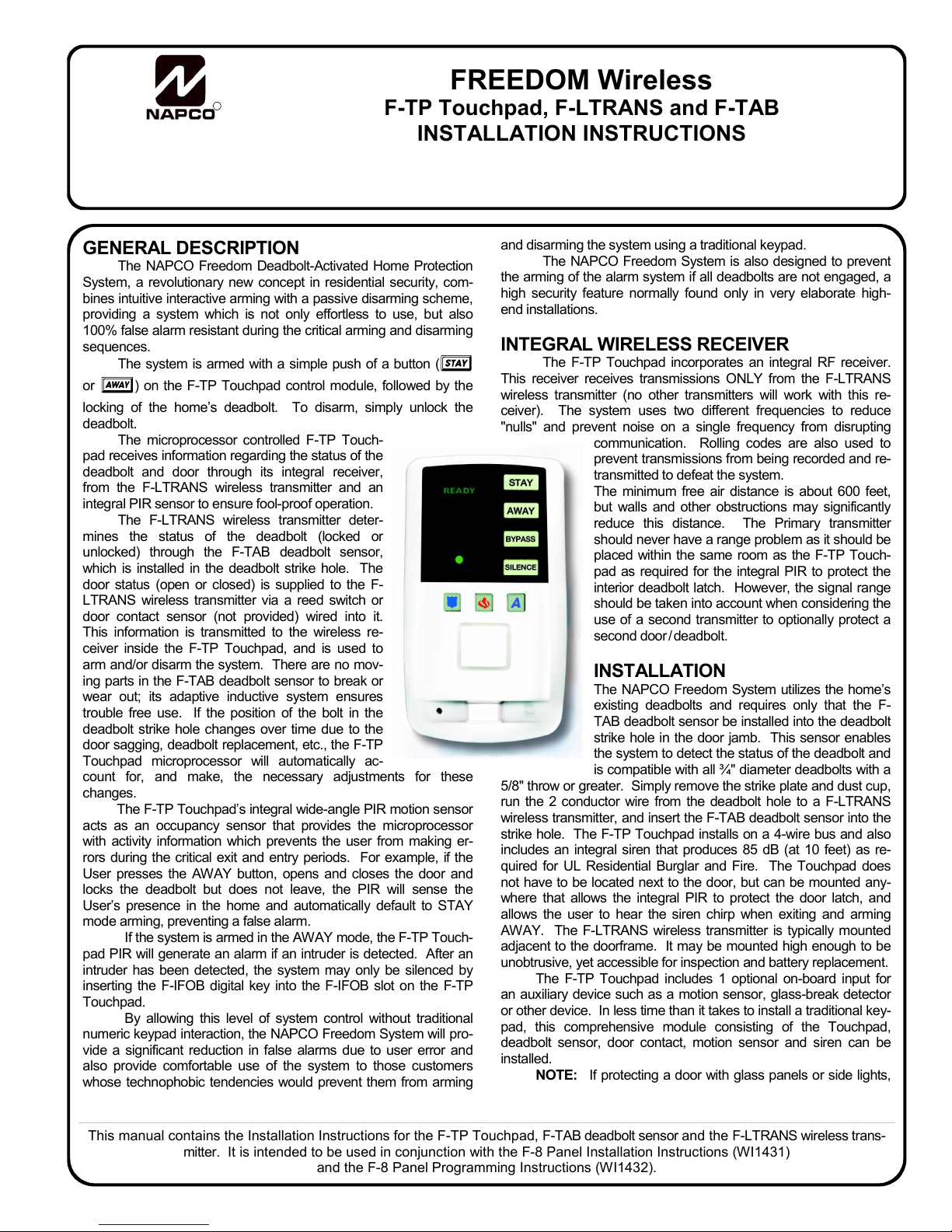
The microprocessor controlled F-TP Touch-
pad receives information regarding the status of the
deadbolt and door through its integral receiver,
from the F-LTRANS wireless transmitter and an
integral PIR sensor to ensure fool-proof operation.
The F-LTRANS wireless transmitter deter-
mines the status of the deadbolt (locked or
unlocked) through the F-TAB deadbolt sensor,
which is installed in the deadbolt strike hole. The
door status (open or closed) is supplied to the F-
LTRANS wireless transmitter via a reed switch or
door contact sensor (not provided) wired into it.
This information is transmitted to the wireless re-
ceiver inside the F-TP Touchpad, and is used to
arm and/or disarm the system. There are no mov-
ing parts in the F-TAB deadbolt sensor to break or
wear out; its adaptive inductive system ensures
trouble free use. If the position of the bolt in the
deadbolt strike hole changes over time due to the
door sagging, deadbolt replacement, etc., the F-TP
Touchpad microprocessor will automatically ac-
count for, and make, the necessary adjustments for these
changes.
The F-TP Touchpad’s integral wide-angle PIR motion sensor
acts as an occupancy sensor that provides the microprocessor
with activity information which prevents the user from making er-
rors during the critical exit and entry periods. For example, if the
User presses the AWAY button, opens and closes the door and
locks the deadbolt but does not leave, the PIR will sense the
User’s presence in the home and automatically default to STAY
mode arming, preventing a false alarm.
If the system is armed in the AWAY mode, the F-TP Touch-
pad PIR will generate an alarm if an intruder is detected. After an
intruder has been detected, the system may only be silenced by
inserting the F-IFOB digital key into the F-IFOB slot on the F-TP
Touchpad.
By allowing this level of system control without traditional
numeric keypad interaction, the NAPCO Freedom System will pro-
vide a significant reduction in false alarms due to user error and
also provide comfortable use of the system to those customers
whose technophobic tendencies would prevent them from arming
and disarming the system using a traditional keypad.
The NAPCO Freedom System is also designed to prevent
the arming of the alarm system if all deadbolts are not engaged, a
high security feature normally found only in very elaborate high-
end installations.
INTEGRAL WIRELESS RECEIVER
The F-TP Touchpad incorporates an integral RF receiver.
This receiver receives transmissions ONLY from the F-LTRANS
wireless transmitter (no other transmitters will work with this re-
ceiver). The system uses two different frequencies to reduce
"nulls" and prevent noise on a single frequency from disrupting
communication. Rolling codes are also used to
prevent transmissions from being recorded and re-
transmitted to defeat the system.
The minimum free air distance is about 600 feet,
but walls and other obstructions may significantly
reduce this distance. The Primary transmitter
should never have a range problem as it should be
placed within the same room as the F-TP Touch-
pad as required for the integral PIR to protect the
interior deadbolt latch. However, the signal range
should be taken into account when considering the
use of a second transmitter to optionally protect a
second door
/ deadbolt.
INSTALLATION
The NAPCO Freedom System utilizes the home’s
existing deadbolts and requires only that the F-
TAB deadbolt sensor be installed into the deadbolt
strike hole in the door jamb. This sensor enables
the system to detect the status of the deadbolt and
is compatible with all ¾" diameter deadbolts with a
5/8" throw or greater. Simply remove the strike plate and dust cup,
run the 2 conductor wire from the deadbolt hole to a F-LTRANS
wireless transmitter, and insert the F-TAB deadbolt sensor into the
strike hole. The F-TP Touchpad installs on a 4-wire bus and also
includes an integral siren that produces 85 dB (at 10 feet) as re-
quired for UL Residential Burglar and Fire. The Touchpad does
not have to be located next to the door, but can be mounted any-
where that allows the integral PIR to protect the door latch, and
allows the user to hear the siren chirp when exiting and arming
AWAY. The F-LTRANS wireless transmitter is typically mounted
adjacent to the doorframe. It may be mounted high enough to be
unobtrusive, yet accessible for inspection and battery replacement.
The F-TP Touchpad includes 1 optional on-board input for
an auxiliary device such as a motion sensor, glass-break detector
or other device. In less time than it takes to install a traditional key-
pad, this comprehensive module consisting of the Touchpad,
deadbolt sensor, door contact, motion sensor and siren can be
installed.
NOTE: If protecting a door with glass panels or side lights,
This manual contains the Installation Instructions for the F-TP Touchpad, F-TAB deadbolt sensor and the F-LTRANS wireless trans-
mitter. It is intended to be used in conjunction with the F-8 Panel Installation Instructions (WI1431)
and the F-8 Panel Programming Instructions (WI1432).
1
Page 2

an acoustic glass-break sensor (connected to the F-TP Touchpad
Aux. Zone) should be installed to insure the integrity of the system.
POWER
The F-TP Touchpad is powered by the keypad bus of the
F-8 Control Panel. Each F-TP Touchpad draws 55mA (nominal)
at 12V DC and an additional 105mA in alarm. Deduct these values from the system standby current, as described in the wiring
diagram.
INSTALLING A SECOND F-TAB DEADBOLT
SENSOR
The wireless Freedom system can include up to two F-TP
Touchpads, and each wireless Touchpad can include up to two
F-LTRANS wireless transmitters supervising two doors.
IMPORTANT: For a single F-TP Touchpad installation
with two doors protected by two transmitters, one transmitter
must be configured as a Primary (NO shunt connector installed
into the address jumper) and the other transmitter must be configured as a Secondary (with the shunt connector installed). The
Primary transmitter should always be installed to protect the door
most often used to ARM the system and EXIT the premises. The
Secondary transmitter should be used to protect a second door
that will be used only for ENTRY (or to disarm when armed Stay).
Although the Secondary door can, in theory, be used as an
exit door, to do so you must always be certain the Primary door
deadbolt is locked before arming, thus defeating the foolproof
nature of the Freedom system. The Ready light will NOT indicate
the status of the Primary door deadbolt (the Ready light will
ONLY indicate the status of the Secondary door deadbolt).
Therefore, pressing Away and exiting through the Secondary
door (with the Primary door deadbolt remaining unlocked) will
result in the system automatically reverting to an unarmed state
after the exit delay expires. As a result, the homeowner should
be instructed to use the door protected by the Secondary transmitter FOR ENTRY ONLY (or to disarm when armed Stay).
Similarly, with a single F-TP Touchpad installation with
one exit door protected by one transmitter, the Ready light will
always be on regardless of the position of the protected deadbolt.
This is designed to allow the arming of the system with the exit
door open.
Furthermore, because the Touchpad integral PIR may not
always be able to supervise the Secondary transmitter, care must
be taken to ensure an intruder can not disarm the system by turning the deadbolt latch at the Secondary transmitter. Using an
additional PIR to generate an alarm before the intruder can turn
the deadbolt latch may not be sufficient (standard PIR’s false
alarm features may cause it to take too long to detect an intruder).
Additional perimeter and/or interior intruder detection devises,
such as window foil, glass breaks or additional PIR’s, may be required to ensure the intruder will be detected by the system before the deadbolt latch at the Secondary transmitter can be
thrown. Note: If the Secondary transmitter deadbolt is unlocked,
the READY light will be out; if the READY light is out when attempting to arm the system, all monitored deadbolts (except at
the primary door) must be examined and locked before the system can be armed.
Test the Secondary Transmitter
The Secondary transmitter should always be tested prior to
installation, as follows: After installing and learning the Primary
transmitter, place the Secondary transmitter in the selected
mounting location and remove the cover. Remove the F-TP
Touchpad from its backplate and have someone observe the receiver LED as the Secondary transmitter tamper switch is
pressed and released. The receiver LED should flicker several
times. If it does not, try another mounting location. If a location
cannot be found, a second F-TP Touchpad must be used.
TRANSMITTER AND RECEIVER OPERATION
When learning transmitters into the F-TP Touchpad receiver, it is necessary to keep the Touchpad faceplate open in
order to examine the receiver LED and operate the Mode button
(with a pen tip). There are three receiver Modes: Learn Mode,
Replace Mode, and Clear Mode.
Learn Mode
Learn Mode allows the learning of the first transmitter detected by the receiver. To make learning transmitters as easy as
possible, when power is first applied to the F-TP Touchpad, the
receiver LED flashes rapidly, indicating the Touchpad receiver is
in Learn Mode. The LED not flashing upon power-up indicates
the presence of a previously learned transmitter within the Touchpad receiver. In Learn Mode, you cannot re-learn a transmitter
that has previously been learned. You will either need to clear
ALL data from the receiver, or add a second transmitter to the
receiver.
• To clear all data, refer to the Clear Mode section below.
• To learn a Secondary transmitter, press the Mode Button to
re-start Learn Mode (the LED will begin to flash rapidly) and
a Secondary transmitter can be learned. See page 5, step
17 for this procedure.
Learn Mode is used when installing new systems, or adding a
new Secondary transmitter to an existing system.
Replace Mode
Replace Mode is used when an existing transmitter within
an existing system must be replaced. Replace Mode allows a
new transmitter to replace (overwrite) existing transmitter data.
To enter Replace Mode, start in Learn Mode (rapid flashing), then
press the Mode Button again (with a pen tip) and the receiver will
slowly flash. This slowly flashing LED indicates the receiver is in
Learn Mode. The receiver will overwrite either the Primary or
Secondary transmitter data, depending on the state of the transmitter shunt connector (if the shunt connector is removed from the
address jumper, the Primary transmitter will be overwritten; if the
shunt connector is placed on the address jumper, the Secondary
transmitter will be overwritten).
Clear Mode
You can erase ALL pre-existing transmitter data from the
receiver Touchpad at any time. Simply press and hold the Mode
Button (about 6 seconds--use a pen tip) until the LED turns on
steady. (While holding the Mode Button, the LED will flash rapidly--after about 6 seconds the LED will then turn on steady). Release the button and the LED will resume flashing rapidly, indicating the receiver is once again in Learn Mode with all pre-existing
data erased.
Primary and Secondary Transmitters
The Primary transmitter that is located in
the same room as the Touchpad is designated as "Transmitter #1", and its
jumper must NOT be installed.
If there is a Secondary transmitter installed ("Transmitter #2"), it MUST have
a shunt on the Address jumper.
J1
Jumper not install ed
J1
Jumper installed
2
Page 3

Installing the NAPCO F-TP Touchpad, F-TAB Deadbolt Sensor and the F-LTRANS wireless transmitter
MOUNT AND WIRE THE F-TP TOUCHPAD
Open the F-TP
Touchpad. Remove
1
the front of the
Touchpad housing by inserting a screwdriver into
the (2) slots in the bottom
of pad. Twist screwdriver
to remove cover.
Cut access hole
Install (4) wall anchors and cut
3
access hole in wall. Pull 4 con-
ductor bus wire from F-8 Panel into
opening. If necessary, remove a small
amount of insulation in the hole. Be
sure that the hole is located to allow
the antenna wire to be positioned
straight down as shown.
Warning: Use caution when cutting
holes. There may be high voltage
wiring in the wall. Wood beams may
obstruct the antenna installation.
Chose the location carefully.
TOP UP
Future Location
of antenna wire
(to be kept
straight)
Mark the holes.
The F-TP Touchpad can be mounted
2
anywhere, provided its PIR directly
supervises the deadbolt latch on the pro-
tected door. Note: Select a location that
will allow the antenna to be positioned
straight down as shown in Step 3.
Place the template against the selected
wall at a height of approx. 60" (to the top of
the Touchpad).
Mark or punch through the 4 oval mounting
holes and the wire access opening.
Make Connections and
4
Create Service Loop
Punch holes with an awl in
the F-TP Touchpad base fitting
the wire sizes used. Pull wires
through base. Secure base to
wall. Wire to F-TP Touchpad
using wiring diagram as a guide.
Push all excess wire back into
wall leaving a short loop (about
3”-4”) of slack wires for service
purposes. Test fit the cover, but
do not secure.
60ӂ
TOP UP
MOUNT AND WIRE THE F-TAB SENSOR AND WIRE THE DOOR SENSOR TO THE F-LTRANS
Use only an F-TAB deadbolt sensor as shown be-
5
low.
Remove the strike plate
6
Remove the two screws
securing the deadbolt
strike plate to the door
frame. If there is a dust cup
installed, it must be removed.
Screws
Screws
Strike Plate
Door Frame
F-TAB deadbolt sensor
Test fit the F-TAB sensor
into the deadbolt strike hole.
7
For increased kick-in protec-
tion, place the sensor "tab"
closer to the inside
(protected) side of the prem-
ises. Determine if the dead-
bolt hole will need enlarging.
The F-TAB sensor requires a
depth of approximately 1". In
addition, one side of the
deadbolt hole must be enlarged to
accommodate the sensor "tab".
Place "tab" closer to the
inside (prot ected) sid e of the
premises. The "tab" side of
the deadbolt hole must be
enlarged if necessary.
Enlarge the deadbolt hole us-
8
ing the supplied drilling guide.
Secure the drilling guide to the bolt
hole using the strike plate screws.
With a ¼" bit, hold the drill level and
drill through the (2) holes of the guide
matching the location of the sensor
"tab" to a depth of approximately
1½".
Remove the
drill guide
when done.
Molding
The template is used as a
guide for enlarging the
existing deadbolt hole.
3
Page 4

To increase the depth of the dead-
bolt hole, use a 1" spade bit
9
(shown).
1"
Remove the remaining wood from the
deadbolt hole opening using a rotary wood
rasp. The opening must not obstruct the
installed F-TAB deadbolt sensor or the
closed deadbolt.
Rotary Wood
Rasp
Locate the F-LTRANS
10
wireless transmitter:
Mount the F-LTRANS inside a
drop ceiling, above the door
frame, or in any location suitable
for the installation (see illustration
for possible locations). Using its
mounting base as a template,
mark the mounting holes and wire
access hole (leaving at least ¾"
from the edge of the door molding
to allow for the greater width of the
F-LTRANS case). Drill the wire
access hole as necessary.
Possible
mounting
locations
Drill access hole for
11
F-TAB sensor
Drill a 3/8” hole in the deadbolt
hole (A) for a two conductor
wire to be run from the F-TAB
deadbolt sensor to the edge of
the door jamb. From this point,
the wire can emerge from the
wall and be placed next to the
door jamb or can continue
through the wall to the F-
LTRANS wireless transmitter,
as necessary.
Install Recessed Door
13
Contact
The door contact sensor wires
must be connected to the F-
LTRANS wireless transmitter.
Insert wire snake into the F-
LTRANS wire access hole and
out through the door contact
sensor hole in the door frame.
Connect the end of the sensor
wires to the wire snake and pull
wires into door frame and out
the F-LTRANS wire access hole
in wall.
A
Drill Door Contact Hole
12
Drill a hole (B) for a 3/8” re-
cessed door contact sensor. To
maintain Door Kick-in Protection,
the sensor must be placed on the
"latch side" of the inside door frame
or the top of the door frame (header).
Install the door contact magnet into
the door. When the door is closed,
the magnet must be adjacent to the
sensor. Warning: When drilling
through door frame, always stay
clear of high voltage wiring which
may be present in the wall cavity.
Install F-TAB
14
deadbolt sensor
Using a wire snake, pull
wire from the deadbolt
strike hole and into the FLTRANS wire access
hole in wall. Place the FTAB sensor into deadbolt
hole. If the plastic F-TAB
sensor flanges protrude
past the area covered by
the strike plate, it may be
trimmed with a knife (see
image).
Flange
(cut to
size)
B
Flange (cut to size)
Place "tab" closer to the
inside (protected) side of
the premises.
Install strike plate
15
Place strike plate over
the F-TAB deadbolt
sensor. Align properly over
screw holes and punch
through the plastic
flange of the F-TAB
deadbolt sensor with an
awl or other sharp tool. Replace the 2 screws to secure
the strike plate. Ensure that
the F-TAB deadbolt sensor
hole is centered in the strike
plate opening.
4
Install the F-LTRANS
16
(Note: Do NOT install battery until
wiring is complete). Mount the Transmitter base (screws provided) with all wires
from the wall hidden under the Transmitter. Wire the F-LTRANS as follows:
• Twist together one wire from the F-TAB
deadbolt sensor and one from the door
contact and screw into center terminal.
• Insert remaining F-TAB deadbolt sen-
sor wire into left terminal and secure.
• Insert the remaining door contact wire
into the right terminal and secure.
Do NOT install the Transmitter cover.
BOLT
BATT.
F-TAB
SENSOR
N/C DOOR
SENSOR
COM
DOOR
Page 5

LEARN TRANSMITTERS AND TEST SYSTEM
Multiple Transmitters--Notes
17
The Primary transmitter that is located in the same room as the
Touchpad is designated as
"Transmitter #1", and its jumper
must NOT be installed.
If there is a Secondary transmitter
installed ("Transmitter #2"), it MUST
have a shunt on the Address
jumper. See page 2 for more information.
covers before proceeding.
Remove all transmitter
Test F-LTRANS
19
Note: Transmitters
CANNOT be programmed
with their covers on. Remove
all transmitter covers.
Unlock and open door
.
While pressing and holding
the tamper switch, insert bat-
tery (as shown), then release
the tamper switch.
J1
Jumper not install ed
J1
Jumper installed
Tamper
Switch
Prepare Receiver to
18
Learn Transmitters
With all wiring in place, apply
power to the control panel. (the
Touchpad receiver will power up)
To ensure that the receiver is
cleared of all data, use a pen tip
to push and hold the button in
the center of the Touchpad (see
illustration) until the LED is on
steady, then release the button.
The LED will start flashing, indicating the receiver is in Learn Mode and ready to learn
new transmitters.
Push Button
(use pen tip)
LED
Antenna
(Cont'd)
20
For a few seconds, the transmitter will begin a self-diagnostic
process, then the LED inside the F-
J1
LTRANS wireless transmitter will
flicker, indicating the F-LTRANS is
transmitting a signal to the receiver.
J1
The Touchpad LED will stop flicker-
LED
ing and a chime will sound-indicating that the transmitter is successfully programmed into the
Touchpad memory.
Test Transmitters
21
1. Close the door. The Touchpad should indicate
"READY".
2. Press STAY (the STAY light flashes).
3. Engage the deadbolt. Both the ARMED and STAY lights
on the Touchpad should turn on (the system armed
STAY).
4. Disengage the deadbolt and the system should disarm and
turn back off (READY light turns on).
5. Open the door. The Touchpad should sound a chime.
If there is a problem, see Troubleshooting on page 9.
To learn a second transmitter, start again at step 17.
IMPORTANT: Seal
23
access holes
First create a service
loop of wires that is long
enough to allow the receiver
button to be pressed and the
LED to be observed.
Then seal the access holes
with putty (supplied) to ensure
F-TP Touchpad is air tight.
This important step is necessary to prevent air drafts from
entering the F-TP Touchpad
from the wall cavity.
Test Transmitter Signal Level
22
Test the transmitter to confirm signal strength. Press and
release the tamper switch. The receiver LED should flicker
in unison with the transmitter LED; if not, there is a problem
with the installation (see Troubleshooting on page 9).
Close the Transmitter Case
Snap the front of the Transmitter cover onto the base by
inserting the 2 slots in the top onto the corresponding tabs
on the base and then snapping the bottom into place.
Install the F-TP Touchpad
24
Face
Double-check all connections to the
F-TP Touchpad using the wiring dia-
gram as a guide. The antenna must
be carefully pushed through the hole
in the case and dangle down the in-
side of the wall (see step 3). Snap
the front of the F-TP Touchpad onto
the base by first inserting the 2 slots
in the top onto the corresponding
tabs on the base and then snapping
the bottom into place.
5
Page 6

F-TP Touchpad Wiring Diagram
F-TP Touchpad Configuration Jumper JP1
JP1 Configuration
Jumper
ADDR
JP
PIR≠
AUX2
NOTE: Cut JP3 if AUX
T 16
1
T 17
2
T 18
3
T 14
4
To F-8 Panel Terminals
(+)PWR
(-)GND
DATA
(+)
REM BUS
AUX ZN(+)
COM(-)
8
9
ZONE is used.
AUX. ZONE
(N/C)
Receiver
Circuit Board
(Inside Touchpad)
Mode
Button
LED
F-TP Touchpad Address
Install JP1.1 for optional second F-TP Touchpad.
Jumper should not be installed for F-TP Touchpad 1 or
a single F-TP Touchpad installation.
F-TP Touchpad Zone 2 Configuration.
By default (JP1.2 not installed), the F-TP Touchpad’s
integral PIR AND the F-TP Touchpad AUX zone are
configured as Zone 2 (or Zone 7 for optional F-TP
Touchpad 2). A violation of either the F-TP Touchpad
PIR or the AUX zone will cause a Zone 2 alarm if
armed AWAY. If the AUX zone is used, the F-TP
Touchpad’s JP3 must be cut. See F-TP Touchpad
Wiring Diagram above.
If JP1.2 jumper is installed, Zone 2 will be directed to
only the AUX zone (Terminals 8 & 9). In this configuration, the F-TP Touchpad PIR will function only as an
activity sensor and will not provide any protective burglary functions except to prevent an intruder from disarming the system when armed AWAY.
JP1
F-TP Touchpad Address # 1
F-TP Touchpad Address # 2
F-TP Touchpad
Address
F-TP Touchpad
Zone 2 Configuration
F-TP Touchpad PIR and AUX
Zone enabled as Zone 2
Only F-TP Touchpad AUX
Zone enabled as Zone 2
*
*
* If AUX ZONE is used,
cut Jumper 3 (JP3).
Antenna
F-TP TOUCHPAD TERMINAL DESCRIPTIONS
Terminals 1-3: F-TP Touchpad Data Bus Terminals
The F-TP Touchpad communicates to the F-8 Panel
via the F-8 Panel’s 3-wire keypad bus. Wire the F-TP
Touchpad to the F-8 Panel as shown on wiring diagram. Terminal 1 is + 12 V DC, Term 2 is GND and
Term 3 is Data.
Terminal 4: Alarm Output
Terminal 4 is wired to terminal 14 (+ Bell) of the F-8
Panel to drive the internal alarm sounder of the F-TP
Touchpad upon alarm.
Terminal 8 & 9: Zone 2-Aux. Zone
Terminals 8 & 9 are the connections for the Aux Zone.
This zone may be wired to a motion sensor, glassbreak sensor, or a magnetic contact. Cut jumper JP3
to enable. If not used, the zone must be shorted. If a
powered device is to be used, use terminal 1 (+ PWR)
and 2 (GND) for power. Install JP1.2 jumper to disable
the F-TP Touchpad PIR and enable AUX Zone as system Zone 2 (or Zone 7 for optional F-TP Touchpad 2).
off
ON
off
ON
Emergency Button Decals
Position as follows:
A
6
Flame = Fire Emergency (apply to middle button).
A = Auxiliary Emergency (optional) (apply to right button).
A
Shield = Police Emergency (apply to left button).
Page 7

F-TP TOUCHPAD PIR
The F-TP TOUCHPAD includes an integral PIR sensor which
provides the following system functions:
Activity Sensor
The PIR is always gathering activity information which provides
the system with data that is used to insure proper use of the system and prevent user errors. For example, if the user presses
the AWAY button, opens and closes the door and locks the deadbolt but does not leave, the PIR will sense the user’s presence in
the home and automatically default to STAY mode arming, preventing a false alarm. If additional PIR sensors are installed, the
activity of these sensors will also be included in these decision
making processes.
Intrusion Protection Device
When the system is armed AWAY, the PIR provides intrusion
protection with a range of 25’ at a 90° pattern of protection. An
intruder detected in this protected area will cause a Zone 2 alarm
(or Zone 8 alarm for TP #2) with a corresponding central station
report and audible alarm. NOTE: If Touchpad PIR Intrusion Protection is not desired, it may be disabled by installing configuration jumper JP1.2.
Anti-Tamper Protection
The Touchpad PIR also includes 2 side beams which provide
tamper protection for the deadbolt. These side beams provide a
170° pattern of protection, which is intended to prevent an intruder from walking along the wall towards the Touchpad and
deadbolt. If an intruder is detected in the Anti-Tamper zone, the
system will be put into a lockout state for a period of several minutes, during which the system may only be disarmed with an FIFOB. In cases where an extremely large signal is generated in
the Anti-Tamper zone, an actual Zone 2 alarm (or zone 8 alarm
for TP #2) may occur.
If a Secondary transmitter is installed (used only to monitor another deadbolt on exit and for entry), care must be taken to ensure an intruder can not disarm the system by turning the deadbolt latch at this Secondary transmitter. See INSTALLING A
SECOND F-LTRANS on page 2 for more information.
NOTE: If there are windows on the wall on which the Touchpad
is mounted, they should remain closed while system is armed in
order to prevent a draft from causing an Anti-Tamper condition.
• If the deadbolt can be accessed from an area that is not cov-
ered by the pattern of protection provided by the Touchpad
PIR, then additional protection is required. This may include
protecting other doors and windows or additional space protection.
• If the Touchpad is installed adjacent to a door with glass
panels or side lights, a glass-break sensor (connected to the
F-TP Touchpad Aux. Zone) should be installed to insure the
integrity of the system.
5’
90º
5º
Side View
5’
25’
Anti-Tamper Beams
10’
15’
Top
View
Intrusion Protection
Beams
20’
25’
7
Page 8

8
JP1
ADDR
PIR≠
AUX2
1
2
3
4
F-TP
# 1
F-TAB-Sensor
(+)
ZONE 2
PIR / GLASSBREAK SENSOR, ETC...
(COM)
8
9
SYSTEM OVERVIEW
(+)
+
PGM
12
+PWR
PWR
GND GRN
2.2K EOLR
+
+
+
+FIRE
PWR
LOAD
2.2K
16 VAC 20 VA
TRANSFORMER
TRF12
(OR QUIVALENT
SEE WI1076).
Class 2 Transformer
DO NOT connect
to switched outlet.
1 2 +3 -4 +5 +6 -7 +8 +12 -13 +14 -15 + 16 -17 18 -19
FIRE BELL GND
GREEN
BLACK
RED
-
2-WIRE SMOKE
DETECTORS
RED
BLACK
GREEN
YELLOW
FREEDOM F-8 CONTROL PANEL (See WI1076 for more information)
YELLOW
2.2K
2.2K
ZONE
3
ZONE
4
F-PROG
(OPTIONAL)
GEM-RECV-XP8
(OPTIONAL)
2.2K
2.2K
ZONE
5
ZONE
6
RED
BLACK
GREEN
YELLOW
JP1
ADDR
PIR≠
AUX2
1
2
3
4
(+)
ZONE 8
PIR / GLASSBREAK SENSOR, ETC...
(COM)
F-TP
#2
(Optional)
8
9
Location of Wire less
Receiver Circuit Board
Location of Wireless
Receiver Circuit Board
F-LTRANS
J
N/C Magnetic Door Contact
F-LTRANS
J
N/C Magnetic Door Contact
F-TAB
SENSOR
Page 9

TROUBLESHOOTING
TOUCHPAD LIGHTS (ON FRONT OF TOUCHPAD) FAIL TO
TURN ON WHEN POWER APPLIED
Check F-TP Touchpad power wires (terminals 1 and 2).
TOUCHPAD LIGHTS (ON FRONT OF TOUCHPAD) ALL
FLASH TOGETHER WHEN POWER APPLIED
Green wire (terminal 3) either open or shorted.
TOUCHPAD RECEIVER LED ON STEADY
1. The receiver Touchpad is defective. Replace with a new
F-TP Touchpad.
2. The receiver Touchpad is located in a noisy RF environment, which may make operation with a Secondary
transmitter difficult.
TOUCHPAD RECEIVER LED FLASHING SLOWLY AND DOES
NOT RESPOND TO INCOMING TRANSMISSIONS
The receiver is indicating a trouble, and its LED flashes
the number of the transmitter (a sequence of 1 or 2) that
most recently reported this trouble. Note: The receiver
LED will revert to normal operation only after receiving at
least 2 transmissions indicating the transmitter trouble
was corrected. For example, if a transmitter low battery
trouble is detected by the receiver, and the faulty transmitter is corrected with a new battery, at least two transmissions with the corrected battery will need to be received before the receiver LED will revert to normal operation. In addition, the touchpad Trouble light can flash
up to 4 minutes after the trouble has been corrected.
THE TOUCHPAD FAILS TO CHIME* WHEN OPENING THE
DOOR:
1. The F-TP Touchpad may have a Secondary F-LTRANS
wireless transmitter learned into its memory. Check to
be sure that the door this second transmitter is protecting
is closed. A door zone is open unless both F-LTRANS
doors are closed.
2. Open the F-LTRANS wireless transmitter and check the
transmitter LED flashes. See table below.
3. If no Secondary transmitter is intentionally learned, clear
the F-TP Touchpad memory and re-learn the transmitter
as follows: Using a pen tip, press and hold the F-TP
Touchpad receiver button down (about 6 seconds) until
the LED turns on steady. Release the button and the
LED will flash rapidly, indicating the receiver is in Learn
Mode with all pre-existing data erased.
4. Note: Transmitters CANNOT be programmed with their
covers on. Remove transmitter cover to be tested (cover
for all other transmitters must be installed).
Unlock and open door
tamper switch, insert battery as shown, then release tamper switch. For a few seconds, the transmitter will begin
a self-diagnostic process, then the LED inside the FLTRANS will flicker, indicating the F-LTRANS is transmitting a signal to the receiver.
5. With the F-LTRANS cover off and battery installed, press
and release the tamper switch. The Touchpad LED will
stop flickering and a chime will sound from the Touchpad--indicating that the transmitter is successfully programmed into the Touchpad memory.
THE SYSTEM DOES NOT ARM
1. On the F-TP Touchpad, the green READY light should
be on. If the READY light is not on, there is another
monitored deadbolt in the system (other than the primary
exit door) that is unlocked. All other monitored deadbolts
must be locked for the system to be able to arm.
2. Open the F-LTRANS and check the transmitter LED
flashes. See table below.
3. If no Secondary transmitter is intentionally learned, clear
the F-TP Touchpad memory and re-learn the transmitter
as follows: Using a pen tip, press and hold the F-TP
Touchpad receiver button down (about 6 seconds) until
the LED turns on steady. Release the button and the
LED will flash rapidly, indicating the receiver is in Learn
Mode with all pre-existing data erased.
4. Note: Transmitters CANNOT be programmed with their
covers on. Remove transmitter cover to be tested (cover
for all other transmitters must be installed).
Unlock and open door
tamper switch, insert battery as shown, then release tamper switch. For a few seconds, the transmitter will begin
a self-diagnostic process, then the LED inside the FLTRANS will flicker, indicating the F-LTRANS is transmitting a signal to the receiver.
5. With the F-LTRANS cover off and battery installed, press
and release the tamper switch. The Touchpad LED will
stop flickering and a chime will sound from the Touchpad--indicating that the transmitter is successfully programmed into the Touchpad memory.
. While pressing and holding the
. While pressing and holding the
F-LTRANS LED** Problem Solution
One flash every 2 seconds Low battery. Replace battery.
Two flashes every 2 seconds F-TAB Sensor
Trouble.
Four flashes every second Door Shorted. The F-LTRANS wireless transmitter never sensed the door open during the F-
* Be aware that the F-8 Control Panel may be programmed to disable Chime.
** The LED will not flash if the tamper is held down (if cover is on).
F-LTRANS LED INDICATIONS
The wire to the F-TAB deadbolt sensor is open or shorted, or the F-TAB deadbolt sensor is defective. The wires to terminals 1 and 2 shorted should read
about 4 ohms.
TAB deadbolt sensor calibration sequence. Always open the door before
learning transmitters.
9
Page 10

NOTES
10
Page 11

THIS PAGE INTENTIONALLY LEFT BLANK
11
Page 12

MOUNTING TEMPLATE
2 3/8”
TOP UP
3 5/16”
SINGLE-
GANG
MOUNTING
HOLES
*
Wire
Access Hole
(Cut in Wall)
2.0”
3.5”
6 1/4”
4 3/8”
* It may be necessary to drill a hole in the single-gang box to allow the antenna wire to be positioned straight down as
shown in the previous installation instructions.
12
 Loading...