


Model 85-640
Professional Battery
Charger/Starter with
Alternator & Battery Tester
6/12 Volt
2/15/40/125 Amps
INSTRUCTION MANUAL
English ................................................. |
p. 1 |
Français ................................................. |
p. 19 |
Español ................................................. |
p. 39 |
00-99-000805/0407

IMPORTANT: READ AND SAVE THIS SAFETY AND INSTRUCTION MANUAL. KEEP IT WITH OR NEAR THE CHARGER AT ALL TIMES.
PLEASE SAVE THIS OWNER’S MANUAL AND READ BEFORE EACH USE.
Model 85-640 Microprocessor Controlled, Fully Automatic Operation Battery Charger with Engine Starter Plus Battery and Alternator Tester offers features to accommodate the needs for home or light commercial use. This manual will explain how to use the battery charger safely and effectively. Please read and follow these instructions and precautions carefully.
1.IMPORTANT SAFETY INSTRUCTIONS WARNING—RISK OF EXPLOSIVE GASES
1.1WORKING IN THE VICINITY OF A LEAD-ACID BATTERY IS DANGEROUS. BATTERIES GENERATE EXPLOSIVE GASES DURING NORMAL BATTERY OPERATION, AND WHEN DISCHARGED OR CHARGED. FOR THIS REASON, IT IS OF UTMOST IMPORTANCE THAT BEFORE USING YOUR CHARGER, YOU READ THIS MANUAL AND FOLLOW THE SAFETY AND OPERATING INSTRUCTIONS EXACTLY.
1.2To reduce risk of battery explosion, follow these safety instructions and those published by the battery manufacturer and the manufacturer of any equipment you intend to use in the vicinity of a battery. Review cautionary markings on these products and on engine, and on vehicle or equipment containing the battery.
1.3CAUTION: To reduce the risk of injury, charge only rechargeable LEAD-ACID-TYPE batteries which may include MAINTENANCEFREE, LOW-MAINTENANCE OR DEEP CYCLE batteries. Other types of batteries may burst causing personal injury and damage.
If you are uncertain as to the type of battery you are attempting to charge, or the correct procedure for checking the battery’s state of charge, contact the seller or battery manufacturer.
1.4Use of an attachment not recommended or sold by the battery charger manufacturer may result in a risk of fire, electric shock, or injury to persons.
1.5To reduce risk of damage to the electric plug and cord, pull by the plug rather than the cord when disconnecting the charger.
1.6Position the AC and DC leads to avoid tripping over them and to prevent damage by the vehicle hood, doors, or moving engine parts; protect the leads from heat, oil, and sharp edges.
1.7Do not operate the charger if it has received a sharp blow, been dropped, or otherwise damaged in any way; take it to a qualified service center.
••
1.8Do not disassemble the charger; take it to a qualified service center when repair is required. Incorrect reassembly may result in a risk of electric shock or fire.
The charger is not intended to supply power to a low-voltage electrical system other than applications using rechargeable, lead-acid type batteries. Do not use the battery charger to charge dry-cell batteries used with home appliances. These batteries may burst and cause personal injury or property damage.
1.9NEVER charge a frozen battery. Thaw it out first. Charging will then be safer and more efficient.
1.10To reduce risk of electric shock, unplug the charger from the AC outlet before attempting any maintenance or cleaning. Turning off the controls will not reduce this risk.
1.11Boat batteries must be removed and charged on shore. To safely charge them onboard requires equipment especially designed and UL Listed for marine use.
1.12Connect and disconnect the battery leads only when the AC supply cord is disconnected.
1.13Do not overcharge the battery.
1.14When charging a battery, charge it in a dry, well-ventilated area.
1.15Never place articles on or around the charger. Never locate the charger in a way that will restrict the flow of cooling air through the cabinet.
1.16An extension cord should not be used unless absolutely necessary. (See paragraph 4.3.)
1.17WARNING: This equipment employs parts, such as switches and circuit breakers, that can produce arcs or sparks. Locate the charger at least 46 CM (18 inches) above ground level. If used in a garage, locate in a room or enclosure provided for the purpose, and not less than 46 CM (18 inches) above floor level.
1.18WARNING: Handling the cord on this product or cords associated with accessories sold with this product, may expose you to lead, a chemical known to the State of California to cause cancer and birth defects or other reproductive harm. Wash hands after handling.
1.19Have a damaged cord or plug replaced immediately.
1.20Do not expose the charger to rain or snow.
••
2.PERSONAL PRECAUTIONS
2.1Always have someone within range of your voice or close enough to come to your aid, when working around lead-acid batteries.
2.2Have plenty of fresh water and soap nearby in case battery acid contacts skin, clothing, or eyes.
2.3Wear complete eye protection, clothing protection, and rubber soled shoes. When the ground is very wet or covered with snow, wear rubber boots. Avoid touching eyes while working near the battery.
2.4If battery acid contacts skin or clothing, wash immediately with soap and water. If acid enters the eyes, immediately flush with running cold water for at least 10 minutes and seek medical attention.
2.5NEVER smoke or allow a spark or flame in vicinity of the battery or engine.
2.6Be extra cautious to reduce risk of dropping a metal tool onto the battery. It might spark or short circuit the battery or other electrical part that may cause an explosion.
2.7Before working with a lead acid battery, remove personal metal items such as rings, bracelets, necklaces, watches, etc. A lead acid battery can produce a short circuit current high enough to weld such items, causing a severe burn.
3.PREPARING TO CHARGE BATTERY
3.1If necessary to remove the battery from the vehicle to charge, always remove the grounded terminal from battery first. Make sure all accessories in the vehicle are off to prevent a possible arc.
3.2Be sure the area around the battery is well ventilated while the battery is being charged. Gas can be forcefully blown away by using a piece of cardboard or other nonmetallic material as a fan.
3.3Clean the battery terminals. Be careful to keep corrosion from coming into contact with your eyes.
3.4Add distilled water in each cell until the battery electrolyte reaches the level specified by manufacturer. This helps purge excessive gas from cells. Do not overfill. For a battery without caps, carefully follow the manufacturer’s recharging instructions.
3.5Study all battery manufacturer’s specific precautions, such as removing or not removing cell caps while charging, and recommended rates of charge.
3.6Determine voltage of the battery by referring to the vehicle owner’s manual, and make sure that the output voltage selector switch is set at the correct voltage. If the charger has an adjustable charge rate, charge the battery initially at lowest rate. If the charger has only one voltage, verify that the battery voltage matches the voltage of charger. For a charger
not having an output voltage selector switch, determine the voltage of the battery by referring to the vehicle owner’s manual and make sure it matches the output rating of the battery charger.
••

4.AC POWER CORD CONNECTION INSTRUCTIONS
4.1The charger must be grounded to reduce the risk of electric shock. The charger is equipped with an electric cord having an equipment grounding conductor and a grounding plug. The plug must be plugged into an outlet that is properly installed and grounded in accordance with all local codes and ordinances.
DANGER: NEVER ALTER CHARGER’S ORIGINAL AC CORD OR PLUG. IF THE PLUG DOES NOT FIT OUTLET, HAVE PROPER OUTLET INSTALLED BY A QUALIFIED ELECTRICIAN. IMPROPER CONNECTION CAN RESULT IN THE RISK OF AN ELECTRIC SHOCK. dISCONNECT THE PLUG FROM OUTLET WHEN CHARGER IS IDLE.
4.2This battery charger is for use on a nominal 120-volt circuit and has a grounding plug that looks like the plug illustrated in Figure A. A temporary adapter, which looks like the adapter illustrated in Figures B and C, may be used to connect this plug to a two-pole receptacle as shown in Figure B, if a properly grounded outlet is not available. The temporary adapter should be used only until properly grounded outlet can be installed by a qualified electrician.
DANGER: BEFORE USING AN ADAPTER AS ILLUSTRATED, BE CERTAIN THAT THE CENTER SCREW OF THE OUTLET PLATE IS GROUNDED (D). THE GREEN-COLORED RIGID EAR OR LUG EXTENDING FROM ADAPTER MUST BE CONNECTED TO A
PROPERLY GROUNDED OUTLET. MAKE CERTAIN IT IS GROUNDED. IF NECESSARY, REPLACE THE ORIGINAL OUTLET COVER PLATE SCREW WITH A LONGER SCREW THAT WILL SECURE THE ADAPTER EAR OR LUG TO THE COVER PLATE AND MAKE THE GROUND CONNECTION TO THE GROUNDED OUTLET.
(D)
(C)
(B)
(A)
••

4.3An extension cord should not be used unless absolutely necessary. Use of an improper extension cord could result in a risk of fire and electric shock.
If an extension cord must be used, make sure:
a.That the pins on the plug of extension cord are the same number, size, and shape as those of the plug on charger;
b.That the extension cord is properly wired and in good electrical condition;
c.That the wire size is large enough for AC ampere rating of the charger as specified in the following table.
Recommended minimum AWG size for extension cords for battery chargers
AC Input rating, Amps |
|
AWG size of cord |
||||
Equal to or |
|
Length of cord, feet (m) |
||||
But less than |
|
|
|
|
|
|
25 |
50 |
100 |
150 |
|||
greater than |
|
(7.6) |
(15.2) |
(30.5) |
(45.6) |
|
|
|
|||||
0 |
2 |
18 |
|
18 |
16 |
16 |
2 |
4 |
18 |
|
16 |
12 |
10 |
4 |
6 |
16 |
|
14 |
10 |
8 |
6 |
8 |
16 |
|
12 |
10 |
8 |
8 |
10 |
14 |
|
12 |
8 |
6 |
10 |
12 |
14 |
|
12 |
8 |
6 |
12 |
14 |
14 |
|
10 |
8 |
6 |
5.CHARGER LOCATION
5.1Locate the charger as far away from the battery as the charger cables permit.
5.2Never place the charger directly above the battery being charged; gases from the battery will corrode and damage charger.
5.3Never allow the electrolyte to drip on the charger when taking gravity readings or filling a battery.
5.4Operate the charger only in well ventilated area, free of dangerous vapors.
5.5Store the charger in a safe, dry location and maintain it in perfect condition.
5.6Do not set the battery on top of charger or where acid might drip onto charger.
••
6.DC CONNECTION PRECAUTIONS
6.1All switches should be set in OFF (O) position and the AC cord should be disconnected from the electrical outlet before you connect and disconnect the charger clamps. Never allow the clamps to touch each other.
6.2Attach clamps to battery posts and twist or rock back and forth several times to make a good connection. This will tend to prevent the clamps from slipping off terminals, avoid dangerous sparking, and assure safer and more efficient charging. Keep the clamps clean.
CAUTION: Setting switches to OFF (O) does not always disconnect the charger electrical circuit from the AC power cord or DC charger clamps.
7.CHARGING BATTERY IN VEHICLE OR EQUIPMENT, OR CONNECTED TO ENGINE
7.1Before working on the vehicle, firmly apply the emergency brake and place the gearshift to NEUTRAL. Shift an automatic transmission to PARK.
7.2Locate the charger as far away from the battery as the charger cords permit, and position the AC and DC cords to avoid stepping on or tripping over them and to prevent damage by hood, doors, or moving engine parts.
7.3Stay clear of fan blades, belts, pulleys, and any other parts that can cause physical injury.
7.4Turn OFF all vehicle loads, including door lights, and correct any defects in vehicle’s electrical system that may have caused low battery.
7.5Check the polarity of battery posts. The POSITIVE (POS., P, +) post usually has larger diameter than NEGATIVE (NEG., N,–) post.
7.6Determine which post of the battery is grounded (connected) to the chassis. If the negative post is grounded (as in most vehicles), see paragraph 7.7. If the positive post is grounded, see paragraph 7.8.
7.7For a negative-grounded vehicle, first connect the POSITIVE (red) clamp from the charger to the POSITIVE (POS., P, +) ungrounded post of battery. Then connect the NEGATIVE (BLACK) clamp to vehicle chassis or engine block away from battery. Do not connect the clamp to the carburetor, fuel lines, or sheet-metal body parts. Connect to a heavygauge metal part of the frame or engine block. When disconnecting the charger, turn the switch to OFF (O), disconnect the AC cord, remove the clamp from the vehicle chassis, and then remove the clamp from the battery terminal.
7.8For a positive-grounded vehicle, connect the NEGATIVE (BLACK) clamp from the charger to the NEGATIVE (NEG., N, –) ungrounded post of the battery. Then connect the POSITIVE (RED) clamp to the vehicle chassis or engine block away from the battery. Do not connect the clamp to the carburetor, fuel lines, or sheet-metal body parts. Connect to a heavygauge metal part of the frame or engine block.
••
When disconnecting the charger, turn the switch to OFF (O), disconnect the AC cord, remove the clamp from the vehicle chassis, and then remove the clamp from the battery terminal.
CAUTION: WHEN THE POSITIVE (+) POST OF THE VEHICLE BATTERY IS GROUNDED, DOUBLE-CHECK POLARITY.
8.CHARGING BATTERY OUTSIDE VEHICLE OR EQUIPMENT–NOT CONNECTED TO ENGINE
If necessary to remove the battery from the vehicle or equipment, always remove the grounded terminal from the battery first.
WARNING: Make sure all vehicle loads are OFF to prevent a possible arc.
FOLLOW THESE STEPS WHEN THE BATTERY IS OUTSIDE THE VEHICLE. A SPARK NEAR BATTERY MAY CAUSE AN EXPLOSION. TO REDUCE RISK:
8.1Check the polarity of the battery posts. The POSITIVE (POS., P, +) post usually has a larger diameter than the NEGATIVE (NEG., N, –) post.
8.2Attach an insulated battery cable that is at least a 24-inch, 6-gauge to the
NEGATIVE (NEG., N, –) battery post.
8.3Connect the POSITIVE (RED) charger clamp to the POSITIVE (POS., P, +) post of the battery.
8.4Position yourself and the free end of cable as far away from the battery as possible. Do not face the battery when making the final connection. Then connect the NEGATIVE (BLACK) charger clamp to the free end of the cable.
8.5When disconnecting the charger, always do so in the reverse sequence of the connecting procedure. Break the first connection while staying as far away from the battery as practical.
8.6.A marine (boat) battery must be removed and charged on shore. To charge it on board requires equipment specially designed for marine use.
••
9.ELECTRICAL CONDITION OF BATTERY
9.1The state of charge of refillable-top batteries can be checked by using a hydrometer. A hydrometer is a bulb-type syringe which is used to extract a small quantity of the electrolyte from each battery cell. Types are calibrated in terms of specific gravity (a common scale being 1.120 to 1.265) or the type which uses four colored balls to indicate the state of charge. A float in the hydrometer barrel indicates the specific gravity of
the electrolyte. This specific gravity reading indicates the battery’s state of charge at a given temperature, as shown in the table below:
State of Charge of |
|
** Initial Specific Gravity Reading |
|||
Battery at 80°F (27°C) |
1.280 |
|
1.265 |
1.225 |
Floating Balls |
100% |
1.280 |
|
1.265 |
1.225 |
4 |
75% |
1.240 |
|
1.225 |
1.185 |
3 |
50% |
1.200 |
|
1.190 |
1.150 |
2 |
25% |
1.170 |
|
1.155 |
1.115 |
1 |
Discharged |
1.140 |
|
1.120 |
1.080 |
* |
|
|
|
|
|
|
**Initial specific gravity readings vary, depending on battery type and manufacturer. Contact the seller or manufacturer of the battery for this specification.
*No balls float in the barrel of the hydrometer.
9.2The state of charge of sealed-top (maintenance-free and recombinationtype) batteries must be checked with a high resolution voltage tester.
9.3If uncertain about type of battery you will be charging, or the correct procedure for checking the battery’s state of charge, contact the seller or manufacturer of the battery.
9.4The temperature of the battery and the equipment the battery is used with has a dramatic effect on battery efficiency and system power requirements. For example, at 0°F (–18°C ), a battery is operating at 40% of its rated efficiency, while the engine it is attempting to start requires over twice as much power as would be necessary at 80°F (27°C).
••
10.BATTERY CHARGING
10.1This charger adjusts the charging time in order to charge the battery completely, efficiently and safely. However, this section includes guidelines that can be used to estimate charging times.
10.2The amount of time required to fully charge a weak battery is dependant on a number of factors. In addition to the degree of discharge, these factors include the type and rated capacity, temperature, age of the battery, and amperage rating of the charger. At 70°F (22°C) the average discharged battery will be recharged as follows.
Battery Charging Chart - Time
Battery Size - Amp Hours |
|
Charging Rate - Amps |
|
||||
2-4 |
6-10 |
15 |
20 |
40 |
60 |
||
(Ah) Reserve Capacity RC) |
|||||||
amp |
amp |
amp |
amp |
amp |
amp |
||
|
|||||||
Motorcycle/ |
Time to Charge Battery - Shown in Hours (hrs) |
||||||
Garden Tractor |
|||||||
|
|
|
|
|
|
||
Small - (12-22 Ah) |
2 hrs |
NR |
NR |
NR |
NR |
NR |
|
|
|
|
|
|
|
|
|
Large - (22-35 Ah) |
5 |
3.1 |
2.3 |
1.75 |
0.875 |
0.6 |
|
|
hrs |
hrs |
hrs |
hrs |
hrs |
hrs |
|
Automotive/Truck |
|
|
|
|
|
|
|
(Groups 24, 27, 31, etc.) |
|
|
|
|
|
|
|
Small - |
7.5 |
3.75 |
2 |
1.5 |
0.75 |
0.5 |
|
(70-100 RC) |
hrs |
hrs |
hrs |
hrs |
hrs |
hrs |
|
Medium - |
9 |
4.5 |
2.4 |
1.8 |
0.9 |
0.6 |
|
(100-130 RC) |
hrs |
hrs |
hrs |
hrs |
hrs |
hrs |
|
Large - |
12 |
6 |
3.2 |
2.4 |
1.2 |
0.8 |
|
(130-160 RC) |
hrs |
hrs |
hrs |
hrs |
hrs |
hrs |
|
Heavy Duty - |
15 |
7.5 |
4 |
3 |
1.5 |
1 |
|
(160-190 RC) |
hrs |
hrs |
hrs |
hrs |
hrs |
hrs |
|
•Charging Times are based on a 50% discharged battery - approx 12-12.2 volts.
•NR = Not Recommended.
•Charging times will vary with battery type and condition.
10.3Battery State – If a battery has only been slightly discharged, it can be charged in less than a few hours. The same battery could take up to 10 hours if very weak. The battery state can be estimated by using the built-in tester. The lower the reading the longer charging will take.
10.4.Battery rating – A higher rated battery will take longer to charge than a lower rated battery under the same conditions. A battery is rated in
ampere-hours (AH), reserve capacity (RC) and cold cranking amps (CCA). The lower the rating the quicker the battery will be charged.
••
10.5CAUTION - Do not leave Manual chargers unattended.
10.6CAUTION: If at any time the battery gets hot (above 125°F (52°C)) or acid comes out of vent caps, STOP charging.
10.7To maximize battery life - Let automatic chargers complete charging.
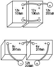
11.MULTIPLE BATTERY CHARGING
Batteries of the same voltage may be connected in parallel for maintenance charging. Charge time increases in proportion to the number of batteries. Rate of charge decreases in the same proportion.
Example: Charging 2 batteries in parallel will take 2 times longer; each battery receives 1/2 the amount of charge showing on the ammeter. Thus, if the ammeter shows a 30-amp charge, each battery will get a 15-amp charge (when batteries have the same rating, same state of charge, etc.).
12.CHARGER FEATURES AND CONTROLS
12.1DIGITAL DISPLAY BUTTON
Use this button to set the function of the digital display to one of the following:
•BATTERY %: The digital display shows an estimate of the percent of charge of the battery connected to the charger battery clamps.
•VOLTAGE: The digital display shows the voltage at the charger battery clamps in DC volts.
•ALTERNATOR %: The digital display shows an estimated percentage of the output of the vehicle charging system connected to the charger battery clamps as compared to a properly functioning system.
•10 •
12.2BATTERY TYPE SWITCH
Use this switch button to set the type of battery to be charged to one of the following:
•12v Standard: Use on typical lead-acid batteries (starting and deep cycle). This type of battery is usually used in boats, cars, trucks, and motorcycles. These batteries have vent caps and are often marked “low maintenance” or “maintenance-free”.
•12V AGM: Use on batteries marked AGM (starting or deep cycle). AGM batteries have sealed cases without vent caps.
•12V GEL CELL: Use on batteries marked GEL CELL (starting or deep cycle). Safe to use on “ALL” batteries.
•6V STANDARD: This is the type of battery usually used in antique and some specialized vehicles. The 6V Standard battery type is not selectable for batteries greater than 8.5V DC.
With the exception of AGM and GEL CELL batteries, all other battery types may or may not have vent caps. Vent caps are located on top of the battery and provide a means to add distilled water when needed. Batteries should be marked with their type. If charging a battery that is not marked, check the manual of the item that uses the battery. If the battery type is unknown, use the GEL CELL setting.
12.3CHARGING/STARTING BUTTON
Use this button to set the maximum charge rate to one of the following:
•2A SMALL BATTERY: Provides 2A for charging small batteries such as those commonly used in garden tractors, snow mobiles and motorcycles. The 2A rate is not intended to be used as a trickle charger for larger batteries.
•15A<>40A REGULAR battery: Automatically switches between 15 and 40 amps, or provides 15 amps continuous depending on the battery. Use for charging automotive batteries, marine batteries, and deep cycle batteries. Not intended for industrial applications.
•125A engine start: Provides 125 amps for cranking an engine with a weak or run down battery. Always use in combination with a battery.
•off: Charger returns to tester mode and the SMALL BATTERY, REGULAR BATTERY and ENGINE START LEDs all stay OFF.
13.ASSEMBLING YOUR CHARGER
Included with your battery charger are two cord wrap cleats for storage of the clamp cables.
To install, align the two tabs to correspond with the two receptacles and push until you hear a snap.
Wrap clamp cables after unplugging the power cord from the AC wall outlet and store your charger in a dry location.
•11 •
14.Using Engine Start
Your battery charger can be used to jump start your car if the battery is low. Follow these instructions on how to use the ENGINE START feature.
IMPORTANT: Follow all safety instructions and precautions when charging your battery. Wear complete eye protection and clothing protection. Charge your battery in a well-ventilated area.
IMPORTANT: Using the ENGINE START feature WITHOUT a battery installed in the vehicle could cause damage to the vehicle’s electrical system.
14.1.For battery connections, see page 6 and follow instructions. With the charger plugged in and connected to the battery of the vehicle, press the CHARGING/STARTING button until the ENGINE START LED is lit. Only the ENGINE START, CHARGING, CONNECTED, and VOLTAGE LEDs should be lit, unless the 6V Standard battery type has been selected. In that case, the 6V standard LED will also be lit.
14.2Crank the engine for no more than 5 seconds. If engine does not start, wait 3 minutes before cranking again.
14.3After the engine starts, unplug the power cord before disconnecting the output clamps from the battery.
14.4Clean and store the charger in a dry location.
Note: During the starting sequence listed above, the charger is set to one of three states.
14.5Wait for cranking - The charger waits until the engine is actually being cranked before delivering 125 amps for engine start. The charger delivers charge at a rate of up to 15 amps while waiting and will reset if the engine is not cranked within 15 minutes. (If the charger resets, it sets itself for a SMALL BATTERY charge and 12V Standard battery type.) While waiting for cranking, the digital display shows the battery voltage (it can’t be set to percent).
14.6Cranking - When cranking is detected, the charger will automatically deliver up to its maximum output (at least 125A) as required by the starting system for up to 5 seconds or until the engine cranking stops. The digital display shows a countdown of the remaining crank time in seconds. It starts at 5 and counts down to 0.
14.7Cool Down - After cranking, the charger enters a mandatory 3-minute (180 second) cool down state. During this period, no settings can be changed. The buttons are ignored. The digital display indicates the remaining cool down time in seconds. It starts at 180 and counts down to 0. The ENGINE START LED blinks once every second. During the cool down period, no current is delivered to the battery. After 3 minutes, the engine START LED will stop blinking and will light continuously, indicating that another crank cycle can be started. The digital display will change from displaying the countdown back to displaying the battery voltage. The CHARGING LED will then be lit.
•12 •
14.8ENGINE STARTING NOTES:
If the battery is disconnected during the cool down period, the charger will reset.
15.USING BUILT-IN BATTERY TESTER
15.1OVERVIEW
The charger has a built-in battery tester that displays either an accurate battery voltage or an estimate of the battery’s relative charge based on the battery voltage and a scale set by the Battery Council International.
15.2TESTING SEQUENCE
There are four basic steps required to use the charger as a battery tester.
1.Connect the charger battery clamps to the battery.
2.Connect the charger power cord to a 120V AC outlet.
3.If necessary, press the BATTERY TYPE button until the correct type is indicated.
4.Read the voltage on the digital display or press the digital display button to set the tester to Battery % and read the battery percent.
15.3TESTER AND CHARGER
When first turned on, the charger operates only as a tester, not as a charger. To continue to use it as only a tester, avoid pressing the
charging/starting button. Selecting a charge rate activates the battery charger and deactivates the tester. Pressing the CHARGING/ startING button when the engine start LED is lit (except during the
180second cool down) will shut off the charger and activate the tester.
15.4POWER-UP IDLE TIME LIMIT
If no button is pressed within 15 minutes after the unit is first powered up, it will automatically switch from tester to charger, if a battery is connected. In that case, the charger will be set for the 2A small battery charge rate and 12V standard battery type.
15.5TESTER WITHOUT TIME LIMIT
If either the DIGITAL Display or Battery Type button is pressed within the first 15 minutes after the unit is powered up, it will remain a tester (not a charger) indefinitely, unless a charge rate is selected.
15.6TESTING AFTER CHARGING
After the unit has been changed from tester to charger (by selecting a charge rate), it remains a charger. To change the unit back to a tester, press the CHARGING/STARTING button until all charge rate LEDs are off.
•13 •
15.7TESTER STATUS LEDs
When the charger is operating as a battery tester, the status LEDs light under the following conditions:
•The CHARGED LED will light if a charged battery is tested.
•The CHARGING LED does not light in the battery test mode.
•The connected LED lights if a properly connected battery is detected.
•When the tester digital display is set to voltage, the CHARGED and CHARGING LEDs won't light (it could be testing a battery or an alternator).
15.8INITIAL PERCENT CALCULATION
When a battery % is calculated for the first time after connecting a battery, the digital display will show three dashes (“---”) for a period as long as several seconds while the tester analyzes the battery.
15.9NOTES FOR TESTING BATTERY %
A recently charged battery could have a temporarily high voltage due to what is known as “surface charge”. The voltage of such a battery will
gradually drop during the period immediately after the charging system is disengaged. Consequently, the tester could display inconsistent values for such a battery. For a more accurate reading, the surface charge should be removed by temporarily creating a load on the battery, such as by turning on lights or other accessories.
The battery % ranges from 0 to 100.
The battery tester is only designed to test batteries. Testing a device with a rapidly changing voltage could yield unexpected or inaccurate results.
16.Using the built-in alternator tester
This battery charger has a built-in alternator tester that displays either an accurate alternator voltage or an estimate of the alternator’s relative output compared to normal alternators. The Alternator % values displayed should be taken as general reference, not precise diagnosis. The alternator tester functions the same as the battery tester (see previous section of this manual for details) with a few differences.
16.1TESTING SEQUENCE
There are three basic steps required to use the unit as an alternator tester.
1.Connect the charger battery clamps to the battery or charging system. Be sure to follow all safety precautions listed.
2.Connect the charger power cord to a 120V AC wall outlet. Again, be sure to follow all safety precautions listed.
3.Start the vehicle and turn on the vehicle’s headlights. Read the voltage on the digital display or press the digital display button to set the tester to Alternator % and read the alternator percent.
•14 •
16.2TESTER STATUS LEDs
When the unit is operating as an alternator tester, the status LEDs light under the following conditions:
•The Charged LED will light if the output of the charging system is at the normally desired level.
•The CHARGING LED does not light in the alternator test mode.
•The connected LED lights if a voltage is detected.
•When the tester display mode is set to voltage, the CHARGED and CHARGING LEDs won't light (it could be testing a battery or an alternator).
16.3ALTERNATOR TESTING NOTES
•The alternator percent display can range from 0 to 199.
•The digital display cannot be set to Alternator % during charging.
17.MAINTENANCE INSTRUCTIONS
The charger is designed and built with high quality materials requiring only a minimum amount of care.
17.1Clamps should be cleaned each time the charger is used to prevent corrosion from battery fluid.
17.2Cords should be coiled when the charger is not being used to prevent damage.
17.3Other servicing should be performed by qualified service personnel.
18.TROUBLESHOOTING
18.1The battery is connected and the charger is on, but it isn't charging.
a.The charger is in tester mode, not charger mode. Press the CHARGING/STARTING button to activate charging and select a charge rate.
18.2Indicator lights are lit in an erratic manner.
a.You might have accidentally activated a special diagnostic mode. Make sure nothing is touching the control panel, then unplug the charger and plug it in again.
b.The charger may be defective. Return to place of purchase for replacement.
•15 •
18.3The DIGITAL DISPLAY always flashes before the battery is completely charged.
a.The incorrect battery type may have been selected. Reset the charger by briefly unplugging it or briefly disconnecting the negative battery clip.
Select the desired charge rate (small or regular battery) and battery type again, if necessary.
b.This will happen if the battery did not reach full charge within 24 hours. May be due to a very large battery or a bank of batteries requiring more power than a 1540 amp charger can deliver within 24 hours. The battery may also be faulty.
18.4Engine crank time is less than specified.
a.Starter motor may be drawing more than 125 amps. Charge the battery at the REGULAR BATTERY rate for 10 to 15 minutes then crank the engine.
18.5The Charged LED lights a few minutes after connecting to the battery.
a.The battery may be fully charged or recently charged, leaving the battery voltage high enough to appear to be fully charged. If the battery is in a vehicle, turn the headlights on for a few minutes to reduce the battery voltage and try charging again.
b.The incorrect battery type may have been selected. Reset the charger by briefly unplugging it or briefly disconnecting the negative battery clip.
Select the desired charge rate (small or regular battery) and battery type again, if necessary.
• 16 •
 Loading...