

Nakamichi CD-45z Owners Manual

R
CD-45z
Mobile Receiver / CD Player
Owner’s Manual
Nakamichi Mobile Sound System

Nakamichi Mobile Sound System
Before installing or using the unit, please read
this manual carefully, to ensure correct operation.
Keep the manual at hand for future reference.
English
WARNING
TO REDUCE THE RISK OF FIRE OR ELECTRIC SHOCK, DO NOT EXPOSE THIS APPLIANCE TO RAIN OR MOISTURE.
CAUTION
- Prolonged exposure to sound at excessive levels has been proven to cause temporary and,
in some instances, permanent hearing loss. In
order to protect your hearing and your future
enjoyment of music, it is strongly recommended
that you avoid exposure to excessive listening
levels.
- For reasons of traffic safety, you should keep
the listening volume to a level which will not
mask outside noises while driving.
DANGER - Invisible laser radiation when opened
and interlock failed or defeated. Avoid direct exposure to beam.
CAUTION - Use of the controls or adjustments or
performance of procedures other than those specified herein may result in hazardous radiation exposure.
LASER DIODE PROPERTIES
MAXIMUM RADIANT POWER: 0.5 mW
WAVE LENGTH: 780 nm - 815 nm
EMISSION DURATION: CONTINUOUS
This equipment has been tested and found to comply with the limits for a Class B digital device, pursuant to part 15 of the FCC Rules. These limits are
designed to provide reasonable protection against
harmful interference in a residential installation. This
equipment generates, uses and can radiate radio
frequency energy and, if not installed and used in
accordance with the instructions, may cause harmful interference to radio communications. However,
there is no guarantee that interference will not occur
in a particular installation. If this equipment does
cause harmful interference to radio or television reception, which can be determined by turning the
equipment off and on, the user is encouraged to try
to correct the interference by one or more of the following measures:
–Reorient or relocate the receiving antenna.
– Increase the separation between the equipment
and receiver.
– Connect the equipment into an outlet on a circuit
different from that to which the receiver is connected.
– Consult the dealer or an experienced radio/TV
technician for help.
WARNING- The Federal Communications Commis-
sion does not allow any modifications or changes to
the unit EXCEPT as that specified by Nakamichi in
this manual. Failure to comply with this government
regulation could void your authority to operate the
equipment.
Complies with FDA radiation performance standards,
21 CFR Subchapter J.
Please record the Serial Number in the space provided below and retain this number.
The Serial Number is located on the top panel of the
unit.
Model Number: CD-45z
Serial Number:
Contents
Precaution ................................................... 3
Installation ................................................... 4
Connections.................................................6
External Equipment Connections ............... 7
Basic Operation Steps ................................ 8
2
CD Playback.............................................. 12
CD Changer Control..................................14
FM/AM Reception......................................16
Troubleshooting.........................................18
Specifications ............................................19
Precautions
Nakamichi Mobile Sound System
Important Notice
We thank you for your purchase of this Nakamichi
product and trust it will provide you with many years
of trouble-free performance.
Should you be using your Nakamichi product in a
country other than the one in which it was originally
purchased, we ask you note the following:
1) The appointed Nakamichi distributor for any
given country is responsible for warranty servicing only on units distributed by or through it in
that country in accordance with its applicable
warranty.
2) Should a Nakamichi product require servicing in
a country other than the one in which it was originally purchased, the end user may seek to have
repairs performed by the nearest Nakamichi distributor, subject to that distributor's local servicing policies, but all costs of repair (parts, labor,
transportation) must be born by the owner of the
Nakamichi product.
Thank you again for your purchase.
Nakamichi Corporation
Tokyo, Japan
- Thisunitisdesigned foruse in cars with 12V
negativegroundsystemsonly.
- Donotusetheunitwhilethecar'sengineisnot
running,topreventdrainingthecarbattery.
- Ifafusehasblown,checkwhetherall connec-
tionsarecorrect,andreplacethefuseonlywith
afuseofidenticaltypeandrating.
- Whenaclosedcarisparkedinthesun,thetem-
peratureinsidethecarcanreachveryhighlevels.Ifacarisparkedoutdoorsinwinter,itmay
cooldownconsiderably.Insuchcases,usethe
unitonlyaftertheinteriortemperatureofthecar
hasreturnedtonormal.
- Donotattempttoopentheunitormakeanyin-
ternalalterations,sincethisinvolvestheriskof
damageandwillvoidthewarranty.Alsopayattentionthatnoforeignobjectsentertheunit.
- Cleantheunitonlybywiping it witha soft, dry
cloth.Avoidusingsolventsoralcohol-based
cleaners.
- Donotleavetheremote control unit ina locationthatmaybeexposedtodirectsunlight,rain,
orsplashesofwater.Otherwisedeformationor
damagemayoccur.
On CDs
- Never use any CD player accessories such as
disc adapters, disc stabilizers, disc protectors,
etc.
-Use only discs with a
which indicates compliance with official Compact Disc standards.
-Do not use discs which are not round, such as
novelty discs with octagonal or heart shape,
because this may lead to damage.
- Some CDs may have a certain amount of flash
(flaky plastic deposit resulting from the grinding process) near the center hole or the outer
circumference. Remove any such remnants
before using the disc, otherwise it may not be
possible to eject the CD properly, or skipping
may occur.
- CDs bearing labels or stickers with excess glue
around the edges or CDs with glue residue
from removed adhesive tape, stickers or similar may give problems during eject or cause
other damage.
- CD-R discs (recordable CDs) cannot be played
on this unit.
mark or similar,
English
3
Nakamichi Mobile Sound System
Installation
English
Installation should be performed by an authorized professional installer.
Please consult your dealer regarding details.
Avoid locations which may be exposed to:
- direct sunlight
- hot air from heater outlets
-rain or moisture
-high levels of dust
- high levels of vibration
Verify that the supplied accessories are complete:
-Mounting sleeve .......................................... (1)
- Metal stay .................................................... (1)
-M5 hex screw .............................................. (4)
-M5 flat cross-recess screw ......................... (4)
-M5 spring washer........................................ (5)
-M5 washer................................................... (5)
- M5 nut.......................................................... (1)
-M5 fastening screw ..................................... (1)
-Masking tape
(for sealing off clearances in the installation location)
-Trim panel rim ............................................. (1)
- Rubber bushing........................................... (1)
- 14-pin connector ......................................... (1)
- 10A spare fuse (for battery) ........................ (1)
- Remote control unit..................................... (1)
-IEC R03 (size AAA) battery
(for remote control) ..................................... (2)
- Hook-and-loop fastener strips
(for remote control) ................ (hook 1, loop 2)
-Front panel carrying case ........................... (1)
Precaution concerning side fastening holes
When installing the unit using the side or rear
fastening holes, make sure that the fastening
screws are not longer than M5x8 (mm). Never
use longer screws, because this can cause internal damage to the unit!
Installation angle
Keep the installation angle of the unit within the
following range: horizontal (0 degrees) to slight
upwards inclination (+30 degrees). If the unit is
mounted at a different angle, sound quality may
be impaired or damage may occur.
(4)
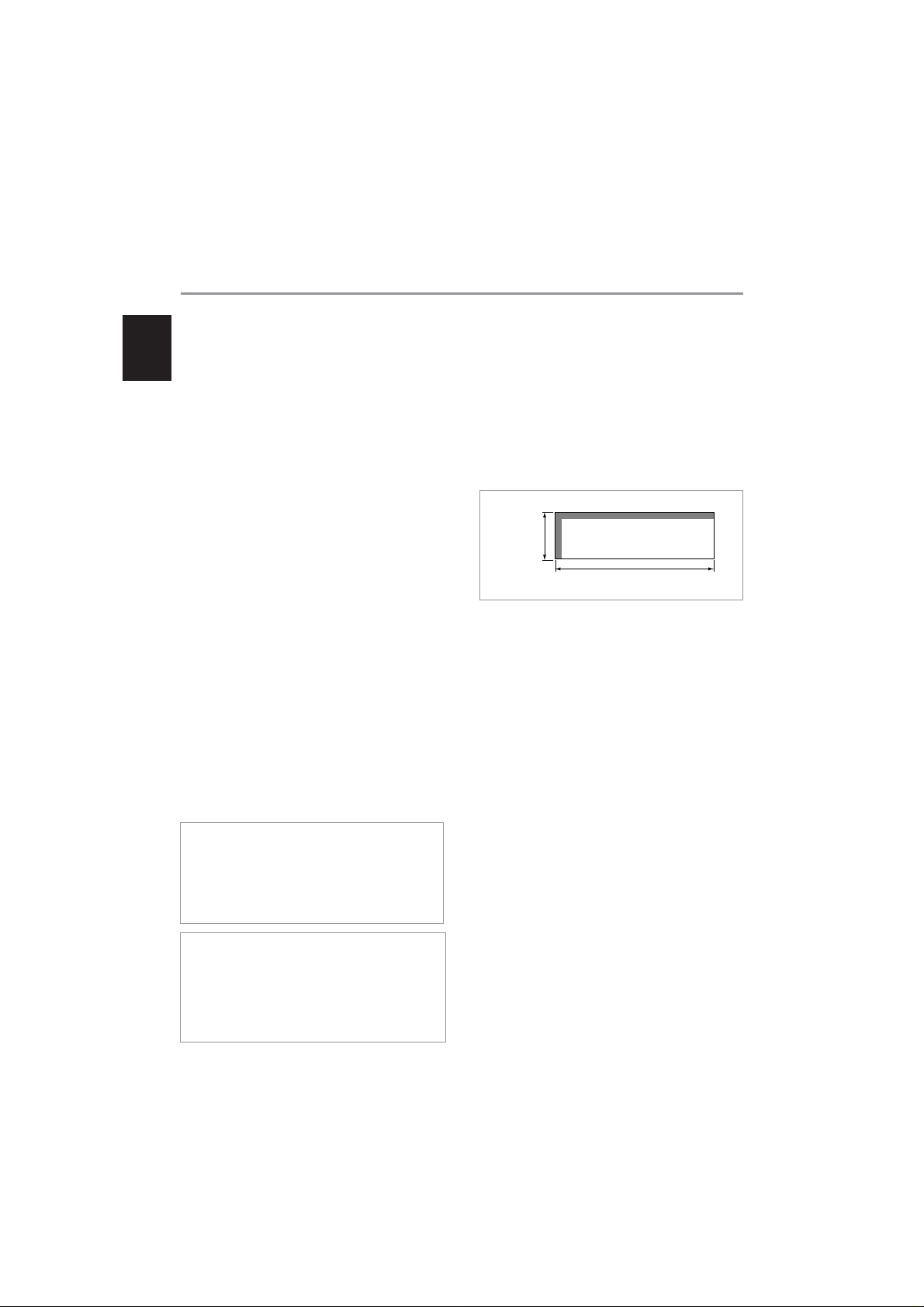
Dashboard installation
The dimensions of this unit correspond to the DIN
standard. If the dashboard of the car provides a
DIN-sized mounting slot, installation can be accomplished very easily, using the supplied mounting
sleeve. If the mounting cutout is smaller than the
standard DIN size, it must be enlarged to the following dimensions: Height 53 mm (2-3/32") x Width
182 mm (7-11/64")
53 mm
(2-3/32")
182 mm (7-11/64")
1. Insert the supplied mounting sleeve into the
mounting slot.
2. Bend the flanges of the mounting sleeve with a
screwdriver to fasten it. (Fig. A)
3. Fasten the sleeve lock plates to both sides of
the unit. If the mounting has sufficient depth,
use the long sleeve lock plates, otherwise use
the short sleeve lock plates.
4. Make sure that the mounting sleeve is securely
fixed, then install the main unit.
5. Use the supplied M5 fastening screw and metal
stay to fasten the rear section of the main unit
to the car. If a suitable support is provided inside
the mounting slot, the rubber bushing can be
used instead of the metal stay. (Fig. B)
6. After the unit is securely fixed, attach the
supplied trim panel rim. (Fig. C)
7. To remove the unit, remove the trim panel rim
and the metal stay (if it was used for rear
support of the unit). Then insert the two
screwdrivers(-) into the grooves on the left and
right of the unit and pull it out (Fig. D), taking
care not to damage the wiring on the rear.
4
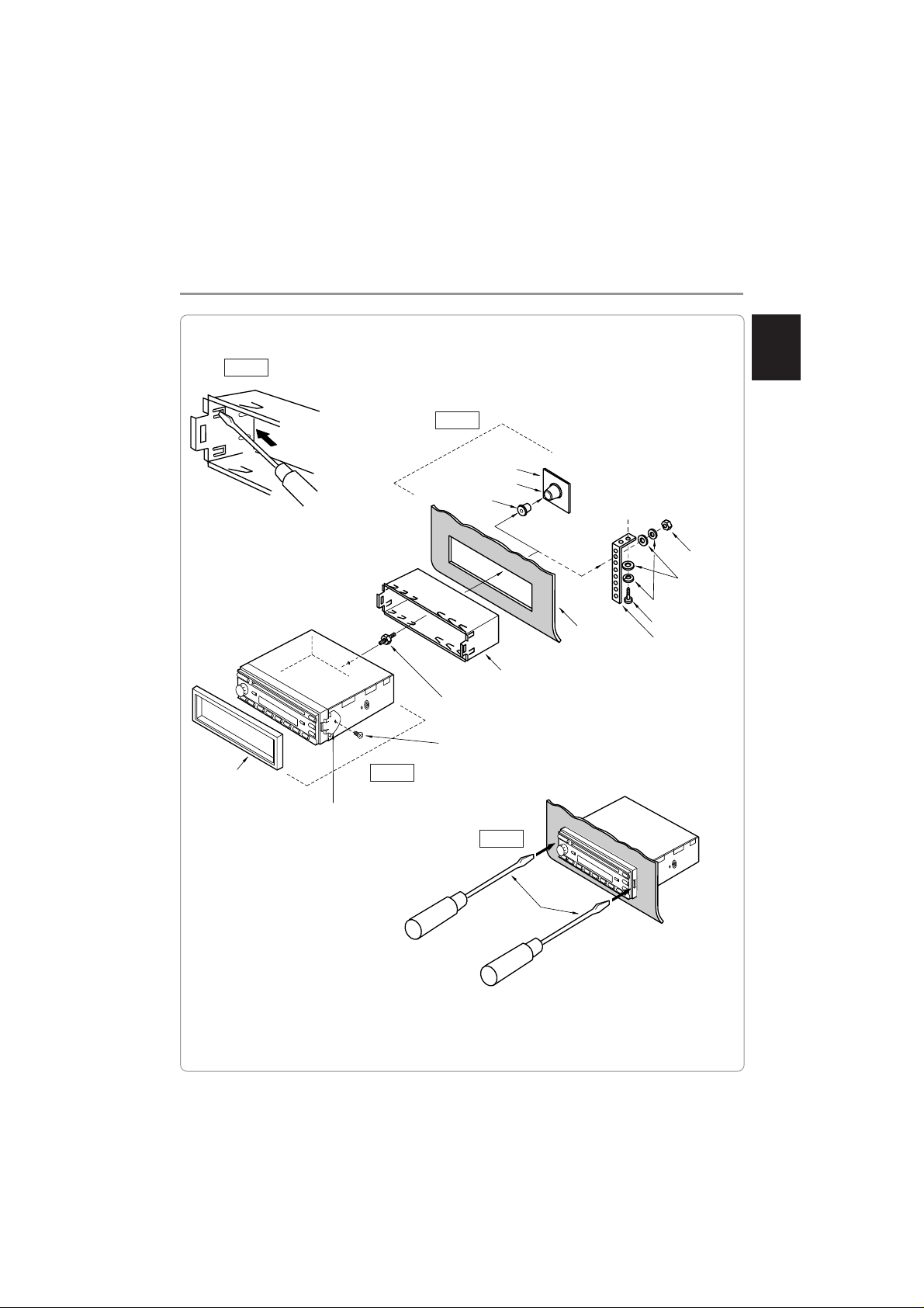
Fig. A
Fig. B
Rubber bushing
Nakamichi Mobile Sound System
Firewall
Support
M5 spring washer
Dashboard
Sheet metal screw
Metal stay
English
M5 nut
M5 washer
Panel rim
Sleeve lock plate
Fig. C
Mounting sleeve
M5 Fastening screw
(Use short side on unit)
M5 flat head screw
Fig. D
Screwdriver(-)
5
Nakamichi Mobile Sound System
Connections
English
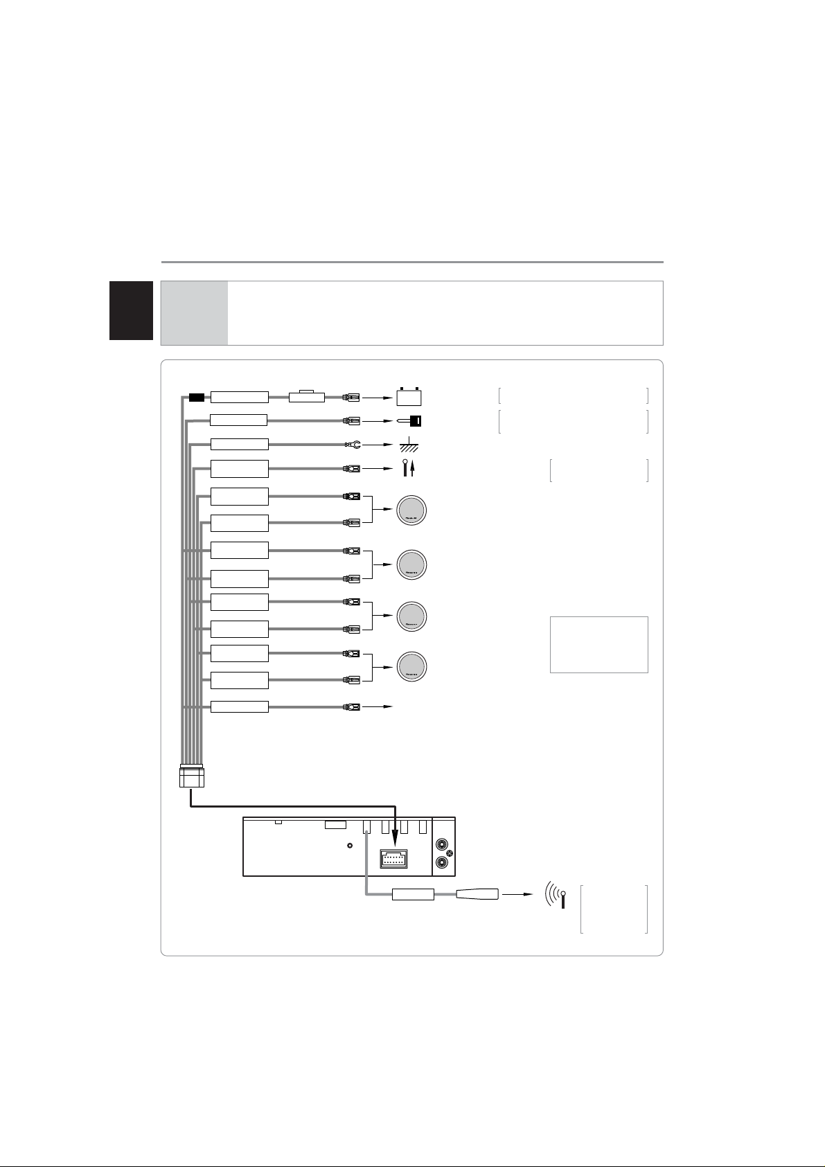
WARNING
This unit is designed for use in cars with 12 V negative ground systems only.
Be sure to remove the negative (-) terminal from your car battery before making any
connections, to prevent damage due to short-circuiting.
BATTERY (+)
ACC (+)
GROUND
P.ANT
200mA MAX
FRONT L
(+) SP
FRONT L
(-) SP
FRONT R
(+) SP
FRONT R
(-) SP
REAR L
(+) SP
REAR L
(-) SP
REAR R
(+) SP
REAR R
(-) SP
REMOTE
FUSE 10A
Yellow
Red
Black
Blue
White
White/Black
Gray
Gray/Black
Green
Green/Black
Purple
Purple/Black
Blue/White
To car battery
+
(+) terminal
To ACC circuit
To metal part on car chassis
To remote control circuit of
power antenna
To front speakers (L)
To front speakers (R)
To rear speakers (L)
To rear speakers (R)
To remote switching input of power amplifier (refer to page 7).
Connect to the positive lead of a circuit
that is constantly powered.
Connect to an accessory circuit that is
powered when the ignition key is set to
ACC.
In tuner mode, the antenna
will be automatically raised
and lowered.
Note
Do not connect the speaker
outputs of this unit to powered loudspeakers or similar, since this can lead to
noise.
14-pin
connector
ANTENNA
IMPEDANCE
75Ω
M5X8mm
MAX
F.OUT
L
R
Car antenna
ANT
In car with a diversity antenna
system, connect
the main antenna to this
jack.
6
 Loading...