

NAIS TQ2SS-L2-9V-Z, TQ2SS-L2-9V-X, TQ2SS-L2-9V, TQ2SS-L2-6V-X, TQ2SS-L2-6V-Z Datasheet
...
140
TQ-SMD
RELAYS
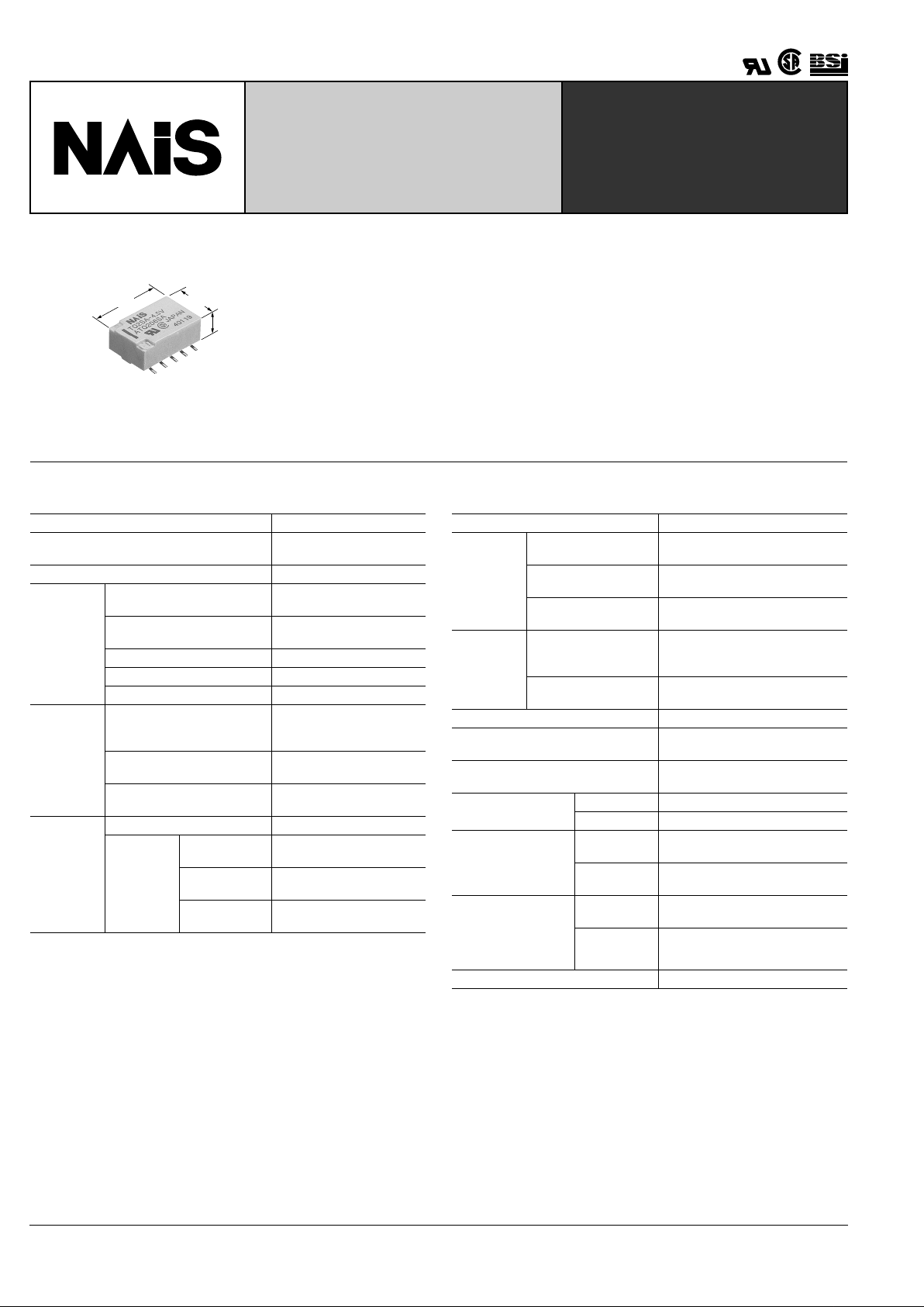
LOW-PROFILE
SURFACE-MOUNT RELAY
TESTING
mm inch
5.6
.220
9
.354
14
.551
FEATURES
• Low-profile: 6 mm .236 inch in height comforming to EIA standards
(Tape height: max. 6.5 mm .256 inch )
• Tape and reel package is available as standard packing style
• Surge withstand between contacts and coil: 2,500 V
• Breakdown voltage between contacts and coil: 1,500 V
• High capacity: 2 A
• High sensitivity:
2 Form C; 140 mW power consumption (Single side stable type)
SPECIFICATIONS
Contact
Note:
❇
1This value can change due to the switching frequency, en vironmental conditions,
and desired reliability level, therefore it is recommended to chec k this with the actual load.
Remarks
* Specifications will vary with foreign standards certification ratings.
*
1
Measurement at same location as "Initial breakdown voltage" section.
*
2
By resistive method, nominal voltage applied to the coil; contact carrying current:
2 A.
*
3
Nominal voltage applied to the coil, excluding contact bounce time.
*
4
Nominal voltage applied to the coil, excluding contact bounce time without diode.
*
5
Half-wave pulse of sine wave: 6 ms; detection time: 10 µ s
*
6
Half-wave pulse of sine wave: 6 ms
*
7
Detection time: 10 µ s
*
8
Refer to 4. Conditions f or operation, transport and storage mentioned in Cautions
for use (Page 178).
Characteristics
Arrangement 2 Form C
Initial contact resistance, max.
(By voltage drop 6 V DC 1 A)
75 m Ω
Contact material Gold-clad silver alloy
Rating
Nominal switching capacity
(resistive load)
2 A 30 V DC,
0.5 A 125 V AC
Max. switching power
(resistive load)
60 W, 62.5 VA
Max. switching voltage 220 V DC, 125 V AC
Max. switching current 2 A
Min. switching capacity ❇ 1 10 µ A 10 mV DC
Nominal
operating
power
Single side stable
140 mW (1.5 to 12 V DC)
200 mW (24 V DC)
300 mW (48 V DC)
1 coil latching
70 mW (1.5 to 12 V DC)
100 mW (24 V DC)
2 coil latching
140 mW (1.5 to 12 V DC)
200 mW (24 V DC)
Expected
life (min.
operations)
Mechanical (at 180 cpm) 10
8
Electrical
(at 20 cpm)
2 A 30 V DC
resistive
10
5
1 A 30 V DC
resistive
2 × 10
5
0.5 A 125 V AC
resistive
10
5
Initial insulation resistance*
1
Min. 1,000 M Ω (at 500 V DC)
Initial
breakdown
voltage
Between open
contacts
1,000 Vrms for 1 min.
(Detection current: 10 mA)
Between contact sets
1,500 Vrms for 1 min.
(Detection current: 10 mA)
Between contact and
coil
1,500 Vrms for 1 min.
(Detection current: 10 mA)
Initial surge
voltage
Between open
contacts
(10 × 160 µ s)
1,500 V (FCC Part 68)
Between contacts and
coil (2 × 10 µ s)
2,500 V (Bellcore)
Temperature rise*
2
(at 20 ° C) Max. 50 ° C
Operate time [Set time]*
3
(at 20 ° C)
Max. 4 ms (Approx. 2 ms)
[Max. 4 ms (Approx. 2 ms)]
Release time [Reset time]*
4
(at 20 ° C)
Max. 4 ms (Approx. 1 ms)
[Max. 4 ms (Approx. 2 ms)]
Shock resistance
Functional*
5
Min. 750 m/s
2
{75 G}
Destructive*
6
Min. 1,000 m/s
2
{100 G}
Vibration resistance
Functional*
7
200 m/s
2
{20G}, 10 to 55 Hz
at double amplitude of 3.3 mm
Destructive
294 m/s
2
{30G}, 10 to 55 Hz
at double amplitude of 5 mm
Conditions for operation, transport and
storage*
8
(Not freezing and condensing
at low temperature)
Ambient
temperature
–40 ° C to +85 ° C*
3
–40 ° F to +185 ° F
Humidity 5 to 85% R.H.
Unit weight Approx. 2 g .071 oz
TQ-SMD
141
ORDERING INFORMATION
2 SA L 3V ZEx. TQ
Contact arrangement Surface-mount availability Operating function Coil voltage (DC)
Packing style
SA: Standard surface-mount
SA: terminal type
SL: High connection reliability
SA: surface-mount terminal type
SS: Space saving surface-
SA: mount terminal type
2: 2 Form C Nil: Single side stable
L: 1 coil latching
L2: 2 coil latching
1.5, 3, 4.5, 5, 6,
9, 12, 24, 48* V
Nil: Tube packing
Z: Tape and reel packing (picked from the 6/7/8/9/10-pin side)
*48 V coil type: Single side stable only
Notes: 1. Tape and reel (picked from 1/2/3/4/5-pin side) is also available by request. Part No. suffix “-X” is needed when ordering. (ex.) TQ2SA-3V-X
2. Tape and reel packing symbol “-Z” or “-X” are not marked on the relay.
–– –
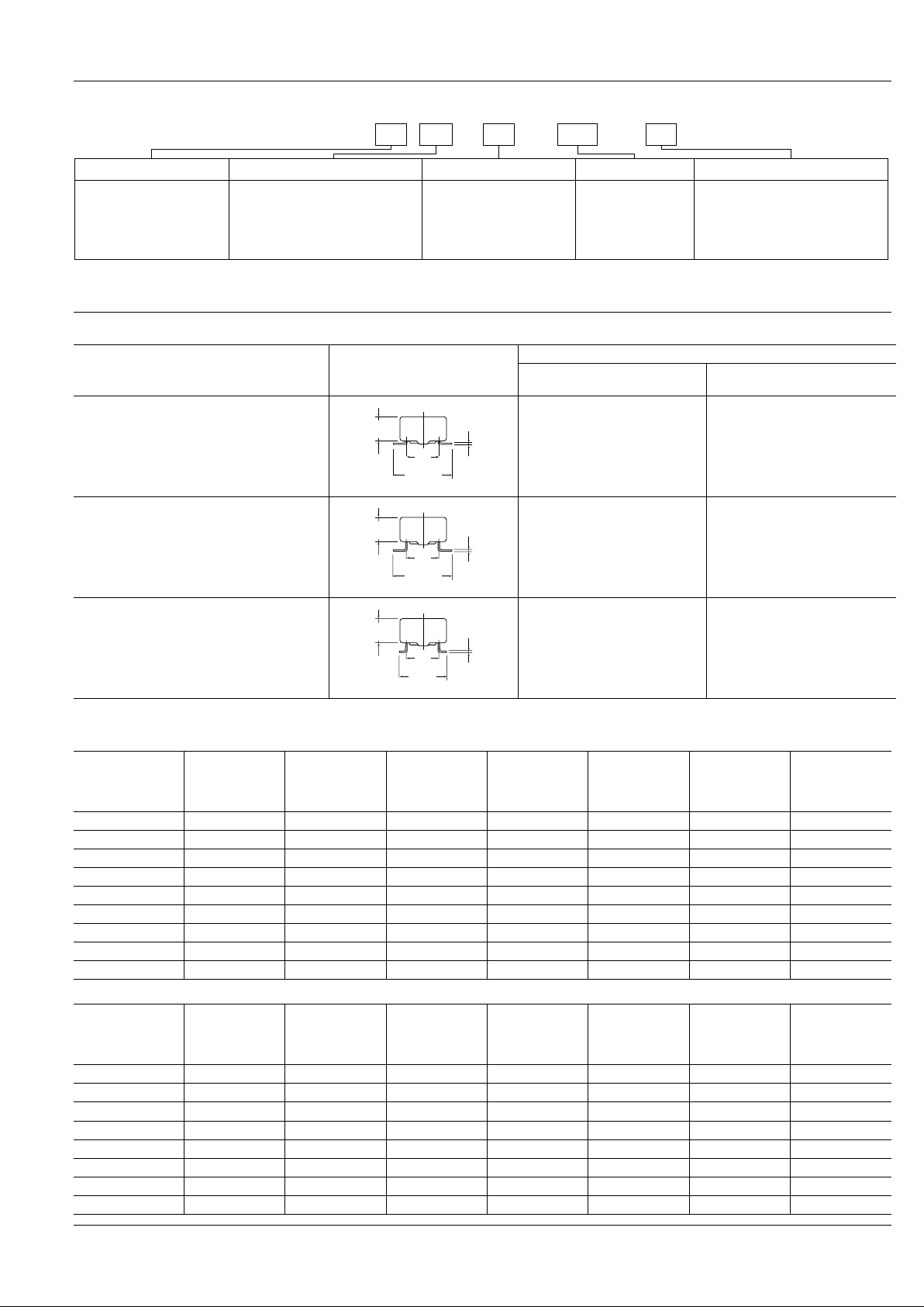
Surface-mount terminal variation
Variation Terminal style
Ambient environment
Normal environments
(indoor)
Drastic temperature fluctuations
(outdoor)
SA type
(Standard surface-mount terminal type)
Recommended —
SL type
(Highly connection reliability surface-mount
terminal type)
Recommended Recommended
SS type
(Space saving surface-mount terminal type)
Recommended Recommended
7.62
.300
11.5±0.5
.453±.020
4.9
.193
0.25
.010
7.62
.300
11.5±0.5
.453±.020
4.9
.193
0.25
.010
7.62
.300
9.3±0.5
±.020
4.9
.193
0.25
.010
TYPES
1. Single side stable
2. 1 coil latching
Part No.
Nominal
voltage,
V DC
Pick-up voltage,
V DC (max.)
Drop-out
voltage,
V DC (min.)
Nominal
operating
current,
mA ( ± 10%)
Coil resistance,
Ω ( ±
10%)
Nominal
operating power ,
mW
Max. allowable
voltage,
V DC
TQ2S ❍ -1.5 V 1.5 1.13 0.15 93.8 16 140 2.2
TQ2S ❍ -3 V 3 2.25 0.3 46.7 64.3 140 4.5
TQ2S ❍ -4.5 V 4.5 3.38 0.45 31 145 140 6.7
TQ2S ❍ -5 V 5 3.75 0.5 28.1 178 140 7.5
TQ2S ❍ -6 V 6 4.5 0.6 23.3 257 140 9
TQ2S ❍ -9 V 9 6.75 0.9 15.5 579 140 13.5
TQ2S ❍ -12 V 12 9 1.2 11.7 1,028 140 18
TQ2S ❍ -24 V 24 18 2.4 8.3 2,880 200 36
TQ2S ❍ -48 V 48 36 4.8 6.3 7,680 300 57.6
Part No.
Nominal
voltage,
V DC
Set voltage,
V DC (max.)
Reset voltage,
V DC (max.)
Nominal
operating
current,
mA ( ± 10%)
Coil resistance,
Ω ( ±
10%)
Nominal
operating power ,
mW
Max. allowable
voltage,
V DC
TQ2S ❍ -L-1.5 V 1.5 1.13 1.13 46.9 32 70 2.2
TQ2S ❍ -L-3 V 3 2.25 2.25 23.3 128.6 70 4.5
TQ2S ❍ -L-4.5 V 4.5 3.38 3.38 15.6 289.3 70 6.7
TQ2S ❍ -L-5 V 5 3.75 3.75 14 357 70 7.5
TQ2S ❍ -L-6 V 6 4.5 4.5 11.7 514 70 9
TQ2S ❍ -L-9 V 9 6.75 6.75 7.8 1,157 70 13.5
TQ2S ❍ -L-12 V 12 9 9 5.8 2,057 70 18
TQ2S ❍ -L-24 V 24 18 18 4.2 5,760 100 36
 Loading...