

NAIS SF2D-DC12V, SF2D-DC24V, SF2D-DC48V, SF2D-DC60V, SF4D-DC12V Datasheet
...
(pending)
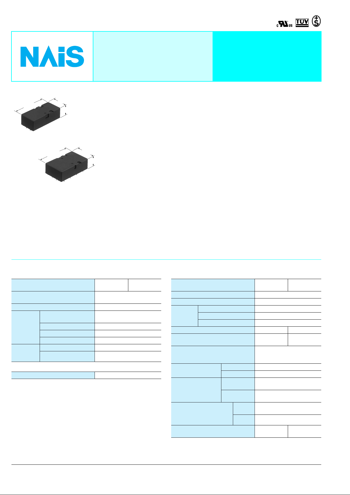
53.3±0.3
2.098±.012
2 Form A 2 Form B
53.3±0.3
2.098±.012
4 Form A 4 Form B
25.0
.984
16.5±0.5
.650±.020
POLARISED, MONOSTABLE
SAFETY RELAY
FEATURES
• High contact reliability
High contact reliability is achieved through
the use of a double contact.
• Forced operation contacts
(2 Form A 2 Form B)
N.O. and N.C. side contacts are
connected through a card so that one
33±0.5
1.299±.020
16.5±0.5
.650±.020
mm inch
interacts with the other in movement. In
case of a contact welding, the other keeps
a min. 0.5mm .020inch contact gap.
• Independent operation contacts
(4 Form A 4 Form B)
There are 4 points of forced operation
contacts.
Each pair of contacts is free from the main
armature and is independent from each
other. So if a N.O. pair of contacts are
welded, the other 3 N.O. contacts are not
effected (operate properly) That enables
to plan a circuit to detect welding or go
back to the beginning condition.
SF-RELAYS
Double contact
• Separated chamber structure (2 Form
A 2 Form B, 4 Form A 4 Form B)
N.O. and N.C. side contacts are put in
each own space surrounded with a card
and a body-separater. That prevents short
circuit between contacts, which is caused
by their springs welding or damaged.
• High breakdown voltage 2,500 Vrms
between contacts and coil
• High sensitivity
Realizes thin shape and high sensitivity
(500 mW nominal operating power) by
utilizing high-efficiency polarized
magnetic circuit with 4-gap balanced
armature.
• Complies with safety standards
Standard products are UL, CSA, TÜV and
SEV certified. Comform to European
standards. TÜV certified (945/EL, 178/
88). Complies with SUVA European
standard.
SPECIFICATIONS
Contact
Contact arrangement
Initial contact resistance, max.
(By voltage drop 6 V DC 1 A)
Contact material Gold-flashed silver alloy
Nominal switching
Rating
(resistive)
Expected
life (min.
operations)
capacity
Max. switching power 1,500 VA, 180 W
Max. switching voltage 440 V AC, 30 V DC
Max. carrying current 6 A
Mechanical (at 180 cpm) 10
Electrical (at 20 cpm) 10
2 Form A
2 Form B
6 A 250 V AC, 6 A 30 V DC
Coil
Nominal operating power 500 mW
Remarks
* Specifications will vary with foreign standards certification ratings.
1
Measurement at same location as “Initial breakdown voltage” section
*
*2Detection current: 10mA
3
Excluding contact bounce time
*
*4Half-wave pulse of sine wave: 11ms; detection time: 10µs
*5Half-wave pulse of sine wave: 6ms
*6Detection time: 10µs
7
Refer to 6. Usage, transport and storage mentioned in NOTES
*
30 m
4 Form A
4 Form B
Ω
7
5
Characteristics
Contact arrangement
Max. operating speed 180 cpm (at nominal voltage)
Initial insulation resistance*
Initial
breakdown
voltage*
Operate time*
Release time (without diode)*
(at nominal voltage)
Temperature rise (at nominal voltage)
(at 20°C)
Shock resistance
Vibration resistance
Conditions for operation,
transport and storage*
freezing and condensing at
low temperature)
Unit weight
Between open contacts 1,300 Vrms
Between contact sets 2,500 Vrms
2
Between contact and coil 2,500 Vrms
3
(at nominal voltage) Approx. 17 ms Approx. 18 ms
1
3
Functional*
Destructive*
Functional*
Destructive
Ambient
7
(Not
temp.
Humidity 5 to 85% R.H.
2 Form A
2 Form B
Min. 1,000 MΩ at 500 V DC
Approx. 7 ms Approx. 6 ms
with nominal coil voltage and
4
5
6
38 g 1.34 oz
Max. 45°C
at 6 A carry current
Min. 294 m/s2 {30 G}
Min. 980 m/s2 {100 G}
10 to 55 Hz at double
amplitude of 2 mm
10 to 55 Hz at double
amplitude of 2 mm
–40°C to +70°C
–40°F to +158°F
Approx.
4 Form A
4 Form B
Approx.
47 g 1.66 oz
4
ORDERING INFORMATION
Ex. SF 2 D DC 5 V
Contact arrangement Coil voltage
DC 5, 12, 24, 48, 60 V2: 2 Form A 2 Form B
4: 4 Form A 4 Form B
UL/CSA, TÜV, SEV approved type is standard
TYPES AND COIL DATA (at 20°C 68°F)
Contact
arrangement
2 Form A
2 Form B
4 Form A
4 Form B
Part No.
Nominal
voltage, V DC
SF2D-DC5V 5 3.75 0.5 50 100 500 6
SF2D-DC12V 12 9 1.2 288 41.7 500 14.4
SF2D-DC24V 24 18 2.4 1.152 20.8 500 28.8
SF2D-DC48V 48 36 4.8 4.608 10.4 500 57.6
SF2D-DC60V 60 45 6.0 7.200 8.3 500 72
SF4D-DC5V 5 3.75 0.75 50 100 500 6
SF4D-DC12V 12 9 1.8 288 41.7 500 14.4
SF4D-DC24V 24 18 3.6 1.152 20.8 500 28.8
SF4D-DC48V 48 36 7.2 4.608 10.4 500 57.6
SF4D-DC60V 60 45 9.0 7.200 8.3 500 72
Pick-up
voltage, VDC
(max.)
voltage, V DC
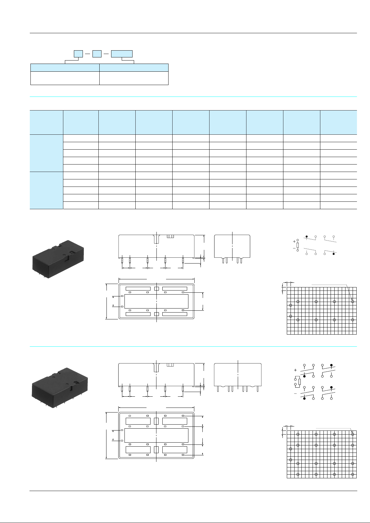
DIMENSIONS
1. 2 Form A 2 Form B
12.7
12.7
12.7
25.0
.984
7.62
.300
5.08
.200
.500
53.3±0.3
2.098±.012
6587
1
2
109
.500
.500
TYPICAL APPLICATIONS
• Industrial equipment such as presses and machine tools
Drop-out
(min.)
.630±.020
3.0±0.5
.118±.020
1211
Coil resistance
16±0.5
0.5
.020
12.7
.500
Ω
(±10%)
Nominal
operating
current,
mA (±10%)
Nominal
operating
power, mW
Schematic (Bottom view)
5
1
2
9 101112
PC board pattern (Bottom view)
2.54
10-.055 DIA. HOLES
2.54
.100
.100
Max. allow able
voltage, V DC
mm inch
678
10-1.4 DIA. HOLES
2. 4 Form A 4 Form B
33±0.5
1.299±.020
7.62
.300
5.08
.200
General tolerance: ±0.3 ±.012
Tolerance: ±0.1 ±.004
Schematic (Bottom view)
13
14615716
16±0.5
.630±.020
0.3
.012
3.0±0.5
12.7
12.7
12.7
.500
.500
53.3±0.3
2.098±.012
1413 1615
65
1
2
109
1817 2019
.500
.118±.020
87
1211
7.62
.300
12.7
.500
7.62
.300
2.54
.100
1
5
9171018111912
2
8
20
PC board pattern (Bottom view)
2.54
.100
18-1.4 DIA. HOLES
18-.055 DIA. HOLES
General tolerance: ±0.3 ±.012
Tolerance: ±0.1 ±.004
5
 Loading...