

NAIS SF2-DC12V, SF2-DC18V, SF2-DC21V, SF2-DC24V, SF2-DC36V Datasheet
...
SF
π
53.3±0.3
2.098±.012
53.3±0.3
2.098±.012
53.3±0.3
2.098±.012
25.0
.984
16.5±0.3
.650±.012
33±0.3
1.299±.012
16.5±0.3
.650±.012
POLARISED, MONOSTABLE
SAFETY RELAY with
(mechanical linked) forced
contacts operation
FEATURES
• Forced operation contacts (2 Form A
2 Form B, 3 Form A 1 Form B)
25.0
.984
16.5±0.3
.650±.012
mm inch
N.O. and N.C. side contacts are
connected through a card so that one
interacts with the other in movement. In
case of a contact welding, the other
keeps a min. 0.5mm .020inch contact
gap.
• Independent operation contacts
(4 Form A 4 Form B)
Each pair of contacts is free from the
main armature and is independent from
each other. So if a N.O. pair of contacts
are welded, the other 3 N.O. contacts are
not effected (operate properly) That
(SF3 pending) (SF3 pending) (SF3 pending)
SF-RELA YS
enables to plan a circuit to detect welding
or go back to the beginning condition.
• Separated chamber structure
(2 Form A 2 Form B, 3 Form A 1 Form B,
4 Form A 4 Form B)
N.O. and N.C. side contacts are put in
each own space surrounded with a card
and a body-separater. That prevents
short circuit between contacts, which is
caused by their springs welding or
damaged.
• UL/CSA, TÜV, SEV approved
(UL/CSA, SEV of SF3 pending)
SPECIFICATIONS
Contact
Type SF2 SF3 SF4
Arrangement
2 Form A
2 Form B
Initial contact resistance, max.
(By voltage drop 6 V DC 1 A)
Contact material Gold-flashed silver alloy
Rating
(resistive)
Nominal switching
capacity
Max. switching power 1,500 VA, 180 W
Max. switching voltage 30 V DC, 440 V AC
6 A 250 V AC, 6 A 30 V DC
Max. carrying current 6 A DC, AC
Expected
life (min.
operations)
Coil (at 25°C
Mechanical (at 180
cpm) (resistive)
Electrical (at 20 cpm)
77°F
)
Nominal operating power 500 mW
Remarks
* Specifications will vary with foreign standards certification ratings.
*1
More than 10
side of contact pairs of each Form A contact and Form B contact
*2
Measurement at same location as " Initial breakdown voltage " section
*3
Detection current: 10mA
*4
Excluding contact bounce time
*5
Half-wave pulse of sine wave: 11ms; detection time: 10 µ s
*6
Half-wave pulse of sine wave: 6ms
*7
Detection time: 10 µ s
*8
Refer to 5. Conditions for operation, transport and storage mentioned in
AMBIENT ENVIRONMENT (Page 61).
5
operations when applying the nominal switching capacity to one
3 × 10
3 Form A
1 Form B
30 m Ω
7
10
4
1
*
4 Form A
4 Form B
10
Characteristics (at 25°C
77°F
, 50% Relative humidity)
SF2 SF3 SF4
Max. operating speed 180 cpm (at nominal voltage)
Initial insulation resistance*
2
Between contact sets
Initial breakdown voltage*
Between open
3
contacts
Between con-
tact and coil
Operate time*
4
(at nominal voltage)
Release time (without diode)*
(at nominal voltage)
5
Temperature rise
(at nominal voltage)
Shock
resistance
Vibration
resistance
Conditions for operation, transport and
8
storage*
(Not freezing and
condensing at low
temperature)
Functional*
Destructive*
Functional*
Destructive
Ambient
temp.
Humidity 5 to 85% R.H.
5
7
Min. 1,000 M Ω at 500 V DC
2,500 Vrms
2,500 Vrms
2,500 Vrms
Approx. 17 ms Approx. 18 ms
4
Approx. 7 ms Approx. 6 ms
Max. 45 ° C with nominal coil voltage
and at 6 A switching current
2
{30 G}
2
{100 G}
2
{12 G}, 10 to 55 Hz
5
Min. 294 m/s
Min. 980 m/s
117.6 m/s
at double amplitude of 2 mm
2
117.6 m/s
{12 G}, 10 to 55 Hz
at double amplitude of 2 mm
–40 ° C to +70 ° C –40°F to +158°F
Unit weight 37 g 1.31 oz 47 g 1.66 oz
ORDERING INFORMATION
Ex. SF 2 DC 12 V
Contact arrangement Coil voltage
2: 2 Form A 2 Form B
3: 3 Form A 1 Form B
4: 4 Form A 4 Form B
UL/CSA, TÜV, SEV approved type is standard (SF2, SF4)
TÜV approved type is standard (SF3)
258
DC 5, 9, 12, 18, 21,
24, 36, 48, 60 V
TYPICAL APPLICATIONS
• Signal
• Escalator
• Elevator
• Medical Instruments
• Railway
• Factory Automation
Ω ( ±
TYPES AND COIL DATA (at 20°C 68°F)
Contact
arrangement
SF2
SF3
SF4
Part No.
Nominal
voltage, V DC
Pick-up
voltage, VDC
(max.)
SF2-DC5V 5 3.75 0.5 50 100 500 6
SF2-DC9V 9 6.75 0.9 500 10.8
SF2-DC12V 12 9 1.2 288 41.7 500 14.4
SF2-DC18V 18 13.5 1.8 500 21.6
SF2-DC21V 21 15.75 2.1 500 25.2
SF2-DC24V 24 14.4 2.4 1.152 20.8 500 28.8
SF2-DC36V 36 27 3.6 500 43.2
SF2-DC48V 48 36 4.8 4.608 10.4 500 57.6
SF2-DC60V 60 45 6.0 7.200 8.3 500 72
SF3-DC5V 5 3.75 0.5 50 100 500 6
SF3-DC9V 9 6.75 0.9 500 10.8
SF3-DC12V 12 9 1.2 288 41.7 500 14.4
SF3-DC18V 18 13.5 1.8 500 21.6
SF3-DC21V 21 15.75 2.1 500 25.2
SF3-DC24V 24 14.4 2.4 1.152 20.8 500 28.8
SF3-DC36V 36 27 3.6 500 43.2
SF3-DC48V 48 36 4.8 4.608 10.4 500 57.6
SF3-DC60V 60 45 6.0 7.200 8.3 500 72
SF4-DC5V 5 3.75 0.75 50 100 500 6
SF4-DC9V 9 6.75 0.9 500 10.8
SF4-DC12V 12 9 1.8 288 41.7 500 14.4
SF4-DC18V 18 13.5 1.8 500 21.6
SF4-DC21V 21 15.75 2.1 500 25.2
SF4-DC24V 24 14.4 3.6 1.152 20.8 500 28.8
SF4-DC36V 36 27 3.6 500 43.2
SF4-DC48V 48 36 7.2 4.608 10.4 500 57.6
SF4-DC60V 60 45 9.0 7.200 8.3 500 72
Drop-out
voltage, V DC
(min.)
Coil
resistance
10%)
Nominal
operating
current,
mA( ± 10%)
Nominal
operating
power, mW
SF
Max. allowable
voltage, V DC
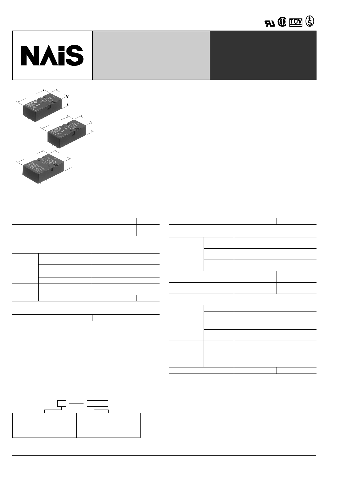
DIMENSIONS
1) SF2
25.0
.984
7.62
.300
5.08
.200
12.7
12.7
.500
.500
53.3±0.3
2.098±.012
6587
1
2
109
General tolerance: ±0.3 ±.012
12.7
.500
3.5±0.3
.138±.012
1211
16±0.3
.630±.012
0.5
.020
12.7
.500
Schematic (Bottom view)
5
1
2
678
9 101112
PC board pattern (Bottom view)
10-1.4 DIA. HOLES
2.54
10-.055 DIA. HOLES
2.54
.100
.100
Tolerance: ±0.1 ± .004
mm
inch
259
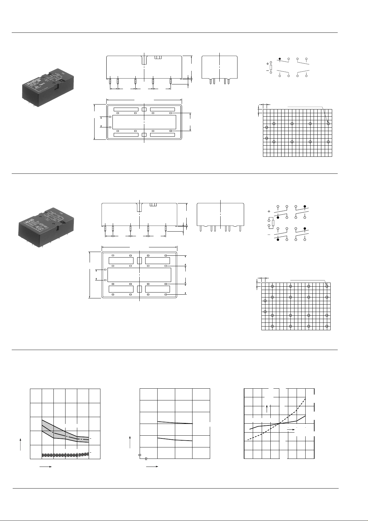
SF
-40 -20 0
20
40 60 80
-50
100
50
-100
Rate of
change, %
Ambient
temperature, °C
Pick-up
voltage
Drop-out
voltage
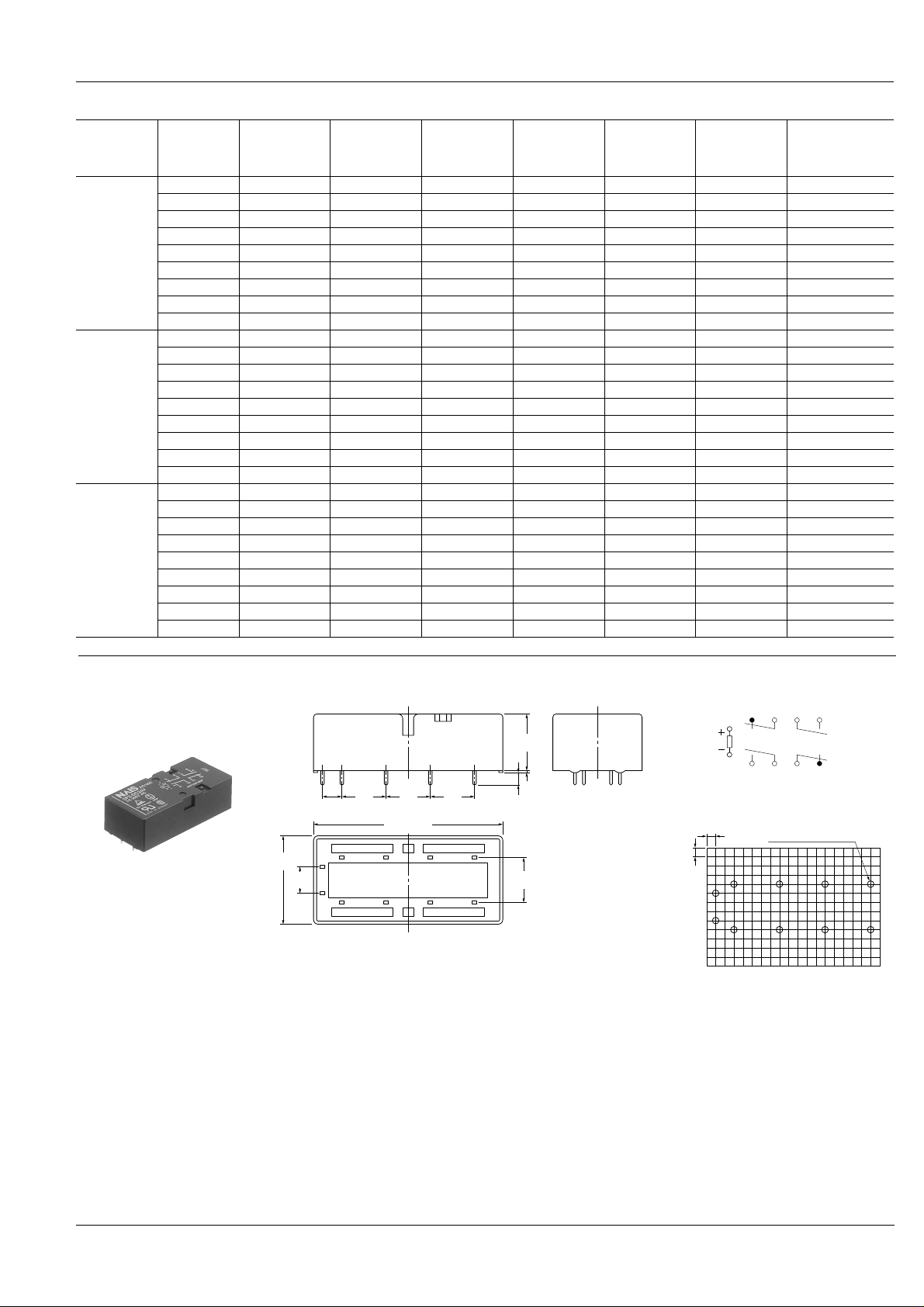
12.7
.500
53.3±0.3
2.098±.012
12.7
.500
12.7
.500
5.08
.200
6587
109
1
2
1211
16±0.3
.630±.012
12.7
.500
3.5±0.3
.138±.012
0.5
.020
25.0
.984
7.62
.300
5678
9 101112
1
2
2.54
.100
2.54
.100
10-1.4 DIA. HOLES
10-.055 DIA. HOLES
General tolerance: ±0.3 ±.012
PC board pattern (Bottom view)
Schematic (Bottom view)
Tolerance: ±0.1 ±.004
2) SF3
3) SF4
mm
inch
3.5±0.3
12.7
12.7
33±0.3
1.299±.012
7.62
.300
5.08
.200
12.7
.500
.500
53.3±0.3
2.098±.012
1413 1615
65
1
2
109
1817 2019
.500
.138±.012
87
1211
General tolerance: ±0.3 ±.012
REFERENCE DATA
1. Operate/release time 2. Coil temperature rise
Coil applied voltage: 120%V
Contact switching current: 6A
16±0.3
.630±.012
0.3
.012
7.62
.300
12.7
.500
7.62
.300
Schematic (Bottom view)
13
14615716
1
5
9171018111912
2
8
20
PC board pattern (Bottom view)
18-1.4 DIA. HOLES
18-.055 DIA. HOLES
2.54
.100
2.54
.100
Tolerance: ±0.1 ±.004
3. Ambient temperature characteristics
Tested sample: SF4-DC12V
Quantity: n = 6
50
40
30
20
Operate/release time, ms
10
0
260
Operate time
80 10090 120110
Release time
Coil applied voltage, %V
Max.
x
Min.
Max.
x
Min.
60
50
40
30
Temperature rise, °C
20
10
0
Inside the coil
Contact
30 50 70
Ambient temperature, °C
 Loading...