

NAIS NR-HD-12V, NR-HL2D-12V, NR-HL2D-42V, NR-HL2D-5V, NR-HLD-24V Datasheet
...
112
NR-RELAYS
LONG LIFE RELAY
CSA
pending
UL
pending
mm inch
10
.394
10
.394
20
.787
FEATURES
• Sealed construction for automatic wave soldering and cleaning
• Latching types available
• High sensitivity — TTL direct drive possible
• High speed — Up to 500 cycle/sec. operations
• Wide switching range and high welding resistance
Gold cobalt (AuCo) contact permits
• Wider switching range from low level up to high current: 10 µ A to 1 A
• Higher sticking resistance to inrush current
• Stable contact resistance from initial stage throughout life
SPECIFICATIONS
Contact
Coil (polarized) (at 25 ° C 77 ° F)
Characteristics (at 25 ° C 77 ° F)
Remarks
* Specifications will vary with foreign standards certification ratings.
*
1
Measurement at same location as "Initial breakdown voltage" section
*
2
Min. 500M Ω at 100 V DC between coils of 2 coil latching type
*
3
Detection current: 10mA, Except for between coils of 2 coil latching type
*
4
Excluding contact bounce time
*
5
Half-wave pulse of sine wave: 6ms; detection time: 10 µ s
*
6
Half-wave pulse of sine wave: 6ms
*
7
Detection time: 10 µ s
*
8
Although NR relays are rated at 10 G/55 cps. vibration resistance, they will withstand up to 60 G/2,000 cps., provided they receive additional support such as
anchoring to the PC board with epoxy resin.
*
9
Refer to 5. Conditions for operation, transport and storage mentioned in
AMBIENT ENVIRONMENT (Page 61)
*
10
T otal temperature (ambient temperature plus temper ature rise in coil) should not
exceed 90 ° C 194 ° F for single side stable, and 105 ° C 221 ° F for latching relays.
See Reference Data for determination of coil voltage versus temperature.
Arrangement 1 Form C
Initial contact resistance, max.
(By voltage drop 6 V DC 1 A)
60 m Ω
Initial contact pressure Approx. 5 g .18 oz
Contact material Gold cobalt
Electrostatic
capacitance
ContactContact
Sealed type 3 pF
Magnetically
sealed type
4 pF
N.O.
contact-coil
Sealed type 4 pF
Magnetically
sealed type
5 pF
N.C.
contact-coil
Sealed type 5 pF
Magnetically
sealed type
6 pF
Nominal switching capacity
1A 20 VDC,
0.3A 110 VAC
Rating
(resistive)
Max. switching power 33 VA, 20 W
Max. switching voltage 110 V AC, 30 V DC
Max. switching current AC 0.3 A, DC 1 A
Min. switching power Approx. 100 mV 10 µ A
Expected
life (min.
operations)
Mechanical (at 500 cps.) 10
9
Electrical
(resistive)
1 A 20 V DC/
0.3 A 110 V AC
10
6
(at 1 cps.)
0.5 A 30 V DC/
0.1 A 110 V AC
3 × 10
6
(at 2 cps.)
0.25 A 30 V DC/
0.25 A 30 V AC
5 × 10
6
(at 5 cps.)
0.2 A 24 V DC/
0.2 A 24 V AC
10
7
(at 25 cps.)
0.1 A 12 V DC/
0.1 A 12 V AC
5 × 10
7
(at 50 cps.)
0.1 A 9 V DC/
0.1 A 9 V AC
10
8
(at 100 cps.)
Minimum operting power
Single side stable 72 to 133 mW
1 coil latching 41 to 45 mW
2 coil latching 72 to 107 mW
Nominal operating power
Single side stable 147 to 300 mW
1 coil latching 74 to 153 mW
2 coil latching 147 to 331 mW
Max. operating speed 500 cps. (mechanical)
Initial insulation resistance*
1
Min. 1000 M Ω at 500 V DC*
2
Initial
breakdown
voltage*
3
Between live parts
and ground
1,000 Vrms
Between open
contact
350 Vrms (500 V DC)
Between contact
and coil
1,000 Vrms
Operate time*
4
(at nominal voltage)
Max. 3 ms (Approx. 1 ms)
Release time (without diode)*
4
(at nominal voltage)
Max. 2 ms (Approx. 0.5 ms)
Contact
bounce
time
Single side stable Approx. 0.5 ms
1-coil /2-coil latching Approx. 0.3 ms
Temperature rise
Max. 35 ° C at 0.5 W operating power
Max. 65 ° C at 1 W operating power
Shock resistance
Functional*
5
Min. 980 m/s
2
{100 G}
Destructive*
6
Min. 980 m/s
2
{100 G}
Vibration
resistance
Functional*
7
98 m/s
2
{10 G}, 10 to 55 Hz
at double amplitude of 1.6 mm*
8
Destructive
117.6 m/s
2
{12 G}, 10 to 55 Hz
at double amplitude of 2 mm
Conditions for operation, transport and
storage*
9
(Not freezing and condensing
at low temperature)
Ambient
temp.
–55 ° C to +65 ° C*
10
–67 ° F to +149 ° F
Humidity 5 to 85% R.H.
Unit weight Approx. 7 g .25 oz

NR
113
TYPICAL APPLICATIONS
Telecommunications equipment, alarm
devices, machine tools, NC machines , automatic warehouse control, conveyors,
air-conditioners, pressing machines, tex-
tile machinery, elevators, control panels,
pin-board programmers, parking meters,
industrial robots, detectors, annunciators,
optical instruments, business machines,
time recorders, cash registers, copiers,
vending machines, medical equipment.
ORDERING INFORMATION
EX.
Types of case
(Notes) 1. Power types and 1 Form A types are available on request.
(Notes) 2. For UL/CSA recognized types, delete “N” at head portion of part No. and add suffix UL/CSA, when ordering. Ex. RSD-12V UL/CSA
(Notes) 3. Standard packing Carton: 50 pcs., Case: 500 pcs.
Operating function
H: Sealed
S: Magnetically sealed
Nil: Single side stable
L: 1 coil latching
L2: 2 coil latching
Coil voltage (DC)
5, 6, 12, 24, 42 V
NR- H L2 D 12V
TYPES AND COIL DATA (at 25 ° C 77 ° F)
Single side stable (NR-SD)
1 coil latching (NR-SLD)
2 coil latching (NR-SL2D)
(Note) Maximum allowable operating power: 1000 mW at 25 ° C 77 ° F.
Nominal coil
voltage, V DC
Pick-up voltage,
V DC (max.)
Drop-out voltage
V DC (min.)
Maximum
allowable voltage,
V DC (40 ° C 104°F)
Coil resistance,
Ω ( ±
10%)
Nominal operating
power, mW
Inductance,
Henrys
5 3.5 0.5 13 170 147 0.050
6 4.7 0.6 14 220 164 0.075
12 9.3 1.2 28 890 162 0.3
24 16 2.4 42 2,000 288 0.66
42 28 4.2 85 8,000 221 2.7
Nominal coil voltage,
V DC
Pick-up voltage,
V DC (max.)
Maximum allowable
voltage,
V DC (40 ° C 104°F)
Coil resistance,
Ω ( ±
10%)
Nominal operating
power, mW
Inductance,
Henrys
5 3.5 18 340 74 0.12
6 4.3 20 450 80 0.16
12 8.0 30 1,500 96 0.66
24 17 75 6,000 96 2.4
42 23 110 12,000 147 3.9
Nominal coil voltage,
V DC
Pick-up voltage,
V DC (max.)
Maximum allowable
voltage,
V DC (40 ° C 104°F)
Coil resistance,
Ω ( ±
10%)
Nominal operating
power, mW
Inductance,
Henrys
Set coil Reset coil
5 3.5 13.0 170 170 147 0.024
6 4.3 14.0 225 225 160 0.04
12 8.0 26.0 650 650 230 0.14
24 17.0 50.0 2,700 2,700 213 0.35
42 23.0 75.0 5,500 5,500 321 0.8
DIMENSIONS
General tolerance: ± 0.5 ± .020 Tolerance: ± 0.2 ± .008
Terminal dimensions (Except soldering)
Soldering: 0.3 .012 max.
2.54
.100
5.1
.201
5.1
.201
5.1
.201
5.1
.201
10
.394
20
.787
3.5
.138
10
.394
3
.118
2.54
.100
2.54
.100
1
23
4
5
67
1.3 DIA.
.051 DIA.
Ground terminal
Terminal No. Thickness Width
1, 7
0.5
.020
0.6
.024
4
0.3
.012
0.7
.028
2, 3, 5, 6,
ground terminal
0.5 DIA.
.020 DIA.
mm inch
NR
114
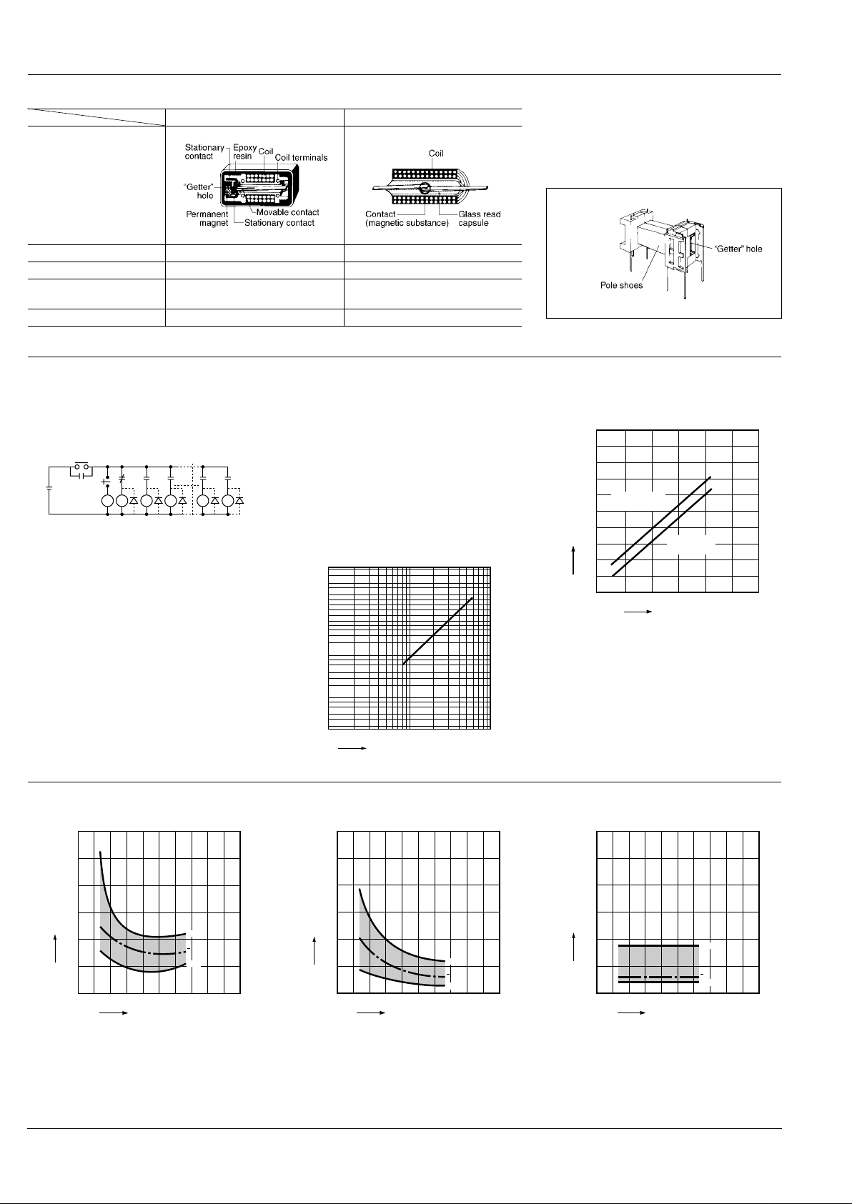
DIFFERENCES BETWEEN NR RELAYS AND REED RELAYS
NR relays Reed relays
Structure
Contact arrangement 1 Form C 1 Form A or 1 Form B
Contact capacity 20 W (high contact pressure) 5 to 15 W
Operating function
Single side stable
Latching
Single side stable
"Getter" hole Yes No
"Getter" holes are formed on both pole
shoes to obtain uniform contact resistance throughout life. Film-forming phenomena on contacts is thus fully
prevented.
REFERENCE DATA
1.-(1) Contact reliability
Test sample: NR-SD-24V 54 pcs.
Circuits: (A) Following figure with diode
(B) Following figure without diode
Item to be checked: Detect with the circuit stopped
Circuits:
(A) Diode provided: The circuit does not stop through-
out 100 million times.
(B) Diode not provided: λ
60
= 2.5 × 10
-8
times
1.-(2) Contact reliability
TEST CONDITION
Sample: NR-SD-24V, 10 pcs.
Contact voltage: 100 mV
Contact current: 10 µ A
Cycle rate: 50 cps.
Detection level: 100 Ω
Testing operation: 3 × 10
7
m = 1.9
σ
= 2.5 × 10
7
µ
= 4.7 × 10
7
95% reliability limit: 1.15 × 10
7
(Mean time between failure)
2. Coil temperature rise
(under saturated condition)
R0
R0
R54 R1 R2 R52 R53
R1 R2 R3 R53 R54
24 V DC
Stop
Start
1051
0.1
0.2
0.5
1.0
2.0
5.0
10.0
30.0
50.0
70.0
95.0
99.0
99.9
F(t)(%)
No. of operations, ×10
7
(WEIBULL)
100
250 500 750 1,000 1,250
90
80
70
60
50
40
30
20
10
Operating power, mW
Coil temperature rise, °C
Magnetically
sealed type
Plastic
sealed type
3.-(1) Operate time including bounce time
(Single side stable)
3.-(2) Operate time including bounce time
(2 coil latching)
4. Release time including bounce time
(Single side stable)
22018014010060
3.0
2.5
2.0
1.5
1.0
0.5
0
Min.
Max.
x
Coil applied voltage, %V
Operate time, ms
22018014010060
3.0
2.5
2.0
1.5
1.0
0.5
0
Min.
Max.
x
Coil applied voltage, %V
Operate time, ms
22018014010060
3.0
2.5
2.0
1.5
1.0
0.5
0
Min.
Max.
x
Coil applied voltage, %V
Release time, ms
 Loading...