

NAIS NL6EBX-DC5V, NL6EBX-DC60V, NL6EBX-DC60V-1, NL6EBX-DC12V-1, NL6EBX-L2-DC12V Datasheet
...
201
NL-RELAYS
6PDT FLATPACK 2AMP
DIL RELAY
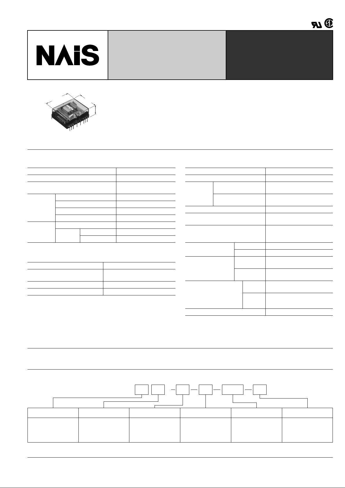
NLE Amber Relays
mm inch
10.9
.429
25.4
1.000
32.4
1.276
FEATURES
• Space saving dimensions — 25.4 mm × 32.4 mm × 10.9 mm
1.000 inch × 1.276 inch × 0.429 inch
• Latching types available
• Low operating power — 400 mW (single side stable)
Transistor compatible
• High breakdown voltage for transient protection — 1,000 Vrms between open
contacts, contact sets, and 1,500 V FCC surge between open contacts
• Soldering flux inflow completely prevented
SPECIFICATIONS
Contacts
**
1
MBB contact types also available: 2 MBB, 4 MBB & 6 MBB
**
2
Gold capped silver-palladium contact also available
Coil (polarized) (at 25 ° C 77 ° F)
Remarks
* Specifications will vary with foreign standards certification ratings.
*
1
Measurement at same location as "Initial breakdown voltage" section
*
2
Detection current: 10 mA
*
3
Excluding contact bounce time
*
4
Half-wave pulse of sine wave: 11ms; detection time: 10 µ s
*
5
Half-wave pulse of sine wave: 6ms
*
6
Detection time: 10 µ s
*
7
Refer to 5. Conditions for operation, transport and storage mentioned in
AMBIENT ENVIRONMENT (Page 61).
Characteristics
Arrangement**
1
6 Form C
Contact material gold-clad silver**
2
Initial contact resistance, max.
(By voltage drop 6 V DC 1 A)
100 m Ω
Rating
(resistive)
Nominal switching capacity 2 A 30 V DC
Max. switching power 60 VA, 60 W
Max. switching voltage 125 V AC, 30 V DC
Max. switching current 2 A
Expected
life (min.
operations)
Mechanical 5 × 10
7
Electrical
(resistive)
2 A 30 V DC 5 × 10
5
0.6 A 100 V DC 10
6
Minimum operating power Approx. 460 mW
Nominal operating power
up to 60 V DC: Approx. 720 mW
110 V DC: Approx. 900 mW
Minimum set and reset power Approx. 1,000 mW
Nominal set and reset power Approx. 1,600 mW
Maximum operating speed 50 cps
Initial insulation resistance*
1
Min. 100 M Ω at 500 V DC
Breakdown
voltage*
2
Between open contacts,
contact sets
1,000 Vrms
Between contacts and
coil
2,000 Vrms
Operate time*
3
(at nominal voltage) Max. 15 ms (Approx. 10 ms)
Release time (without diode)*
3
(at nominal voltage)
Max. 10 ms (Approx. 5 ms)
Temperature rise
Max. 65 ° C
with nominal coil voltage
and at switching current 2 A
Shock resistance
Functional*
4
Min. 147 m/s
2
{15 G}
Destructive*
5
Min. 980 m/s
2
{100 G}
Vibration resistance
Functional*
6
58.8 m/s
2
{6 G}, 10 to 55 Hz
at double amplitude of 1 mm
Destructive
117.6 m/ s
2
{12 G}, 10 to 55 Hz
at double amplitude of 2 mm
Conditions for operation,
transport and storage*
7
(Not freezing and condensing at low temperature)
Ambient
temp.
–40 ° C to +55 ° C
–40 ° F to +131 ° F
Humidity 5 to 85% R.H.
Unit weight Approx. 17 g.60 oz
TYPICAL APPLICATIONS
Telecommunications, security equipment, detection systems.
ORDERING INFORMATION
Ex.
Contact arrangement Classification of type MBB function Operating function Coil voltage Contact material
6: 6 Form C EB: Amber sealed type Nil: 6 Form C Nil: Single side
Nil: stable
L2: 2 coil latching
Nil: Gold-clad silver
1: Gold-cap over
1: silver palladium
DC: 5, 6, 12, 24,
48, 60, 110 V
NL 6 EB X 6M L2 DC48V 1
(Notes) 1. For UL/CSA or VDE recognized types, add suffix UL/CSA or VDE.
(Notes) 2. Standard packing Carton: 20 pcs. Case: 200 pcs.
NL
202
TYPES AND COIL DATA (at 20 ° C 68 ° F)
Single side stable 2 coil latching
* See NOTE 2
** Two coil latching series are for intermittent operation only.
Power should be applied to coil continuously for no more than two minutes.
Part No.
Coil voltage, V DC
Coil
resistance,
Ω ( ±
10%)
Nominal
operating
power,
mW
Pick-up
(max.)
Drop-out
(min.)
Maximum
allowable
NL6EBX-DC5V 4.0 0.5 6.0 34.7
720
NL6EBX-DC6V 4.8 0.6 7.2 50
NL6EBX-DC12V 9.6 1.2 14.4 200
NL6EBX-DC24V 19.2 2.4 28.8 800
NL6EBX-DC48V 38.4 4.8 57.6 3,200
NL6EBX-DC60V 48 6.0 72 5,000
NL6EBX-DC110V 88 11.0 132 13,467 898
Part No.
Coil voltage,* V DC
Coil
resistance,
Ω ( ±
10%)
Nominal
operating
power,
mW
Set
(max.)
Reset
(max.)
Maximum
allowable
NL6EBX-L2-DC5V
4.0 4.0 5.5 15.6
1,600**
NL6EBX-L2-DC6V
4.8 4.8 6.6 22.5
NL6EBX-L2-DC12V
9.6 9.6 13.2 90
NL6EBX-L2-DC24V
19.2 19.2 26.4 360
NL6EBX-L2-DC48V
38.4 38.4 52.8 1,440
NL6EBX-L2-DC60V
48
48
66 2,250
NL6EBX-L2-DC110V
88
88
121 7,563
DIMENSIONS
Single side stable
32.4 1.276
2.54
.100
5.08
.200
2.54
.100
2.54
.100
5.08
.200
2.54
.100
10.9
.429
3.5
.138
27.94
1.100
25.4
1.000
Schematic (Top view)
22 21 20 19 18 17
12356
16 15 14 13 12 11
8910
PC board pattern
(Bottom view)
1112 13 1415 16 1718 19 2021 22
1098 6 5 321
2.54×11
.100×11
2.54
.100
2.54
.100
20-1.2 DIA HOLES
20-.047 DIA HOLES
2 coil latching
2.54
.100
5.08
.200
2.54
.100
32.4 1.276
2.54
.100
5.08
.200
2.54
.100
10.9
.429
3.5
.138
27.94
1.100
25.4
1.000
Schematic (Top view)
22 21 20 19 18 17
1235647
16 15 14 13 12 11
8910
PC board pattern
(Bottom view)
1112 13 1415 16 1718 19 2021 22
1098657 4321
2.54×11
.100×11
2.54
.100
2.54
.100
22-1.2 DIA HOLES
22-.047 DIA HOLES
General tolerance: ± 0.3 ± .012
mm inch
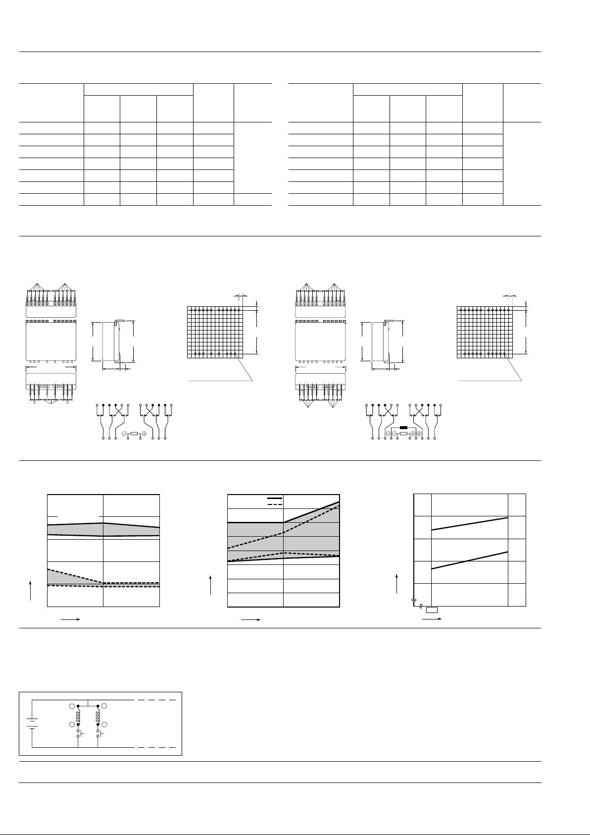
REFERENCE DATA
1. Electrical life (2 A 30 V DC resistive load) 2. Coil temperature rise
Pick-up/drop-out voltage, V
No. of operations, ×10
4
Drop-out voltage
Pick-up voltage
Max.
Max.
Min.
Min.
50 100
0
5
10
15
20
25
Contact resistance, mΩ
No. of operations, ×10
4
Max.
Max.
Min.
N.C. contact
N.O. contact
50 100
0
10
20
30
40
50
60
70
Temperature rise, °C
Coil applied voltage,%V
110
100
0
30
40
50
60
70
2 A carrying
No load
NOTES
On two coil latching relays
1. To maintain insulation between coils,
terminals 6 and 7 should be connected to
provide common return.
2. Two coil latching relays are for intermittent operation only. Power should be applied to coils for no more than two
minutes; continuous operation may burn
out the coils.
3. Position of MBB contacts
2M (2 Form D 4 Form C):
1-21-22, 10-11-12
4M (4 Form D 2 Form C):
1-21-22, 2-20-18, 9-13-15, 10-11-12
Latch coil
Latch switch
6
5
Reset coil
Reset switch
7
4
For Cautions for Use, see Relay Technical Information (Page 48 to 76).
9/1/2000 All Rights Reserved, © Copyright Matsushita Electric Works, Ltd.
Go To Online Catalog
 Loading...