

NAIS NF2EB-12V, NF2EB-5V, NF4EB-24V-1, NF4EB-5V-1, NF4EB-6V-1 Datasheet
...
198
NF-RELAYS
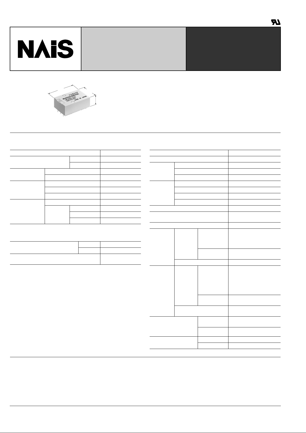
FLATPACK RELAY
CSA
pending
mm inch
10.8
.425
20.0
.787
30.2
1.189
FEATURES
1. Flatpack
2. Long seller
SPECIFICATIONS
Contacts
1].
MBB types available: 2MBB & 4MBB
(See next page for contact positions.)
Coil
Remarks
* Specifications will vary with foreign standards certification ratings.
*
1
Measurement at same location as "Initial breakdown voltage" section
*
2
Detection current: 10 mA
*
3
Excluding contact bounce time
*
4
Half-wave pulse of sine wave: 11ms; detection time: 10 µ s
*
5
Half-wave pulse of sine wave: 6ms
*
6
Detection time: 10 µ s
*
7
Refer to 5. Conditions for operation, transport and storage mentioned in
AMBIENT ENVIRONMENT (Page 61).
Characteristics (at 25 ° C 77°F, 50% R.H. seal level)
Arrangement
1]
2 Form C, 4 Form C
Initial contact resistance
(By voltage drop 6 V DC 1 A)
Max. 50 m Ω
Typical 25 m Ω
Contact material
Movable contact Gold-clad silver
Stationary contact Gold-clad silver
Rating,
(resistive load)
Max. switching power 60 W 100 VA
Max. switching voltage 220 V AC, DC
Max. switching current 2 A
Expected life
(min. operations)
Mechanical 10
8
Electrical
(Resistive)
2 A 30 V DC 2 × 10
5
1 A 30 V DC 10
6
0.5 A 30 V DC 10
7
Nominal operating power, at 25 ° C
2C Approx. 300 mW
4C Approx. 480 mW
Max. operating power for continuous duty
Approx. 1 W
at 40 ° C 104 ° F
Max. operating speed 50 cps
Initial insulation resistance*
1
1,000 M Ω at 500 V DC
Electrostatic
capacitance
Contact/Contact Approx. 4 pF
Contact/Coil Approx. 7 pF
Contact/Ground Approx. 6 pF
Initial
breakdown
voltage*
2
Between open contacts 750 Vrms
Between contact sets 1,000 Vrms
Between live parts and ground 1,000 Vrms
Between contacts and coil 1,000 Vrms
Operate time*
3
(at nominal voltage) Max. 15 ms (Approx. 10 ms)
Release time (without diode)*
3
(at nominal voltage)
Max. 10 ms (Approx. 3 ms)
Contact bounce Approx. 1.5 ms
Shock
resistance
Functional*
4
In de-energized
condition
Min. 29.4 m/s
2
{3 G}
(In contact direction)
Min. 98 m/s
2
{10 G}
(perpendicular to contact)
In energized
condition
Min. 196 m/s
2
{20 G}
Destructive*
5
Min. 980 m/s
2
{100 G}
Vibration
resistance
Functional*
6
In de-energized
condition
29.4 m/s
2
{3 G}, 10 to 55 Hz
at double amplitude of 0.5 mm
(in contact direction)
98 m/s
2
{10 G}10 to 55 Hz
at double amplitude of 1.6 mm
(perpendicular to contact)
In energized
condition
117.6 m/s
2
{12 G}10 to 55 Hz
at double amplitude of 2 mm
Destructive
196 m/s
2
{20 G}, 10 to 55 Hz
at double amplitude of 3.3 mm
Conditions for operation,
transport and storage*
7
(Not freezing and condensing at low temperature)
Ambient temp.
–40
°
C to + 65 ° C
–40
°
F to +149 ° F
Humidity 5 to 85%R.H.
Unit weight
2C Approx. 14 g .49 oz
4C Approx. 15.5 g .55 oz
TYPICAL APPLICATIONS
NF relays are widely acceptable in applications where small size and high sensitivity are required.
Such applications include: Electronic
equipment, Household applications,
Alarm systems, Office machines, Communication equipment, Measuring equipment, Remote control systems, General
control circuits, Machine tools, Industrial
machinery, etc.
NF
199
ORDERING INFORMATION
Ex. NF
Contact arrangement Type classification MBB function Contact metarialCoil voltage (DC)
2: 2 Form C
4: 4 Form C
EB: Standard Nil: Form C type
2M: 2MBB (2 Form D)
4M: 4MBB (4 Form D)
5, 6, 12,
24, 48 V
Nil: Gold-clad silver
1: Gold-cap over silver palladium
4 EB 4M 48V 1
(Notes) 1. For VDE recognized types, add suffix VDE.
(Notes) 2. For UL/CSA recognized type, add suffix-A, as NF2EB-12V-A whose ground terminal is cut off.
(Notes) 3. Standard packing Carton: 20 pcs.; Case: 200 pcs.
*Less than 1,000 Ω :
*More than 1,000 Ω :
±
10%
±
15%
Part No.
Nominal voltage,
V DC
Pick-up voltage,
V DC (max.)
Drop-out
voltage,
V DC (min.)
Max. allowable
voltage,
V DC (at 40 ° C)
Coil resistance,*
Ω
Nominal
operating power ,
mW
Inductance, H
Armarure
Open Close
NF2EB-5V 5 4.0 0.5 8.7 90 278 0.071 0.071
NF2EB-6V 6 4.8 0.6 10.5 137 260 0.093 0.094
NF2EB-12V 12 9.6 1.2 21 500 290 0.338 0.344
NF2EB-24V 24 19.2 2.4 42 2,000 290 1.29 1.31
NF2EB-48V 48 38.4 4.8 84 7,000 330 4.12 4.18
NF4EB-5V 5 4.0 0.5 7 53 472 0.029 0.029
NF4EB-6V 6 4.8 0.6 8.5 90 400 0.070 0.071
NF4EB-12V 12 9.6 1.2 17.0 330 440 0.22 0.23
NF4EB-24V 24 19.2 2.4 34 1,200 480 0.77 0.79
NF4EB-48V 48 38.4 4.8 68 4,200 550 2.22 2.25
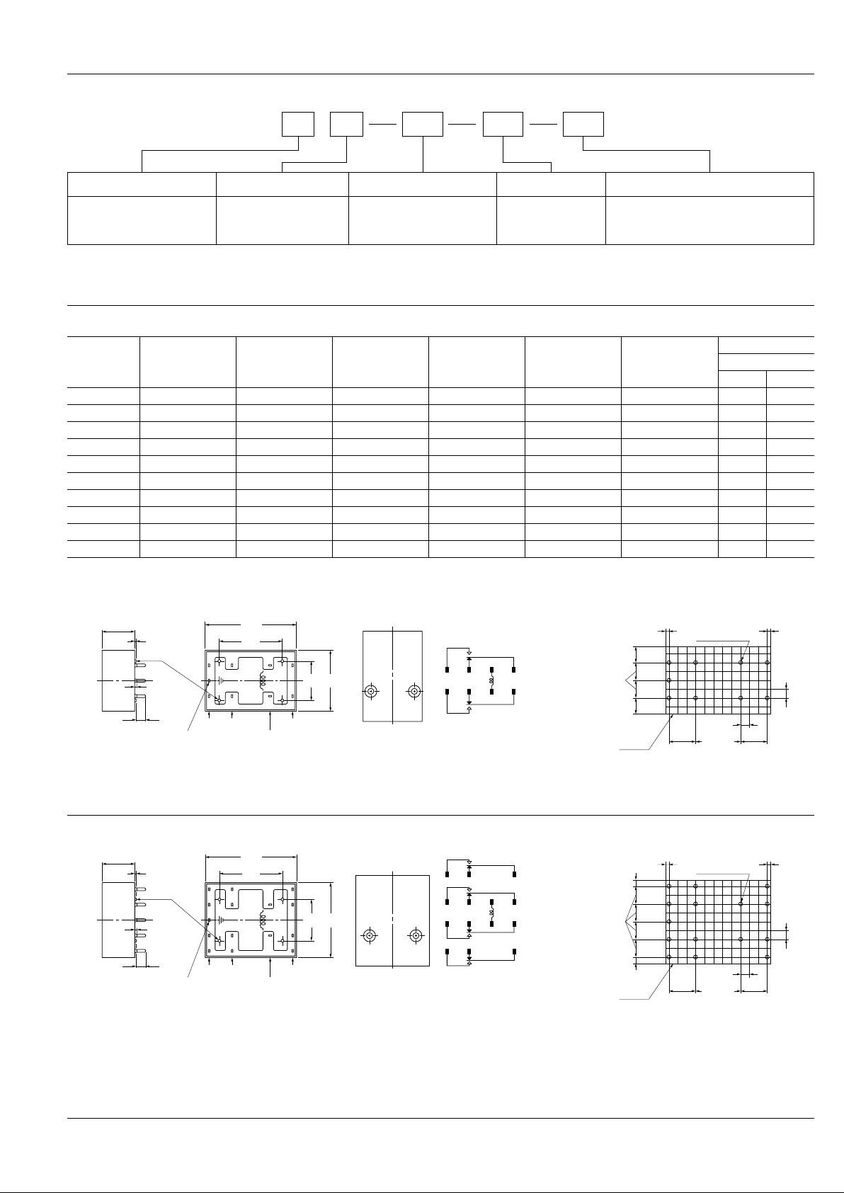
DIMENSIONS
2 Form C
10.8±0.3
.425±.012
0.3
.012
3.3
.130
Resin rise
max. 0.5
max. .020
4-0.8 dia.
.031 dia.
Stand-off
20.6
.811
30.2
1.189
20
.787
13
.512
N.O.
Ground terminal
N.C.
Coil terminal
Common terminal
Terminal dimensions (except soldering)
Width: 0.8 .031
Thickness: 0.3 .012
MBB contact position
NF2-2M: terminal 6-7-8, 3-4-5
58
47
12
36
Schematic
PC board pattern (Copper-side view)
(2.54)
(.100)
7.6±0.2
.3±.008
7.6±0.2
.3±.008
12.7±0.2
.5±.008
(2.54)
(.100)
4.9
.193
5.1±0.2
.2±.008
4.9
.193
1.13
.044
1.13
.044
1.3
.051 DIA.
+0
–0.3
+0
–.012
Relay
outline
mm inch
4 Form C
General tolerance: ± 0.5 ± .020
(Except for the cover height)
811
710
12
6
5
4
39
14
13
12
10.8±0.3
.425±.012
0.3
.012
3.3
.130
Resin rise
max. 0.5
max. .020
4-0.8 dia.
.031 dia.
Stand-off
20.6
.811
30.2
1.189
24.6
.969
13.6
.535
N.O.
Ground terminal
N.C.
Coil terminal
Common terminal
Terminal dimensions (except soldering)
Width: 0.8 .031
Thickness: 0.3 .012
Schematic
MBB contact position
NF4-2M: terminals 6-7-8, 9-10-11
NF4-2M: terminals 6-7-8, 3-4-5, 12-13-14, 9-10-11
PC board pattern (Copper-side view)
(2.54)
(.100)
7.6±0.2
.3±.008
7.6±0.2
.3±.008
12.7±0.2
.5±.008
(2.54)
(.100)
2.1
.083
5.1±0.2
.2±.008
2.1
.083
1.13
.044
1.13
.044
1.3
.051 DIA.
Relay
outline
+0
–0.3
+0
–.012
TYPES AND COIL DATA (at 25 ° C 77 ° F)
 Loading...