

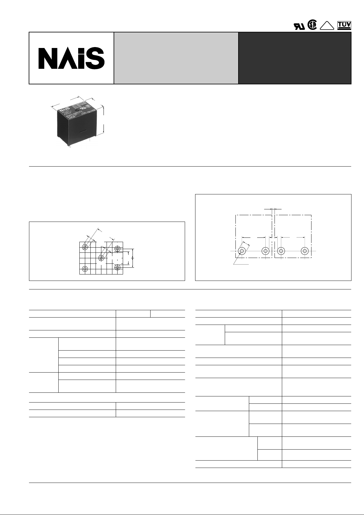
NAIS JE1XN-DC9V-H, JE1XN-DC6V-H, JE1XN-DC5V-H, JE1XN-DC24V-H, JE1XN-DC12V-H Datasheet
...
295
JE-X
RELAYS
COMPACT ECONOMICAL
POWER RELAYS
VDE
mm inch
18.7
.736
14
.551
22
.866
FEATURES
• Compact size - Height Max. 18.7 mm .736 inch
lower than JY relay (22.5 mm) (.886 inch)
• High contact capacity — 5A 125 V AC
• Safety-oriented between coil and contact terminals
• All plastic materials: UL flame retardance 94V-0
• VDE, TÜV also approved
TERMINAL LAYOUT
Distance of 9.16 mm .360 inch between common and coil terminals and 8.9 mm .350 inch between contacts give room to the
land diameter width when the relay is mounted on PC board, and
allow design of patterns with insulation distances of 6 mm .236
inch between common and coil and 5.9 mm .232 inch between
contacts.
• 3 mm .118 inch or more insulation distance for close
mounting can be kept easily with JE-X relays.
In case of 3 mm
.118 inch land
diameter
5.9
.233
3 dia.
.118 dia.
3 dia.
.118 dia.
4.45
.175
9.16
.361
Coil
Coil
COM
N.O.
N.C.
4.45
.175
6.16
.243
1.3 dia.
.051 dia.
3 dia.
.118 dia.
8.9
.350
0.9
.035
N.O.N.C.
R1
8.9
.350
3
.118
N.O.N.C.
R2
SPECIFICATIONS
Contact
Coil
Remarks
* Specifications will vary with foreign standards certification ratings.
*
1
Measurement at same location as "Initial breakdown voltage" section
*
2
Detection current: 10 mA
*
3
Wave is standard shock voltage of ± 1.2 × 50 µ s according to JEC-212-1981
*
4
Excluding contact bounce time
*
5
Half-wave pulse of sine wave: 6ms; detection time: 10 µ s
*
6
Half-wave pulse of sine wave: 6ms
*
7
Detection time: 10 µ s
*
8
Refer to 5. Conditions for operation, transpor t and storage mentioned in
AMBIENT ENVIRONMENT (Page 61).
Characteristics
Arrangement 1 Form A 1 Form C
Initial contact resistance, max.
(By voltage drop 6 V DC 1A)
100 m Ω
Contact material Silver alloy
Rating
(resistive
load)
Nominal switching
capacity
5 A 30 V DC, 5 A 125 V AC,
3A 250 V AC
Max. switching power 750 VA, 150 W
Max. switching voltage 250 V AC, 30 V DC
Max. switching current 5 A
Expected
life (min.
operations)
Mechanical (at 180 cpm) 5 × 10
6
Electrical (at 20 cpm)
(at rated load)
10
5
Minimum operating power 196 mW
Nominal operating power 400 mW
Max. operating speed 20 cpm (at 70 ° C)
Initial insulation resistance*
1
Min. 100 M Ω (at 500 V DC)
Initial
breakdown
voltage*
2
Between open contacts 750 Vrms
Between contacts and
coil
1,500 Vrms
Surge voltage between coil
and contact*
3
Min. 5,000 V
Operate time*
4
(at nominal voltage) Approx. 10 ms
Release time (without diode)*
4
(at nominal voltage)
Approx. 2 ms
Temperature rise (at 70 ° C)
Max. 45 ° C with nominal coil
voltage and at nominal
switching capacity
Shock resistance
Functional*
5
Min. 98 m/s
2
{10 G}
Destructive*
6
Min. 980 m/s
2
{100 G}
Vibration resistance
Functional*
7
98 m/s
2
{10 G}, 10 to 55 Hz
at double amplitude of 1.6 mm
Destructive
117.6 m/s
2
{12 G}, 10 to 55 Hz
at double amplitude of 2.0 mm
Conditions for operation,
transport and storage*
8
(Not freezing and condensing at low temperature)
Ambient
temp.
–40 ° C to +70 ° C
–40 ° F to +158 ° F
Humidity 5 to 85% R.H.
Unit weight Approx. 9.2g .32 oz
mm inch mm inch

JE-X
296
TYPICAL
APPLICATIONS
• Home appliances
Oven, range, dryer, heater,
Air conditioner etc.
• Automotive
• Garage door opener
• Personal computer
• Programmable controller
ORDERING INFORMATION
1NXHDC12VEx. JE
Contact arrangement
(Note) Standard packing: Carton 100 pcs. Case 500 pcs.
UL/CSA, VDE approved type is standard.
Pick-up voltage Coil voltage
Protective
construction
1a: 1 Form A
1:1 Form C
N:70% of nominal voltage DC 5, 6, 9,
12, 24, 48 V
H: Flux-resistant type
TYPES
Contact arrangement Coil voltage
Pick-up 70% V type
Flux-resistant type
1 Form A
5 V DC JE1aXN-DC5V-H
6 V DC JE1aXN-DC6V-H
9 V DC JE1aXN-DC9V-H
12 V DC JE1aXN-DC12V-H
24 V DC JE1aXN-DC24V-H
48 V DC JE1aXN-DC48V-H
1 Form C
5 V DC JE1XN-DC5V-H
6 V DC JE1XN-DC6V-H
9 V DC JE1XN-DC9V-H
12 V DC JE1XN-DC12V-H
24 V DC JE1XN-DC24V-H
48 V DC JE1XN-DC48V-H
COIL DATA (at 20 ° C 68 ° F)
Nominal voltage,
V DC
Pick-up voltage,
V DC (max.)
Drop-out voltage,
V DC (min.)
Nominal operating
currrent,
mA ( ± 10%)
Coil resistance,
Ω ( ±
10%)
Nominal operating
power,
mW
Maximum
allowable voltage,
V DC (at 70 ° C)
5 3.5 0.5 80 62.5 400 6.5
6 4.2 0.6 67 90 400 7.8
9 6.3 0.9 44 202 400 11.7
12 8.4 1.2 33 360 400 15.6
24 16.8 2.4 17 1,440 400 31.2
48 33.6 4.8 8.3 5,760 400 62.4
DIMENSIONS
14
.551
22
.866
0.5
.020
0.8
.031
4.45
.175
4.45
.175
0.4
.016
N.C.
N.O.
COM
3
4
5
2
1
1.1
.043
1.2
.047
0.8
.031
3.9
.154
0.3
.012
3.9
.154
Max.
18.2
.717
7.62
.300
10.16
.400
7.62
.300
Dimension
: General tolerance
Max. 1mm .039 inch:
±
0.2 ± .008
1 to 5mm .039 to .197 inch: ± 0.3 ± .012
Min. 5mm .197 inch:
±
0.4 ± .016
PC board pattern (Copper-side view)
Tolerance: ± 0.1 ± .004
Schematic (BOTTOM VIEW)
5-1.3 dia.
5-.051 dia.
10.16
.400
7.62
.300
7.62
.300
4.45
.175
4.45
.175
COM
N.O.
N.C.
3
4
5
1
2
Note: The above shows 1 Form C type, and No . 5
terminal is eliminated on the 1 Form A type.
mm inch
 Loading...