

NAIS HX2-24V, HX2-3V, HX2-4.5V, HX2-5V, HX2-6V Datasheet
...
❇
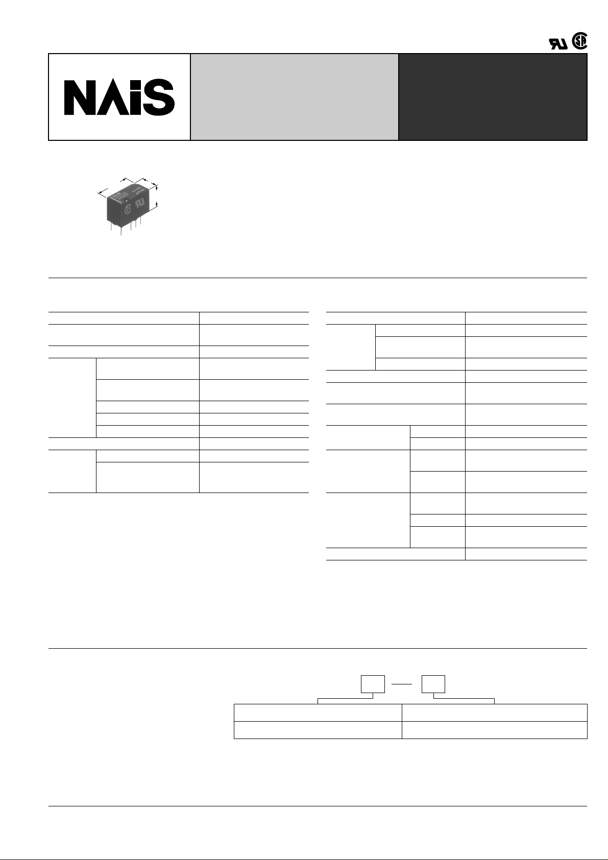
Compact & Slim 2 Form C
Non-polarized Relay
HX-RELAYS
FEATURES
15.0
.591
7.4
.291
9.4
.370
• Compact size of (W) 7.4 × (L) 15.0 × (H)
9.4 mm (W) .291 × (L) .591 × (H) .370
inch.
• Surge withstand voltage of 1,500 V
(between contact and coil)
Conforms to FCC Part 68.
mm inch
• High-density mounting is possible
• High reliability
The use of a gold-clad bifurcated structure for the movable contacts, and a low
gas material for the forming materials and
coil wiring ensures high contact reliability.
SPECIFICATIONS
Contact
Arrangement 2 Form C
Initial contact resistance
(By voltage drop 6 V DC 1 A)
Contact material Gold-clad silver alloy
Nominal switching
capacity (resistive load)
Max. switching power
Rating
(resistive load)
Max. switching voltage 110 V DC, 125 V AC
Max. switching current 1 A
Min. switching capability ❇ 1
Nominal operating power 320 mW
Expected
life (min.
operations)
Mechanical (at 180 cpm) 10
Electrical (at 20 cpm)
Note:
1This value can change due to the switching frequency, en vironmental conditions,
and desired reliability level, therefore it is recommended to chec k this with the actual load.
Remarks
* Specifications will vary with foreign standards certification ratings.
1
*
Measurement at same location as "Initial breakdown voltage" section.
2
By resistive method, nominal voltage applied to the coil; contact carrying current:
*
1A.
3
Nominal voltage applied to the coil, excluding contact bounce time.
*
4
*
Half- wave pulse of sine wave: 11ms, detection time: 10 µ s
5
Half- wave pulse of sine wave: 6ms
*
6
*
Detection time: 10 µ s
7
*
Refer to 5. Conditions for operation, transport and storage mentioned in
AMBIENT ENVIRONMENT (Page 61)
Max. 100 m Ω
1 A 30 V DC, 0.3 A 125 V AC
30 W (DC), 37.5 VA (AC)
1 mA 1 V DC
7
5
10
(1 A 30 V DC,
0.3 A 125 V AC resistive)
Characteristics
Initial insulation*
Initial
breakdown
voltage
Temperature rise*
Operate time*
(at 20 ° C 68 ° F)
Release time(without diode)*
(at 20 ° C 68 ° F)
Shock resistance
Vibration resistance
Conditions for
opetation, transport
and storage*
Unit weight Approx. 2g .07 oz
1
resistance Min. 1,000 M Ω (at 500 V DC)
Between contacts 750 V rms for 1 min.
Between contact and
coil
1,000 V rms for 1 min.
Between contacts sets 1,000 V rms for 1 min.
2
3
3
Functional*
Destructive*
Functional*
Destructive
4
5
6
at double amplitude of 1.0 mm
at double amplitude of 1.5 mm
Ambient
temperature
7
Humidity 5 to 85% R.H.
Atmospheric
pressure
Max. 60 ° C
Max. 6 ms (Approx. 4 ms)
Max. 5 ms (Approx. 3 ms)
Min. 100 m/s
Min. 1,000 m/s
2
{10G}
2
{100G}
10 to 55 Hz
10 to 55 Hz
–40 to +70 ° C
–40 to +158 ° F
86 to 106 kPa
TYPICAL
APPLICATIONS
• Telephone exchange, transmission
equipment
• Communications devices
• Measurement devices
• Home appliances, and audio/visual
equipment
• Office equipment
ORDERING INFORMATION
Ex. HX 2 3V
Contact arrangement Coil voltage(DC)
2: 2 Form C 1.5, 3, 4.5, 5, 6, 9, 12, 24 V
Note: 2,500V Surge (Bellcore) type is also available.
Please consult us for details.
183
HX
TYPES AND COIL DATA
Part No.
Contact
arrangement
Coil rating,
V DC
1.5 HX2-1.5V 1.13 0.15 214 7.0 320 1.65
3 HX2-3V 2.25 0.3 107 28.1 320 3.3
4.5 HX2-4.5V 3.38 0.45 71.1 63.3 320 4.95
2 Form C
5 HX2-5V 3.75 0.5 64.0 78.1 320 5.5
6 HX2-6V 4.5 0.6 53.6 112 320 6.6
9 HX2-9V 6.75 0.9 35.6 253 320 9.9
12 HX2-12V 9 1.2 26.7 450 320 13.2
24 HX2-24V 18 2.4 13.3 1,800 320 26.4
Standard packing: Tube; 40 pcs.; Case : 1,000 pcs.
Standard
PC board
terminal
arrangement
Pick-up
voltage,
V DC (max.)
(at 20 ° C 68 ° F)
V DC (min.)
(at 20 ° C 68 ° F)
Drop-out
voltage,
(at 20 ° C 68 ° F)
Normal
operating
current,
mA ( ± 10%)
Resistance,
ohm ( ± 10%)
(at 20 ° C 68 ° F)
Coil
Nominal
operating
power,
mW
Max. allowable
voltage,
V DC
(at 70 ° C 158 ° F)
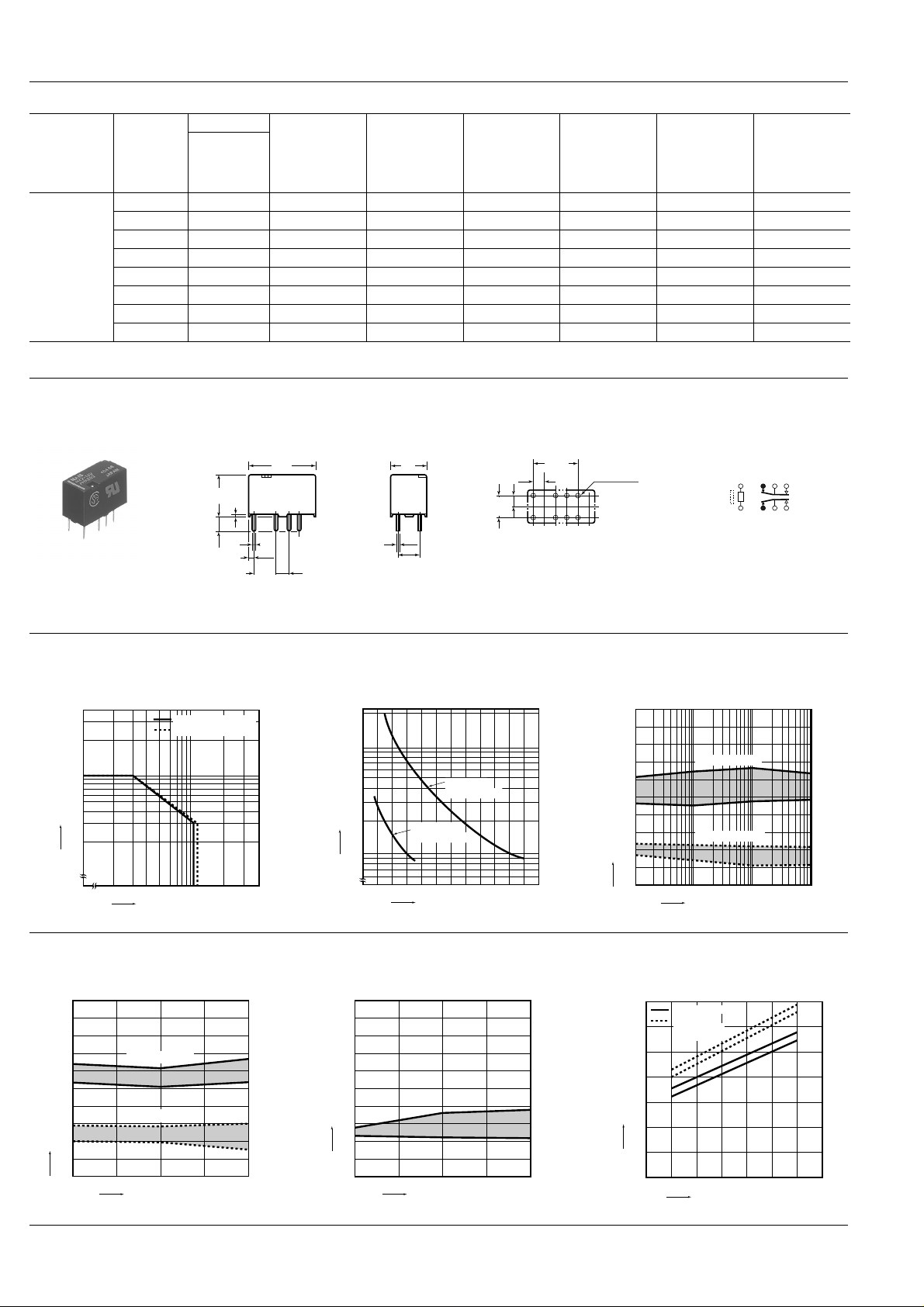
DIMENSIONS
1. Standard PC board terminal type
9.4
0.45
.370
.018
3.5
.138
1.15
.138
General tolerance: ± 0.3 ± .012
0.5
.020
5.08
.200
15.00
.591
2.54
.100
0.25
.010
7.4
.291
5.08
.200
PC board pattern (Bottom view)
10.16
5.08
.200
2.54
.100
.400
2.54
.100
8-1 dia
8-.039 dia
T olerance: ± 0.1 ± .004
REFERENCE DATA
1. Maximum switching capacity 2. Life curve 3. Mechanical life
3.0
2.0
1.0
0.5
0.4
Switching current, A
0.3
0.2
20 30 50 100 200 300
Switching voltage, V
DC load (cos ϕ = 1)
AC load (cos ϕ = 1)
200
4
100
50
30
20
No. of operations, ×10
10
0.2 0.4 0.6 0.8 1.0 1.2
30 V DC
resistive load
125 V AC
resistive load
Switching current, A
Tested sample: HX2-12 V, 10 pcs.
100
90
80
70
60
50
40
30
20
Ratio against the rated voltage, %V
10
0
mm inch
Schematic (Bottom view)
112310495
8
Pick-up voltage
Drop-out voltage
100 500 1,000
No. of operations, ×10
4
Max.
Min.
Max.
Min.
4. Electrical life (1 A 30 V DC resistive load)
Tested sample: HX2-12 V, 6 pcs.
Operating frequency: 20 cpm
Change of pick-up and drop-out voltage Change of contact resistance
100
90
80
70
60
50
40
30
20
Ratio against the rated voltage, %V
10
0
Pick-up voltage
Drop-out voltage
510
No. of operations, ×10
Max.
Min.
Max.
Min.
4
Contact resistance, mΩ
100
90
80
70
60
50
40
30
20
10
0
510
No. of operations, ×10
184
5. Coil temperature rise
Tested sample: HX2-12 V
Measured portion: Inside the coil
Ambient temperature: 25 ° C 77 ° F, 70 ° C 158 ° F
70
70°C 158°F
Room
temperature
60
(25°C 77°F)
50
40
Max.
Min.
4
30
Temperature rise, °C
20
10
0
100 110 120 130 140 150
Coil applied voltage, %V
1 A
0 A
1 A
0 A
 Loading...